Note: Descriptions are shown in the official language in which they were submitted.
WO 93/01866 PC.'T/AU92/0008~
~ j: ~:
~ ~.~ 'a () r~
T~1ET SUPPORT STRUCTURE
This invention relates to a net support structure
and in particular to a net support structure for supporting
a tennis net, volleyball net a practice or protection net
and the like.
Conventional net supports for tennis nets,
volleyball nets or the like generally comprise posts which
are either permanently fixed to the ground or located in
sockets in the ground. Both of the conventional structures
require the net to be located in a predetermined position by
virtue of the fixed post or the fixed sockets into which the
posts are inserted and do not allow the net to be easily set
.up in other environments for use on any suitable playing
CA 02113466 2003-07-04
WO 93/01866 PCTlAU92/0008 i
2 _.
surface.
The object. of this invention is to provide a net
support structure which is easily fi:ransportable and which
can be set up on any suitable playing area.
The invention may be said to reside in a net
support structure compri~s~.ng;
a pair of tubular upright members;
a tubular cross frame member;
at least two joining members for adjacently joining
respective ends of the upright members to respective ends of
the cross frame member;
a single elastic tensioning cord extending interiorly
through the upright members, joining members and cross frame
member;
wherein when the tensioning cord is in tension, the
upright members, the joining members and the cross frame
member are biased .by the tensioning cord to be compressed
against each other to form an exacted net support structure,
and when disconnected from one another, the upright members
and the cross frame member remain joined by the tensioning
cord in a slack condition to maintain the upright members
and cross frame member together and allow the net support
structure to be collapsed and stared; and
wherein the net support structure supports a net over
which a ball is to be hit, and the tensioning cord has free
ends projecting from the upright members, and further
including a net for connection to the free ends of the
tensioning cord for placing the tensioning cord in tension
and also tensioning the net in the net support structure.
Since the net support comprises upright members
and the cross member which are joined by a joining member
they can be easily disconnected for transportation and
storage and can be set up anywhere and will be self
supporting by virtue of the tension applied by the tension
' CA 02113466 2003-07-04
WU 93!01866 PCT/AU92l00087
3 ._
means and also with the tension means. Thus, the net can be
set up on any suitable playing area without the need of
fixed posts or sockets in the ground for receiving posts.
Preferably the 3oining members comprises a joinino
elbow having first and second sockets for receiving ends o~
the upright members and the cross member.
Preferably the joinxr~g members includes an
additional pair of sockets cojoi.nec in a plane transverse to
a plane containing the first and second sockets, for
receiving leg members far stab3.y supporting the net support
structure on the ground.
In other embodiments the tensioning means could
comprise springs interconnecting the upright members and the
base member.
Preferably the pair of uprights include a sleeve
thereon which is movable relative to the uprights.
Preferably the cross member comprises a plurality
of tubular members having fixed sleeves at an end which will
form the outer extremity of each when the support structure
is assembled so that a plurality of tubular members can be
connected together by inserting a free end of one tubular
member into the sleeve of another tubular. member.
A preferred embodiment of the invention will be
described by way of example, wi.t:h reference to the
accompanying drawings in which:
Figure 1 is a view of a net support structure
embodying the invention;
Figure 2 is a detailed view of a joining member
used in the embodiment of Figure 1;
Figure ~j is a view of the joining member of Figure
2 from the opposite side;
Figure 4 is ~~ view of a net support structure
according to another embodiment of the invention;
Figure 5 is ;~a view c~i a turther embodiment;
Figure E7 is a view a~.- a further embodiment;
Figure , is a view of a further embodiment; and
Figures 8 and 1 ~? are c~iacrams showing various nF
WO 93/01866 , ~: PC'flAL192/0008"
~ ~:~ !','~',. ~ ; 4
vI A1
support structure configurations which can be formed
according to embodiments of the invention.
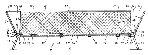
With reference to Figure 1 the net support
structure comprises a pair of uprights 12 which are formed
from tubular aluminium. The uprights 12 are provided with
sleeves 14 which are movable on the uprights 12 but which
are generally retained on the uprights 12. A cross member,
which in this embodiment is a base frame member 20, is
provided to join the upright members 12 and the base frame
member 20 is formed from a plurality of modules 22, 24 and
26. The modules 22, 24 and 26 are also tubular aluminium
members.
The uprights 12 are joined to the base member 20
formed,from the modules 22, 24 and 26 by joining members 30
which are generally in the form of elbows and which have a
pair of sockets 32 and 34. The elbows 30 are also provided
with an additional pair of sockets 36 which support leg
members 38 for stably supporting the net structure on the
ground.
The elbows 30 are best seen in Figures 2 and 3.
The tubular module 26 is provided with sleeves 40
which are permanently fixbd to the ends of the module 26.
The modules 22 and 24 have a fixed sleeve 40 at the end of
the modules which are intended to be the outermost ends of
those modules when the modules are connected together. The
modules 22 are provided with a movable sleeve 14 similar to
the sleeves 14 on uprights 12 and which are movable relative
to the modules 22.
The base member 20 is formed by simply sliding the
free ends of the tubular modules 24 into the sleeves 40 on
module 26. The free ends of the modules 22 are then
inserted into sleeves 40 of the modules 24 with the movable
sleeves 14 on the modules 22 being moved out of the way to
an intermediate gosition on modules 22 ss shown. The
sleeves 14 on the modules 22 play no part in this
configuration. The sleeves 40 on the modules 22 now slot
into sockets 34 on the elbows 30.
An elasticized cord 50 is provided which extends
VI~O 93/01866 :~ a .r ') ;; , ~, PCT/AU92/00087
.., c; ':z ~) , J
through uprights 12 and the modules which make up base
member 20 and is provided with toggles 52 to prevent the
ends of the elasticized cord from entering the uprights 12.
The toggles 52 may also be used to secure net 60 so that net
~60 is suspended between the uprights 12.
Preferably the elasticized cord 50 is passed
through the uprights 12 and the members 20 and the toggles
52 are joined in place so that the uprights 12 and modules
forming the member 20 are joined together. This generally
ties the uprights 12 and modules 22, 24 and 26 together even
when the net structure is not erected. When the net
structure is not erected the modules are just disconnected
from another and from the elbows 30 by slipping the modules
22, 24 and 26 from the respective sleeves and from the
elbows so that they can be folded into side by side
relationship with the elasticized cord still passing through
them and therefore joining them together even in the
collapsed state.
As is best shown in Figure 3 the elbow 30 is
provided with a slot 35 which extends along the entire
length of the elbow from the end of sockets 32 to the end of
socket 34. The slot 35 enables the elasticized cord 50 to
enter the elbow 30 when the uprights 12 and frame members 22
are joined with the elbows 30 so that the elasticized cord
is accommodated in the elbow 30.
The slot 35 in the elbows 30 enables the elbows to
be inserted onto the cord so that the uprights 12 and frame
member 22 can easily inserted into the sockets 32 and 34
with the cord extending through the uprights 12 and the
sockets 22 and can enable the elbow 30 to be disassembled
from the cord when desired to pack up and store or transport
the net support structure.
~ The additional sockets 36 generally form an obtuse
angle with the horizontal so that the leg members 38 are
splayed outwardly to support the frame member 20 and elbows
30 on or above the ground with the uprights extending
upwardly preferably at an angle as shown in Figure l~so that
the net 60 can be easily suspended between them. The cord
WO 93/01866 ~, c° PCI'1AU921i)008'
~ ,~ ,s~y~i) ~~ ~~ ,1 - 6 _
., .r
r '
50 is elasticized so that when the net 60 is suspended by
the cord 50 it applies tension to the upright 12 and the
frame member 20 to tension the structure.
The net 60 is provided with a heading tape 62
through which cord line 64 passes which can be tied onto the
toggles 52 to join the net 60 to the elasticized cords 50.
The heading tape 62 is provided with eyelets 70 to
which are tied tie cords 69. The tie cords 69 can be used
to pull the net 60 downwards to reduce its height and the
tie cords 69 can be tied to base member 20 to hold the net
in this position.
Figure 4 shows a second embodiment where the net
support structure is intended to support the net 60 at a
higher level for playing volleyball, badminton or the like.
In this embodiment the uprights 12 are formed by upright
members identical to those used in the embodiment of Figure
1 and which are referenced 12' in Figure 4 and secondary
uprights 22' which are identical to the modular members 22
used in the horizontal frame member 20 in Figure 1. Thus,
the elbows 30 are simply located between the modules 24 and
modules 22 instead of between the uprights 12 and modul~as
22. In this embodiment the movable sleeve 14 on the upright
member 12 is simply slid up along the upright 12 to expose
the end of the upright 12' so that the end of the upright
12' can be inserted into the fixed sleeve 40 on the end of
the frame member 22'. The movable sleeve 14 on the frame
member 22' simply falls under the influence of gravity to
be retained by socket 32 of elbow 30.
The movable sleeve 14 which is on the uprights 12'
simply falls under the influence of gravity and rests on the
sleeve 40 which is attached to the upright 22' and in which
the end of the tubular upright frame member 12' is received.
The base frame member 20 is formed from the
modular members 24 and 26 which are described with reference
to Figure 1. Thus, the distance between the uprights 12 is
reduced compared to that in Figure 1 but the height of the
net is raised so that the net is now suitable for
volleyball.
PCT/AU92/00087
WO 93/01866 _ 7 _ ~~ y .~. ,.; ~i ) ~l
To secure the net the tie cords 69 tied to the
eyelets 70 in the heading tape 62 are tied onto the toggles
52 to secure the net and shorten the length of the net. The
parts of the net beyond eyelets 70 simply fall free.
Although the uprights 12 and frame member 20 are
shown straight in the drawings they tend to bow slightly
when the net 60 is suspended because of tension applied by
the cord 50.
In alternative embodiments instead of connecting
the uprights 12 and modules 22, 24 and 26 together by
sleeves 40 the modules 22, 24, 26 and the uprights 12 could
be joined by making adjacent modules and uprights of
slightly different diameter tubular material so that the end
of one module is telescopically received into the end of the
adjacent module. The larger diameter module could be
provided with rivets, depressions or the like to act as an
abutment to limit the amount of insertion of the smaller
diameter module.
In another embodiment the uprights 12 and modules
22, 24 and 26 could be of the same diameter and ends could
be swayed to provide an enlarged diameter portion or a small
diameter portion for telescopically joining the modules.
In a further embodiment instead of utilizing the
toggle 52 to prevent the cord 50 from being drawn out of the
uprights 12 and modules 22, 24 and 26 the cord 50 could be
joined to the upper end of the uprights 12 by means of an
insert twhich will be described with reference to figure 7)
which is received and retained in the end of the uprights 12
and which has a hole through which the cord 50 passes and is
tied off. An end cap tto be described with reference to
figure 7> could be located over the uprights 12 to cover the
insert. In this embodiment instead of using the toggle 52
. to secure the net, the net could be provided with a hook or
clasp for securing it to the uprights 12 or a fixture
connected to the uprights or the net could be provided with
a sleeve which is merely slipped over the uprights 12 in
order to locate the net in place.
In the embodiments described above, the elbows 30
(. 5.~
WO 93/01866 r ' ~~~ ~~'' ,~ ~ PCT/AU92100087
~3 \ lr ~'
:~ .,. _ 8 _
are provided with the slots 35 so that the elbows can be
completely removed from the elasticated cord and can be
repositioned between any of the uprights 12, and modules 22,
24 and 26. In an alternative embodiment the slot 35 in the
elbows 30 could be omitted so that the elasticated cord 50
passes through the elbows 30 and the elbows 30 are located
only in one position and remain in that position. In this
embodiment the net structure would be a fixed structure and
a number of configurations would not normally be available.
Thus, the net would be a permanent tennis net with the
elbows 30 fixed between the uprights 12 and modules 22, or a
volleyball net with the elbows 30 fixed between the modules
22' (figure 4) and the modules 24, however, even with the
elbows 30 not provided with slots 35 and permanently fixed
on the elasticated cord 50 in a single position it is still
possible in some instances to alter the configuration of the
net structure to allow different games to be played. For
example, in the case of the volleyball net shown in figure
4, even in the elbow 30 is fixed in place it would be
possible to disconnect the uprights 12' from the modules 22'
and fold the uprights 12' downwardly so that they are
arranged adjacent to the modules 22'. The uprights 12'
could be fixed to the modules 22' by velcro (trade mark)
fastener strips or the like and the net could therefore
extend between the top of the modules 22' to provide a lower
net for playing tennis or the like.
Figure 5 shows an embodiment which is similar to
that of figures 1 and 4 expect that additional support
members 102 are provided between upright 12 and the ends of
legs 38. The additional supports 102 could be tubular
members, elastieated cords or the like. In this embodiment
of the invention the legs 38 are coplanar with the base
member 20 so that the base member 20, the elbow 30 and the
legs 38 sit flat on the ground. The additional support
members 102.securely tie the upright 12 to the legs 38 to
provided added strength and reinforcement for the net. If
the additional supports members 102 are elasticated cords
eyes or the like could be provided on the legs 38 and the
WO 93/01866 ~ ~ -~- '~ ~-' ~~ ~~ PCT/AU92/00087
_ g _
uprights 12 for receiving the ends of the cords. If the
supports are in the form of tubular members then sockets or
elbows could be provided on the legs 38 and the upright 12
in order to receive the ends of the additional supports I02.
With reference to figure 6 a different method of
joining the modules 22, 24, 26, elbow 30 and upright 12 is
shown. In this embodiment of the invention instead of using
the elasticated cord 50 springs are connected between the
modules 22, 24 and 26, the elbow 30 and the uprights 12.
The modules 22, 24, elbow 30 and upright 12 are shown
separated for the ease of illustration. In order to erect
the net the springs 100 simply pull the ends of the modules
22, 24, elbow 30 and upright 12 together so that they abut
the adjacent module, elbow or upright as the case may be, to
securely hold the modules, elbow and upright together. The
springs 100 therefore tension the modules 22, 24, elbow 30
and upright 12 in the same manner as the cord in the earlier
embodiments. In order to collapse the system the modules
22, 24, elbow 30 and upright 12 are simply pulled apart to
stretch the springs 100 as shown in figure 6 and the modules
are folded into a position adjacent one another as in the
earlier embodiment for storage.
In the embodiment described with reference to
figures 1, 4 and 5, the legs 38 are not joined by the cord
50 or any other members to the remaining components of the
net support structure. It would be possible in those
embodiments to join the legs 38 by means of springs (not
shown) to the elbows 30 so that they are always joined to
the structure and can be connected by simply allowing the
springs to pull the legs 38 into the desired supporting
position and collapse by stretching the spring and allowing
the leg 38 to be folded into the collapsed position beside
the base member 20 or upright 12. In yet a further ;.
embodiment instead of using springs to join the legs 38 to
- the elbows 30 separate elasticated cords (not shown) could
be used to perform this function.
Figure 7 shows yet a further embodiment of the
invention in which the upright 12 includes a socket 146 for
WO 93/01$66 ~? h, 4~. t~~ ' PCT/A 1)92/00087
~) '~ t ~ ~ '
- 10 -
receiving additional upright member 148. Elasticated cord
50 is connected to insert 152 located in the uprights 12 by
passing the elasticated cord through a hole (not shown in
the insert 152 and tying the cord off behind the insert 152.
An end cap 154 can be located over the upright 12 to cover
the insert 152 and the tied off cord 50. Elasticated cord
50 joins the upright 12, elbow 30, modules 22, 24 etc. in
the same manner as in the earlier embodiments and tensions
them when the modules and uprights are connected together.
A net such as a tennis can be coupled to the upright 12 by a
hook or other fastener (not shown) which engages an eye or
other fastener (not shown) on the upright 12. If it is
desired to extend the height of the net to play volleyball
or the like the upright 148 is located in the sleeve 146 to .
support the net. Depending upon the height which is desired
for the net and the size of the uprights 148 a number of
uprights 148 could be utilized. Preferably those uprights
are joined by an elasticated cord 51 which is secured to the
lower end of the bottom upright 148 and passes through all
of the uprights 148 and is connected to the top of the upper
upright 148 for joining the uprights 148 and tensioning them
when in the erected state.
The embodiment of figure 7 also shows a method of
connecting the upright 12, elbow 30 and modules 22, 24 etc.
by providing enlarged diameter swaged ends on the elbows 30,
modules 22, 24 etc.
figures 8 to 12 show some additional
configurations which can be produced according to preferred
embodiments of this invention. In each of the
configurations shown in figures 8 to I2 the modules 110 are
the same as the modules 22, 24, 26 and upright 12 previously
described and they can be joined and tensioned by means of
an elasticated cord similar to the cord 50 or by means of
the springs 100 between the modules 110. The modules 110
are joined by any one of the methods previously described
ti. e, by sleeves 40, small and large diameter modules,
modules having small and and large diameter ends etc.),
Elbows (not shown in figures 7, 9, 10 and 11) are provided
W0 93/01866 ~ ; ~. ~ ~~ ~3 ~) PCT/AU92/00087
- 11 -
at all right angled corners. Depending on the nature of the
net support structure the elbows can be provided with
additional sockets for legs supports or the additional
sockets can be omitted if additional legs are not required.
Figure 8 shows a net support structure for
supporting a soccer net. The structure includes base
modules 110a and upper modules 110b (which comprise cross
members) and upright modules 110c. In the preferred
embodiment of the invention the elbows at the corners (not
shown) could be provided with slots similar to the slots 35
so that the elbows can be removed and relocated between any
of the modules 110 to change the dimensions and shape of the
net. The configuration shown in figure 8 is best suited for
soccer or water polo but if the configuration is turned on
its side it could be used as a barrier net for other ball
games or, indeed, the configuration of the net could be
completely altered by merely relocating the elbows between
any of the desired modules to form right angled corners
where desired in order to provide a net support structure of
any desired shape.
The embodiment shown in figure 8 can also be used
to form a cage by the use of two structure of the type shown
in figure 8 and by turning the structures upside down and
locating them side by side so that they effectively form a
cage or race in which cricket, baseball or the like can be
practised.
Figure 9 shows preferred elbows 30a and 30b which
may be incorporated if it is desired to use additional
modules 120 to provide additional support for the net
structure. Elbows 30a would be arranged at the corners C'
and elbows 30b would be arranged at the corners C " . The
elbows 30a and 30b are each provided with sockets 112 so
that a tubular module 120 can be inserted into the sockets
112 to join the elbows and provide additional reinforcement
for the net structure. Once again in the preferred
embodiment the additional support modules 120 could be
completely removed from the net structure or could be joined
to the elbows 30a and 30b by springs or elasticated cords to
PCT/ A U92/OOOA?
WO 93/01866 ~ ,' ~'~ j ~ s 1; \i)
- 12 -
join those modules to the other modules forming the net
support structure.
Figure 10 shows a rebound net formed from modules
110a which form an upper cross member and modules 110b which
form uprights. This module can be used to act as a rebound
net for practising ball games such as golf, tennis and the
like. In this embodiment the net can be formed from two
parts 130 and 132. The net 130 can be a generally loose net
similar to a tennis net so that when a ball hits the net it
drops without rebounding. The net 132 could be a taut net
to act as a rebound net so that if the ball hits that net it
rebounds into play. In this manner a player can practise
tennis by hitting the ball towards the net with a view to
hitting the rebound net 132 to obtain a rebound and to
continue striking the ball to practise tennis strokes. If
the ball hits the lower net 130 it drops dead in a normal
fashion that occurs when a ball hits a conventional tennis
net. This structure is supportEd on legs 38 which are
connected to elbows similar to those figures 2 and 3.
In the embodiment of figure 10 the upright modules
110b can be joined b~~ a pivot hinge so that the upper two
modules 110b can be fulded down adjacent to the lower
modules 110b so that the rebound net 132 is moved out of the
way so that the net support structure can be used as a
normal tennis net.
Figure 11 shows a golf practice net which is
generally of L-shape configuration formed of base modules
110a, uprights 112 and upper members 110c, mid-support
members 110d are also provided. The net support structure
supports a main net 134 and a mid-support protection net 136
for preventing a golf ball from striking the modules 110b
and rebounding towards the player.
Figure 12 shows a net which can be used to divided
a cricket pitch so that cricket can be practised with
bowlers operating from the ends of the pitch at the same
time. In this embodiment cross members 110a are provided
and uprights 110b. The uprights 110b are supported by leg
members 38. A net 140 is suspended by the net support
WO 93/01866 PCT/AU92/0008?
13 -~~, ,f :(_ c.) ~ ii ~ 3
structure and side nets 142 are arranged between the leg
members 38 and the upright members 110b to provide
additional protection.
Nets of the type shown in figures 10, 11 and 12
can be used as backstops, for other ball games such as
baseball, softball and the like.
The nets which are connected to the net support
structure shown in figures 8 to 12 can be joined to the
modules which form the net support structure by hooks, ties
or any suitable fasteners such as velcro (trade mark)
fasteners. Alternatively, an elasticated cord could be
threaded through the net and wrapped around the modules
which make up the net support structure in order to secure
the net in place. When the net support structures are
collapsed the net can be removed from the structure or can
be left attached to the structure and simply folded up with
the modules for storage.
Since modifications within the spirit and scope of
the invention may readily be effected by persons skilled
within the art, it is to be understood that this invention
is not limited to the particular embodiments described by
way of example hereinabove.