Note: Descriptions are shown in the official language in which they were submitted.
21~3702
APPARATUS AND METHOD FOR MACE~INING A GEAR SHAPE
BACKGROUND OF TZIE INVENTION
1. Field of the Invention
The prcsent invention relates to an apparatus and a
method for machining a workpiece wlth a form tool to produce
a finished product of a gear shape and measuring it.
2. Description of the Related Art
Gears are important components of a mac~line for
transmitting motion by meshing t~leir teeth together one after
another. Particularly, since the gears have capabilities of
rotary motion of a precise speed ratio and cfficiently
transmitting large power with an extremely small structure,
tlley are used in very wide number of fields, from the small
gears of measuring instruments, watches, etc., to medium size
gears of automobile transmission gears to the large gears
used as reduction gears of a several ten thousand horse power
marine turbine.
Generally, how little tile gears cause vibration and
nolse to occur depends on ho~ accurately th~y are machined,
and improvement in the machining accuracy have been demanded.
Par ticularly recently, improvement in the machining accuracy
of gears to exclude vibration and no~se sources is required
~.
2I137~2
in the atltomobile field in which the users attach importance
to dwell~ng ability.
Hitllerto, processes such as a machining process with a
gear cut t;er, a forging process, and an electric dlscharge
machining process have been used to form gears; for reasons
of productivity, an extruding forging process and a sinter
forging ~rocess are adopted whereby high-volume production of
gears cah be performed comparatively easily at low costs.
For forglng, the accuracy of forming dies directly affects
gear accuracy, thus it is important to obtain accurate
forging. The forging dies are machined by electric discharge
r~ h1n~ng which is applied independently of the mechanical
strength of forging die material and is capable of accurate
machining. An attempt has been made to improve the rn~t~h in~ng
accuracy by various methods. For example, disclosed in
Japanese Utility Model Laid-Open No.Sho 61-5528 is an
electric discharge machining electrode with a roughing
electrode and a finishing electrode located on one common
electrode shaft whereby the finished machining accuracy of a
gear sllape can be improved. Described in Japanese Patent
Laid-Open No.Hei 4-152025 is an electric discharge machining
process of forging dies that can follow various specification
changes of gears by forming the electric discharge machining
electrode like a spur gear and changing the thickness of an
elcctrode section formed on the gear tip.
.
21137D2
In the eonventional electric discharge maehining of a
gear shape, a workpiece is electric-discharge-machined to
form the gear shape while a form eleetrode for electrie
disellarge machining ~1aving the same shape as the gear shape
to b~ forn~ed is moved in t~le axial dircction of the
workpieee, namely, the gear shape to be formed. At this
time, if 1,he eleetric discharge machining electrode has a
male gear shape, a female gear is formed; if the electrode
has a fem~le gear shape, a male gear is formed.
Elowever, in the conventional electric discharge
machining process of a gear shape, the form electrode for
electric ~ischarge machining moves in the axial direetion of
the gear -~or r~hin~n~ while the electrode and tlle workpiece
approach each other at spacing of 0 . 02-0 . 05 mm via a
proeessing liquid ( insulating liquid sueh as kerosene or pure
water), thus it is diffieult to exclude sludge; the sludge
adheres to the work face or the electric discharge machining
electrode and lowers insulation of t~1e processing liquid,
lowering machining accuracy by an external source. Just
after electric discharge machining starts or ~ust before it
terminates, namely, when only a part of the electric
diseharge maehining eleetrode approaches the workpiece,
diseharge eoneentrates on a part of the approaeh region of
the workpieee and t11e eleetrie discharge machining electrode;
the dise~arge condition ~ust after tlle electric discharge
2113702
machining starts or fust before it terminates differs from
that at the time of stationary machining time, namely, when
the entire electric discharge machining electrode and the
workpiece approach each other uniformly. As a result,
discharge concentrates around the entrance and exit of the
electric discharge machining electrode because the area of
the electric discharge machining electrode approaching the
workpiece is small, and the workpiece is meltcd too much,
causing the work face to change, resulting in lowering the
accuracy ~f the gear shape.
Further, postprocess steps such as grinding, lapping,
and shape measurement are generally required; t~le workplece
is again chucked at each step and a handling error occurs in
addition l;o a mechanical work error, further lowering the
accuracy of the gear shape.
SUMMARY Ol~ THE INYENTION
Accordingly, it is a first obfect of tlle present
invention to provide an apparatus and a method ror machining
a gear shape whereby a workpiece and a form tool, such as a
form electrode, are synchronously moved at a mesh assumed
position for machining the gear shape and easily excluding
sludge, thereby improving the mac~lining accuracy of the gear
shap e .
2113702
It i8 a second ob~ect of the present invention to
provide ar~ apparatus ard a method for machining a gear shape
whereby w~ th a workpiece chucked, mesh synchronous move of
the workpiece and various tools is performed for consistent
machining from material to completion of the gear shape,
thereby eclsily excluding sludge and removing a handling
error, and tllereby improving the machining accuracy of the
gear shape.
It is a third obJect of the present invention to provide
an apparal;us and a method for machining a gear shape whereby
with a workpiece chucked, the gear shape can be measured as
the final step of machining the gear shape.
In order to achieve the aforementioned ob~ects, in
accordance with the first aspect of the present invention,
there is provided an apparatus for machining a gear shape
comprisin~ a chuck for pivotally supporting a workpiece, a
mechanism for rotating the chuck, a mechanism for moving the
chuck in an~ desired direction on a plane, a holder for
pivotally supporting a form tool of a gear shape used to
machine the workpiece, a mechanism for rotating the holder, a
mechanism for sliding the holder in the direction vertical to
a chuck movement plane, and a control section which controls
the chuck rotation mechanism, the chuck move m~chanism, the
holder rotation mechanism, and the holder sliding mechanism
for causing the form tool to approach a mesll assumed position
.
2113702
with the workpiece, rotatlng the workpiece and the form tool
syncllrono~tsly, and applying cut amount control between both
axes of t~le workpiece and the form tool, thereby machining
the workp~ ece with the form tool .
The lhorm tool o~ a gear shape is made to approach the
pivotally supported workpiece and they are rotated
synchronollsly at a m~sh assumed position. At the same time,
while cut amount control is applied between both ~xes of the
workpiece and the form tool, t~le workpiece is machined with
the form l;ool. Thercfore, the relative positional
relations}lip between the workpiece and the form tool of a
gear shape always changes and the approach part of both
always becomes linear, enabling sludge to be casily excluded.
Also, the approach distance between t~le workpiece and the
form tool of the gear shape can always be made constant. As
a result, the machining conditions always become constant
independently of external sources, and an accurate gear shape
can be provided.
In accordance with the second aspect of the present
invention, there is provided an apparatus for laeasuring a
gear shape comprising a chuck for pivotally supporting a
workpiece, a mechanism for rotating the chuck, a mechanism
for moving the chuck in any desired direction on a plane, a
form master gear having a displacement section which carries
out displacement in response to the shape of t~le workpiece, a
2113702
holdcr fol pivotally supporting the form master gear, a
control s~ction which controls the chuck rotation mechanism
and the clluck movement mechanism for causing the workpiece
and the form naster gear to be meshed together and causing
the form master gear to follow the rotation of the workpiece,
and an error detection section which detects displacement of
the displacement section of the form master gear for
detecting a shape error of the workpiece.
The eorm master gear which can carry out displacement in
response to a delicate shape change rotates following the
workpiece which rotates. Therefore, the error detection
section can efficiently detect displacement of the form
master gear rotating following the workpiece for precisely
detecting a shape error of the workpiece.
In accordance with the third aspect of the present
invention, there is provided an apparatus for measuring a
gear shape comprising a chuck for pivotally supporting a
workpiece, a mechanism for rotating the chuck, a mechanism
for moving the chuck in any desired direction on a plane, a
form master gear having a displacement section which carries
out displacement in response to the shape of the workpiece, a
holder for pivotally supporting the form master gear, a
mechanism for rotating the holder, a control section which
controls the chuck rotation mechanism, the clluck move
mechanis~i, and the holder rotation mechanism for causing the
21~3702
workpiece and the form master gear to be meshed together on
an ideal mesh path and to be separately rotated -~or relative
motion of the form master gear and the workpiec~, and an
error detcction section which detects displacement of tlle
form mastcr gear and the workpiece with respect to the ideal
mesh path for measuring a shape error of the workpiece and
the form master gear.
The ~orm master gear and the workpiece are rotated
separately and are meshed together and moved on the ideal
mesh path. As a result, push pressure in t~lC circumferential
direction applied between the form master gear and the
workpiece can be excluded. Therefore, delicate displacement
of the fo~m master gear caused by a change in the workpiece
shape can be precisely detected by the detection section for
measuring the gear shape more stably.
In accordance with the fourth aspect of the present
invention, there is provided an apparatus for machining a
gear shape comprlsing a chuck for pivotally supporting a
workpiece, a mechanism for rotating the chuck, a mechanism
for moYing the chuck in any desired direction on a plane, a
holder for holding a form tool, the ~lolder being disposed
movably to any desired position and able to be rotated, a
mechanism for rotating the holder, a first eccentric ring,
with the axle center of the internal circumfcrence of the
ring being eccentric to that of the external ~ircumference of
21137D2
the ring, for holding the holder on the internal
circumference, at least one contour eccentric ring disposed
for holdir~g the first eccentric ring on the internal
circumference of the contour eccentric ring, a mechanism for
sliding tlle holder in the dlrectLon vertical to a chuck
movement i~lane, and a control section which controls the
chuck rot~ltion mechanism, the chuck movement mechanism, the
holder rotation mechanism, and t~le holder sliding mechanism,
and controls rotation amounts of the f irst eccentric ring and
the contollr eccentric ring for causing the form tool to
approach a mesh assumed position with the workpiece, rotating
the workpLece and the form tool synchronously, and applying
cut amount control between both axes of the workpiece and the
form tool, thereby machining the workpiece with the form
tool .
The holder holding the form tool is disposed slidably in
any desired direction with respect to the machine center of
the machining apparatus, and is held on the internal
circumference of the first eccentric ring with the axle
center of the internal circumference being eccentric to that
of the external circumference. Further, the first eccentric
ring is held on the internal circumference of the contour
eccentric ring having the eccentric internal circumference.
The first eccentric ring and the contour eccentric ring are
eccentrically rotated separately by the control section,
211370~
thercby mQving the holder held by the first eccentric ring
along any desired movement pat~l.
Thercfore, the ~lolder fixing the form tool can be moved
Wit~l any (lesired eccentric amount and at any desired speed by
eccentric rotary motion of the first eccentric ring, and
relative Dlotion of the workpiece and the form tool can be
executed smoothly. As a result, the workpiece can be
machined smoot~lly to provide a smooth machined s~lape of the
workp i ece .
In accordance with the fifth aspect of the present
invention, there is provided an apparatus for measuring a
gear shape comprising a chuck for pivotally supporting a
workpiece, a mechanism for rotating tile chuck, a mechanism
for moving the chuck in any desired direction on a plane, a
form master gear having a displacement section which carries
out displacement in response to the shape of thc workpiece, a
rotatable holder for holding the form master gear and being
disposed movably to any desired position, a first eccentric
ring, with the axle center of the internal circumference of
the ring being eccentric to that of t~le external
circumference of the ring, for holding the holder on the
internal circumference, at least one contour eccentric ring
disposed for holding the first eccentric ring on the internal
circumference of the contour eccentric ring, a control
section which controls the c~luck rotation mechanism and the
2113702
chuck movement mechanism and controls rotation amounts of the
first eccentric ring and the contour eccentric ring for
causing the workpiece and the form master gear to be meshed
together and causing the form master gear to follow the
rotation of the workpiece, and an error detection section
whic~l detects displacement of the displacement section of the
form master gear for detecting a shape error of the
workp i ece _
Therefore, the holder holding the form master gear can
be moved ~yith any desired eccentric amount arLd at any desired
speed by ~ccentric rotary motion of the eccentric ring, and
relative Dlotion of the workp~.ece and tlle form master gear can
be executed smoothly. The displacement section of the form
master gear can respond precisely to a delicate shape change
of the workpiece for measuring the gear shape more precisely.
In accordance with the sixth aspect of the present
invention, there is provided an apparatus for measuring a
gear shape comprising a chuck for pivotally supporting a
workpiece, a mechanism for rotating tlle chuck, a mechanism
for movin~ the chuck in any desired direction on a plane, a
form master gear having a displacement section which carries
out displ~lcement in response to t~le shape of the workpiece, a
rotatable holder for holding the form master gear and being
disposed ~novably to any desired position, a mechanism for
rotating the holder, a first eccentric ring, with the axle
11
2113702
center of the internal circumference of the ring being
eccentric to that of the external circumference of the ring,
for ~loldir~g the holder on the internal clrcumference, at
least one contour eccentric ring disposed for holding the
first ecc~ntric ring on the internal circumference of the
contour eccentric ring, a control section which controls the
chuck rotcLtion mechanism, the chuck movement mechanism, and
the holder rotation mechanism and controls rotation amounts
of t~le first eccentric ring and t~le contour eccentric ring
for causillg the workpiece and t~le form master gear to be
meshed toFether on an ideal mesh path and to be separately
rotated for relative motion of the form master gear and the
workpiece, and an error detection sectlon which detects
displacement of the form master gear and the workpiece with
respect to the ideal mesh path for measuring a shape error of
the workplece and the form master gear.
The holder holding the form master gear can be moved
with any desired eccentric amount and at any desired speed by
eccentric rotary motion of tile eccentric ring, and external
force unnecessary for measuremcnt, applied to the form master
gear can be excluded. Therefore, relative motion of the
workpiece and the form master gear can be executed more
smoothly. The displacement section of the form master gear
can respond precisely to a delicate shape change of the
workpiece for measuring tlle gear shape more precisely.
12
2ll37a2
In accordance with the seventh aspect of the present
invention, there i9 provided an apparatus for machining a
gear shap~ comprising a chuck for pivotally supporting a
workpiece, a mechanism for moving the chuck in any desired
direction on a plane, a unit for lapping the workpiece, a
holder fo~ pivotally supporting the lapping unit, a mechanism
for 61idillg the holder in the direction vertical to a chuck
movement l)lane, and a control section which controls the
chuck movement mechanism and the holder sliding mechanism for
moving tlle lapping unit up and down against the workpiece,
thereby lapping the workpiece. The lapping unit has a
supporter substantially like a l~Lllar and a lapping tool
attac~led to the axle center of the supporter in such a way
that the lapping tool can be opened and closed. The lapping
tool has a proJection having a lapping grindstone.
For a gear formed with multiple gears like steps, if the
gear is an external gear, the lapping tool is opened and the
lapping unit is located at a predetermined position in the
axial direction, then lapping is performed while the lapping
tool is gradually closed. The lapping tool, which is
provided with the proJection, enables lapping the gear
subJected to interference of another member when viewed from
the installation position of the lapping unit. Therefore,
accurate lapping can be performed up to the stepped part,
The lapping unit is moved to the position of the gear being
13
.
2113~02
machlned with the lapping tool opened, and thus can be easily
moved to the machining position.
For ~.nternal gears, the lapping tool enables lapping the
gear sub,~cted to interference of anot~ler member when viewed
from the installation position of the lapping unit; accurate
lapping c~Ln be performed up to t~le stepped part. The lapping
unit can be easily moved to the machining position.
In accordance with the eighth aspect of the present
invention, there is provided a method of machining a gear
shape comprising the steps of causing a form tool of a gear
shape to approach a workpiece pivotally supported by a chuck,
rotating the workpiece and t~le form tool synchronously at a
mesh assulned position, applying cut amount control between
both axes of the workpiece and t~le form tool, and machining
the workpiece with the form tool to provide a desired gear
shap e .
The form tool of gear shape is made to approach the
workpiece pivotally supported and they are rotated
synchronously at the mesh assumed position. At the same
time, while cut amount control is applied between both axes
of the workpiece and the form tool, the workpiece is machined
with the form tool. Thercfore, the relative positional
relationship between the workpiece and the form tool of gear
shape always changes and tlle approac~l part of both always
becomes linear, enabling sludge to bc easily excluded. Also,
14
2113~2
the appro~lch distance between the workpiece and the form tool
of gear silape can always be made constant. T~lerefore, the
rnç7~hf n ing conditions always become constant independently of
external 60urces, and accurate gear shape can be performed.
In accordance with the ninth aspect of the present
invention, there is provided a method comprising the steps
of, with a workpiece chucked, while changing form tools in
sequence, electric discharge machining, rotating the
workpiece and form tool synchronously at a mesh assumed
position, grinding and lapping the workpiece, and measuring
the workp Lece shape with a measuring tool .
When grinding and lapping are performed, the contact
parts of the workpiece and tools also become linear and
sludge cah be easily excluded for stable machining. With the
workpiece chucked, electric discharge machining can be
followed by grinding, lapping, and measuring of the gear
shape; a sequence of the machining steps of the gear shape
can be performed with a handling error removed.
In accordance with the tenth aspect of the present
invention, there is provided a method of machining a gear
shape comprising the steps of causing a form tool and a
workpiece held by a chuck to approach each other, rotating
the workp iece and the form tool synchronously at a mesh
assumed position, applying cut amount control between both
axes of the workpiece and the form tool, and machining the
2~137~2
workpiece with the form tool to provide a desired gear shape,
wherein a holder for holding the form tool and being movable
to any desired position is held on the internal
circumference of a first eccentric ring with the axle center
of the inl,ernal circumference being eccentric to that of the
external circumference and rotation amounts of the first
ecccntric ring and of at least one contour eccer,tric ring for
holding tlle first ecce~tric ring on the internal
circumfercnce of the contour eccentric ring arc separately
controlle(l, thereby moving the holder along any dcsired move
path and (letermining the machined shape of th~ workpiece by
the shape of the form tool and the move path of the holder,
The rotation amounts of the -î irst eccentric ring and the
contour eccentric ring are controlled separately, thereby
enabling l~he holder held by the first eccentric ring to be
moved alollg any desired move path: various workpiece shapes
can be easily machined by any desired relative motion of the
form tool and the workpiece. Therefore, relative motion of
the workpi.ece and the form tool can be executed smoothly, and
the machined face of the workpiece can be made smooth to
provide an accurate machined shape of the workpiece.
In accordance with the eleventh aspect of the present
invention, there is provided a method of measuring a gear
shape wherein when a pivotally supported workpiece of gear
shape and a pivotally supported form master gear for
16
21~3702
measuring the gear sllape are meshed together and moved on an
ideal mesll path, displacement of the form master gear and the
workpiece with respect to the ideal mesh path is detected for
measuring a shape error of the workpiece.
Since the form master gear and t~le workpiece are meshed
together and moved on the ideal mesh path, push pressure in
the circumferential direction applied between the form master
gear and l;he workpiece can be excluded. Therefore, delicate
displacement of the form master gear caused by a change in
the workp~ece shape can be precisely detected by the
detection section for measuring the gear shape stably.
In accordance with the twelfth aspect of tile present
invention, there is provided a method of measuring a gear
shape whe]-ein when a pivotally supported workpiece of gear
shape and a pivotally supported form master gear which is
thin in tlle tooth trace direction for measuring the gear
shape are meshed together and moved on an ideal mesh path and
the form Inaster gear is moved in ~he tooth trace direction of
the workpiece, displacement of the form master gear and the
workpiece with respect to tlle ideal mcsh path is detected for
measuring a shape error of the workpiece and thc form master
gear .
While the form master gear thin in the tooth trace
direction and the workpiece are meshed together and moved on
the ideal move path and th~ form master gear is moved in the
17
2113702
tOOt~l trace direction of the workpiece, displacement of the
form master gear and the workpiece wi th respect to the ideal
mcsh path is detected by the detection section. Therefore,
tooth trace accuracy as well as shape accuracy of the gear
shape can be detected; an accurate gear shape can be
provided .
BRIEF DESCRIPTION OF TEIE DRAWINGS
The objects, features and advantages of the present
invention will become more apparent from the consideratlon of
the following detailed description, taken in conjunction with
the accompanying drawings, in wllich:
Figure 1 is a schematic drawing of an apparatus for
machining a gear shape according to t~le present invention;
Figure 2 is a partial sectional side view illustrating
the position relationship between a workpiece and a form tool
(form electrode) in the apparatus for machining a gear shape
according to a first embodiment of the present invention;
Figure 3 is an illustration showing the positional
relationship between a workpiece and a form tool (form
electrode) in the apparatus for machining a gear shape
according to the first embodiment of the present invention;
Figure 4 is an illustration showing the configuration
for carrying out mesh assumed synchronous movement in the
18
2113702
ap~aratus for machining a gear shape according to the present
invent i on;
Figure 5 is a partial sectional side view illustrating
the position relationship between a workpiece and a form tool
(form electrode) in the apparatus for machining a gear shape
according to a second embodiment o-~ the present invention;
Figu~e 6 is an illustration showing the position
relationship between a workpiece and a form tool (form
electrode) in the apparatus for machining a gear shape
according to the second embodiment o~ the present invention;
Figure 7 is a partial sectional side view illustrating
the positional relationship between a workpiece and a form
tool (form electrode) in the apparatus for machining a gear
shape according to a third embodiment of the present
invention;
Figure 8 i8 an illustration showing t~le positional
relationship between a workpiece and a form tool (form
electrode) in the apparatus for machining a gear shape
according to the third embodiment of the present invention;
Figure 9 is an illustration giving an example of the
form of a grinding wheel or lapping grindstone used with the
apparatus for machining a gear shape according to the present
invent i on;
Figures 10 (A), lO(B), and lO(C) are illustrations
giving other e~amples of tlle form of a grinding wheel or
19
2113~02
lapping grindstone used with the apparatus for machining a
gear shape according to the present invention;
Figure 11 is a sectional view showing an eccentric
rotation mechanism in the apparatus for machining a gear
shape accDrding to a fourth embodiment of the present
invent i on;
Figure 12 is a partial sectional view of eccer~tric rings
of the eccentric rotation mechanism in the apparatus for
machining a gear shape according to the fourth embodiment of
the prese~t invention;
Figure 13 is an illustration showing a movement path of
the rotation center of a holder of the eccentric rotation
mechanism in the apparatus for machining a gear shape
according to the fourth embodiment of the present invention;
Figure 14 is an illustration showing the configuration
for carrying out eccentric synchronous movemcnt in the
machining apparatus of a gear shape according to the fourth
embodiment of the present invention;
Figure 15 a partial sectional side view illustrating the
positional relationship between a workpiece and a form
master gear in a measuring method of a gear shape according
to the invention;
Figure 16 is a partial sectional view illustrating a
measuring tool in an apparatus for measuring a gear shape
according to a fifth embodiment O-r the present invention;
.,
2113~02
Figu~ e 17 is a low end view illustrating the measuring
tool in tile apparatus for measuring a gear shape according to
the fifth embodiment of the present invention;
Figu~e 18 is an illustrating showing the positional
relationsllip between a workpiece and a form master gear in an
apparatus for measuring a gear shape according to the sixth
embodiment of the present invention;
Figu~e 19 is a partial sectional view of a measuring
tool in the apparatus for measuring a gear shape according to
the sixth embodiment of the present invention;
Figure 20 is an illustration showing the installation
stat~ of minute displacement detection sensors of the
measuring tool in the apparatus for m~asuring a gear shape
according to the si~tll embodiment of the present invention;
Figure 21 is an illustration showing the mesh state of a
workpiece and form master gear in the apparatus for measuring
a gear shape according to the sixth ~mbodiment of the present
invent i on;
Figure 22 is an illustration showing the mesh state of a
workpiece and form master gear of another shape in the
apparatus for measuring a gear shape according to the sixth
embodiment of the present invention:
Figure 23 (A), 23(B), and 23(C) illustrate the gear tip
shapes of form master gear in an apparatus for measuring a
gear shape according to the sixth embodiment of ~he present
21
2113702
invent i on;
Figu~-e 24 is a partial sectional view of another
measuring tool in the apparatus for measuring a gear shape
according to t~le sixtll embodiment of the present invention;
Figure 25 is an illustration showing the configuration
for carrying out mesh movement along an ideal mesh path in
the appar~tus for measuring a gear shape according to the
fifth arld sixth embodiments of the present invention;
Figure 26 (A), 26(B), and 26(C) are examples of gears
having special shapes that can be macllined by a lapping unit
according to a seventh embodiment of the present invention;
Figure 27 is a partial sectional view of a lapping unit
according to the seventh embodiment of the present invention;
Figure 28 is a partial sectional view of a lapping unit
according to an eighth embodiment of the present invention;
Figure 29 is a partial sectional view of a lapping unit
indicating the state in which a lapping tool is closed
according to a ninth embodiment of the present invention;
Flgure 30 is a partial sectional view of the lapping
unit indicating the state in which the lapping tool opens
according to the ninth embodiment of the present invention;
Figure 31 (A) is a partial sectional view of a lapping
unit according to a tenth embodiment of the present
invention;
Figure 31 (B) is an end vi~w of the lapping unit
22
211~702
according to the tenth embodiment of the present invention;
Figu~e 32 is a partial sectional view of a lapping unit
according to an eleventh embodiment of the present invention;
Figure 33 is a partial sectional view of a lapping unit
according to a twelfth embodiment of the present invention;
Figure 34 (A) is a partial sectional view of a lapping
unit according to a thirteenth embodiment of the present
invention; and
Figure 34 (B) is an end view of the lapping unit
according to the thirteenth embodiment of the present
invention;
DESCRIPTION OF THE PREFERRED EMBODIMENTS
Referring now to the accompanying drawings, there
are shown preferred embodiments of the present invention.
Figure 1 shows a schematic drawing of an apparatus for
carrying out a method for machining a gear shape according to
the invention.
App~lratus 1 is adapted to sequentially change a
pluralit~ of tools, such as an electrode for
electric discharge machining, a grinding wheel for grinding,
a lapping grindstone for lapping, and a tool for measuring
the shape of a workpiece, with the workpiece chucked for
performillg a sequence of machining steps, such as electric
23
-- -- --
2113~2
discharge machining, grinding, and lapping, from material to
completion of a gear shape, and accuracy measurement. A tool
4 (an electrode 4a for electric discharge machining, a
grinding ~vheel 4b for grinding, a lapping grindstone 4c for
lapping, a measuring tool 4d for accuracy measurement, or the
like; here the tools are substantially of the same form, and
are shown on the same drawing) supplied by an automatic tool
changer 2 having a robot arm 2a is held by a holder 8
interlocked with an inde~ rotation unit 6 having an index
positioning device. The holder 8 and the index rotation unit
6 are incorporated in a rotary head section 12 moving up and
down along a column lO. A workpiece 14 to be machined is
flxed by a chuck 16, which has a plurality of clicks 16a and
can be rotated by a rotation mechanism (not shown) such as a
servo motor. The chuck 16 is pivotally mounted on a base 18,
which incorporates a chuck rotation mechanism. The base 18
is held b.~ a saddle table 20 having a drive mechanism that
can be moved in the X and Y axis directions. A processing
tank 22, which surrounds the workpiece 14, the chuck 16, and
the base 18 to secure the worker against danger during
r~h~n~ng and temporarily stores a processing liquid in,~ected
or supplied to the workpiece 14, is provided on the top of
the saddle table 20. The processing liquid conforming to
machining is supplied to the processing ~ank 22 from a
processing liquid supply unit 24, which also has capabilities
24
2113702
of storing, depositing, filtering, etc., of the processing
liquld. The apparatus 1 is provided with a controller 25
such as a centralized controller, etc., in addition to the
component~ mentioned above.
An electric discharge machining method of an internal
gear shape is described as a first embodiment according to
the apparatus 1 having the configuration wit~l reference to
Figures 2 and 3.
The invention is first characterized by the fact that
the form electrode 4a of gear shape as the tool 4 is made to
approach the workpiece 14 pivotally supported and that the
workpiece 14 and the form electrode 4a are rotated while they
are synchronized at mesh assumed positions and at the same
time, that electric discharge machining is performed to
provide a desired gear shape while cut amount control is
app].ied between botll axes of the workpiece 14 and the form
electrodc 4a.
The workpiece 14 and the form electrode 4a are rotated
in synchronization with each ot~ler as a planet pinion gear
and an i~lternal gear of a planet gear mechanism are moved
while tlley are meshing with each othcr. As shown in Figures
2 and 3, the form electrode 4a, which has a predetermined
gear shape and is attached to the holder 8 at the machine
center Or the apparatus 1, rotates on its axis in the arrow
L direction in Figure 3 while it performs electric discharge
.
2113702
machining on the internal circumference of the workpiece 14
held by t~le clicks 16a of the chuck 16. At the time, the
workpiece 14 is pivotally mounted on the base 18 and rotates
in the arrow L2 direction in Figure 3 in synchronization with
rotai:ion of tllc form electrode 4a. At the time, the chuck 16
is rotated by a workpiece rotating servo motor 28 which has a
chuck rot~ltion position and speed detection section 26 and
can perfo~m fecdback con~rol for the rotation speed and
position of the chuck 16. During electric discharge
machining, like normal electric discharge machining, the
processin~ tank 22 (see Figure 1) is filled with a processing
liquid, s~lch as kerosene or pure water, and the workpiece 14
and the form electrode 4a are put into tlle processing liquid.
Electric discharge machining conditions are determined and
the workpiece 14 and the form electrode 4a are moved
synchronously at mesh assumed positions. At this time, the
saddle table 20 (see Figure 1) on which the base 18 is
installed is fed b~ a predetermined distance consecutively in
sequence in the arrow X direction in Figure 3, for e~ample,
to make an electric discharge machining allowance.
Therefore, the mesh assumed positions of the workpiece 14 and
the form electrode 4a becomc deep gradually deeper and the
portions through which the form electrode 4a has passed are
removed, thereby forming a gear shape on the internal
circumference of the workpiece 14.
26
2113702
Figure 4 is a schematic drawing showing the
configuration for rotating the workpiece ~4 and the tool 4
while synchronizing them at mesh assumed positions in the
apparatus for machining a gear shape according to the present
invention. For example, for electric discharge machining,
the form ~lectrode 4a is attached to the holder 8 as the tool
4 and held by the rotary head section 12 containing the tool
rotating servo motor 32 haYing the tool rotation position and
speed detection section 30.
On the other hand, the workpiece 14 is held by the chuck
16 which is pivotally mounted on the base 18 and has a
plurality of clicks 16a and is rotated in synchronization
with rotation of the form electrode 4a by the workpiece
rotating servo motor 28 which has the chuck rotation position
and speed detection section 26 and can perform feedback
control for the rotation speed and position of the chuck 16.
Further, the base 18 on which t~le chuck 16 is installed
is driver~ in the left or right direction by an X direction
feed mec~lanism. If the X direction feed mechanism consists
of, for cxample, a ball screw 44, the base 18 fixed to a
female screw section 42 is driven in the X direction (left or
right dil ection in the figure) accurately by a base driving
servo mol;or 48 which is engaged with a bed 50 and has a base
rotation position and speed detection section 46. The saddle
table 20 on which t~le base 18 is installed is driven back and
27
2113702
forth by a Y direction feed mechanism. If the Y direction
feed mechr~nism consists of, for example, a ball screw, the
saddle table 20 fixed to a female screw section 52 is driverl
in the Y direction (back and forth in the figure) accurately
by a saddle table driving servo motor 56 which has a saddle
table rotation position and speed detection section 54. The
direction and amount of motion of the workpiece 14 can be
changed as desired by combining drive in the X direction and
in the Y dircction.
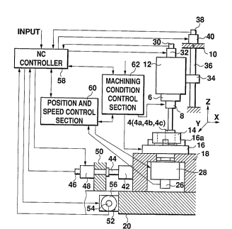
The servo motors 28, 32, 48, and 56 are controlled by an
NC controller 58 so that the related servo motors perform
predetermined operation in conJunction with each other.
Particularly during electric discharge machining, the
rotation speed of the tool rotating servo motor 32 for
driving the form electrode 4a is kept accurate by the NC
controll~ 58 and t~le rotation speed of the workpiece
rotating servo motor 28 operating so as to follow the form
eleetrod~ 4a is controlled by a position and speed eontrol
seetion ~0 whieh always deteets the rotatiQn position and
speed of the workpiece 14, feeds them back, and performs
comparison operation for control; machining is performed by a
machining condition control section 62 which controls
maehinin~ eonditions while moving with signals Or the NC
eontroller 58 and t~le position and speed control seetion 60.
Since the workpieee 14 and the form eleetrode 4a perform mesh
28
21137~2
assumed synchronous move together while they are rotating
mutuall y, the relative positional relationship between them
always changes and the approach portion of the workpiece 14
and the form electrode 4a always becomes linear, enabling
sludge to be discharged or removed easily and a processing
liquid to circulate smoothly. Since mesh assumed synchronous
move is performed, the approach amount oi' the workpiece and
the form electrode of a gear shape can always be made
constaht and change of electric discharge machining
conditions caused by an external source can be suppressed.
Therefore, a gear shape can be electric- discharge-machined
accurately .
For example, even an internal stepped gear shape whose
bottom has a larger inner diameter than the top can be
electric-discharge-machined easily by a similar machining
me tho d .
Further, in the embodiment, t~le rotary head section 12
is dri ven up and down by a Z direction feed mechanism to
apply relative movement in t~le tooth trace direction between
the w~rkpiece 14 and the form electrode 4a to machine a
stepp~d gear shape. If the Z direction feed mechanism
consists of, for example, a ball screw 36, the rotary head
section 12 fixed to a female screw section 34 is driven ln
the Z direction (upward and downward in the figure) smoothly
by a llead section driving servo motor 40 which is engaged
29
2113102
with tlle column 10 and has a head section rotation position
and speed detection section 33.
Figures 5 and 6 show a method for electric discharge
machining an external gear shape as a second embodiment. The
machinlng method of the external gear shape can be embodied
by the same apparatus and control method as the electric
discharge machining method of the internal gear shape
accord;Lng to the first embodiment except that a form
electrode 4a-1 for electric discharge r~ hin~nF and a
workpiece 14-1 perform mesh assumed synchronous movement
while the i~orm eleGtrode 4a-1 is rotating on the external
circuml?er~nce of thc workpiece 14-1 in t~le opposite direction
to t~le workpiece 14-1 (the form electrode 4a-1 rotates in the
L direction in Figure 6 and the workpiece 14-1 rotates in t~le
R direction in Figure 6). In this case, by feeding the chuck
16 by a predetermined distance consecutively in sequence in
the arrow X' direction in Figure 6 as an electric discharge
machining allowance, the mesh assumed positions of the
workpiece 14-1 and the form electrode 4a-1 become gradually
deeper and the portions through which the form electrode
4a-1 has passed are removed, thereby forming a gear shape on
the external circumference of the workpiece 14-1.
Figures 7 and 8 show a method for electric discharge
machining a bevel gear shape as a third embodiment. The
machining method of the bevel gear shape can be embodied by
21137~2
tlle salhe apparatus and control metilod as the electric
dischal ge machining method of the external gear shape
accord~ng to the second embodiment except that a workpiece
14-2 is located inclined by angle H with respect to a form
electrode 4a-2 in response to an axial angle ~ of the bevel
gear sllape, as shown in Figures 7 and 8. This means that the
rotation drive means of the workpi~ce 14 such as chuck 16,
base 18, and saddle table 20 are disposed inclined by angle
with respect to the rotation axis of the form electrode 4a.
In this case, the chuck 16 moves by a predetermined distance
conseclltively in sequence in the arrow Z direction in Figure
7 as a~ electric discharge machining allowance, whereby the
mesh assumed positions of the workpiece 14-2 and the form
electrode 4a-2 become gradually deeper and the portions
through which the form electrode 4a-2 has passed are removed,
thereby forming a bevel gear shape on the external
circumference of the workpiece 14-2. In this case, similar
machining can also be performed by moving the form electrode
4a-2 by a predetermined distance consecutively in sequence in
the arrow Z ' direction in Figure 7 by the tool rotating servo
motor 32 having the Z direction feed mechanism (see Figure
4) .
As described above, the position relationship between
the form electrode and workpiece is changed in response to a
desired gear shape by crossing t~le rotation axes of the form
31
.
21~37~2
electrode and workpiece at any desired angle ~ or offsetting
the rotation axes or performing both, and mesh assumed
synchronous move of the workpiece and the electrode formed to
a desired gear shape is performed, thereby machining spur
gears, helical gears, double helical gears, and bevel gears
such as skew bevel gears, zerol bevel gears, and hypoid
gears .
Tlle invention is secondly characterized by the fact
that, as keeping a workpiece fixed to the chuck, electric
discharge machining~ and the following grinding, lapping, and
measuring of the worked shape of t~le workpiece ( described
below) are continuously performed with tools 4 (grinding
wheel ~b for grinding, a lapping grindstone 4c for lapping, a
measuring tool 4d for accuracy measurement) supplied by an
automatic tool changer having a robot arm.
As with electric discharge machining, t~le form grinding
wheel 4b of a gear shape or the lapping grindstone 4c is made
to approach the workpiece, is then brought into contact with
the workpiece, and mesh synchronous movement of the workpiece
and grinding wheel or lapping grindstone is performed and cut
amount control is applied between both axes of the workpiece
and grinding wheel or lapping grindstone for grinding or
lapping the workpiece to provide a desired gear shape.
Therefore, the grinding wheel 4b or the lapping grindstone 4c
revolves while rotating on its axis with respect to the
32
2~137~2
workpi~ce for grinding or lapping the aetual mesh parts with
t~le workpiece, thereby providing a gear shape ~n the same
contac 1: state as they are meshed together . Although
sufficient grinding and lapping can be performed by mesh
synchronous movement, the grinding wheel, lapping grindstone,
ete., are driven in the direetion parallel to the rotation
axis tllereof, namely, the rotary head section holding the
tool is driven up and down by the Z axis feed mechanism for
relative reciprocating of the tool along the tooth traee of
the gear shape being maehined, thereby grinding and lapping
the wotkpieee more effieiently and aecurately. Furthermore
effieient maehining ean be performed by applying the relative
reciprocating motion by high-frequency vibration. Therefore
aceurate maehining can be performed by applying the normal
reciprecation motion and the reeiproeating motion by high-
frequency vibration. The ~ligh-frequency vibration is
performed by the Z direction feed mechanism.
On the other hand, to grind or lap a complicated gear
shape of a bevel gear , etc., it is necessary to avoid
interference of a workpiece and grindstone other than
machining positions. Machining with no interference of the
workp~ece 14 and grindstone 64 is enabled by forming a tooth
of the grindstone 64 every two teeth of the workpiece 14, as
shown in Figure 9. The grindstone form is changed and the
gear shape is partially machined, thereby machining a desired
33
:
~ 2113702
gear shape more accurately, as shown in Figure lO(A), lO(B),
and lO(C). Tllat is, grindstone 64a shown in Figure 10 (A),
w~lose tooth thickness is decreased, is used to machine the
tooth root part of the workpiece 14; grindstone 64b, 64c
shown in Figure 10 (B), lO(C), whose tooth length is lowered,
is used to machine the tooth tip part of the workpiece 14.
In addition, an accurate gear shape w~lich is good in tooth
touch can be manufactured by fitting the grindstone form, as
requir~d, to a form for machining only a gear face, for
examp l e .
N~xt, described as a fourth embodimen~ are an apparatus
and method for machining a gear shape whereby a form tool can
be movcd along a smoother patll o~ movement with respect to a
workpiece for providing a smooth machined shape of the
workpiece .
Tlle overall configuration of the apparatus according to
the fourth embodiment is similar to the configuration shown
in Figure 1 and is characterized by t~e fact that the index
rotation unit 6 in the apparatus 1 has an eccentric rotation
mechanism whose schematic sectional view is as shown in
Figure 11.
A form tool 4 having a predetermining gear shape is
fixed to a holder 8, a rotation axis. The holder 8 can be
slid in any desired direction witll respect to the machine
center of the apparatus 1 via an Oldham coupling 70 and a
34
.
o
2113702
driving shaf t 72 and is held by ring-like bearings 74 and
pivotally held by a servo motor 78 having a rotation position
and speed detection section 76. A plurality of eccentric
rings ( three in the embodiment) are disposed on the outslde
of the holder 8; the center axes of the internal and external
circumferences of each eccentric ring are eccentric to each
other. That is, inner eccentric ring 80, middle eccentric
ring 90, and outer eccentric ring 104 are located on the
outside of the holder 8. The inner eccentric ring 80 as a
first eccentric ring is pivotally disposed via the bearings
74 on the outside of t~le holder 8. A driven gear 82 is fixed
to the inner eccentric ring 80, which is accurately
controlled and rotated via a driving gear 84 by a servo motor
88 having a rotation position and speed detection section 86.
Furthe3-, the middle eccentric ring 90 as a contour eccentric
ring is pivotally dLsposed via bearings 92 on the outside of
the in3ler eccentric ring 80. A driven gear 94 is fixed to
the middle eccentric ring 90, whic~l is accurately controlled
and ro tated via a driving gear 96 by a servo motor 100 having
a rotation position and speed detection s~ction 98. The
servo motor 88 for driving the inner eccentric ring 80 is
fixed to an installation stand 102 fixed to the middle
eccentric ring 90. Likewise, the outer eccentric ring 104 as
a second contour eccentric ring is pivotally disposed via
bearings 106 on the outside of the middle eccentric ring 90.
211 3 7~2
A driven gear 108 is fixed to the outer eccentric ring 104,
which i~ accurately controlled and rotated via a driving gear
110 by ll servo motor 114 having a rotation position and speed
detection section 112. The servo motor 114 is fixed on the
wall oif the index rotation unit 6 and the outer eccentric
ring 104 is pivotally held by bearings 116 to the index
rotation unit 6. The servo motor 100 for driving the middle
eccentric ring 90 is fixed to an installation stand 118 fixed
to the outer eccentric ring 104. Therefore, the holder 8 for
holding the form tool 4, the inner eccentric ring 80, the
middle eccentric ring 90, and the outer eccentric ring 104
are pivotally incorporated in the index rotation unit 6.
F~ gure 12 shows the main part of a sectional Yiew taken
on line A-A in Figure 11. The inner eccentric ring 80 or
middle eccentric ring 90 which is rotated by any rotation
amount by the servo motor 88 or 100 causes the holder 8 to
become eccentric to the rotation shaft of the servo motor 78
f ixed to t~le index rotation unit 6 in the machine center in
the apparatus 1. Both the inner eccentric ring 80 and the
middle eccentric ring 90 are rotated in any desired
direction, thereby giving a necessary eccentric amount to tlle
holder 8. Therefore, the eccentric amount, its direction,
and the eccentric speed of the holder 8 can be accurately
contralled by the servo motors 88 and 100 having the rotation
position and speed detection sections 86 and 98. At this
36
2113702
time, the Oldham coupling 70 is used as means for smoothly
making the holder 8 eccentric and securely transmitting
rotatio~ of the servo motor 78 to the holder 8.
Thus, the form tool 4 held by the holder 8 rotates at
any speed of revolution controlled by the servo motor 78 and
is given any desired eccentric amount by the inner eccentric
ring 80 and the middle eccentric ring 90. Further, the outer
eccentric ring 104 rotates at any deslred speed of
revolution, thereby causing the holder 8, the lnner eccentric
ring 80, and the middle eccentric ring 90 to rotate with the
outer eccentric ring as a unit. In Figure 11, the form tool
4 eccentrically moves in the range of 4L to 4R, the holder 8
in the range of 8L to 8R, and the Oldham coupling 70 in the
range of 70R to 70L.
Figure 13 shows a movement model of the eccentric rings
80, 90, and 104 and the holder 8. Point 0., shows the state
in which the rotatiDn center of the outer eccentric ring 104
( revolution center of the holder 8 ) matches the rotation
center of the holder 8. If the inner eccentric ring 80 only
is rotated in the L direction from this state, the rotation
center 0~, of the holder 8, follows movement path 0l indicated
by a broken line. If the middle eccentric ring 90 only is
rotated in the R direction, the rotation center 0~ of the
holder 8, follows movement path 0 2 indicated by a broken
line. Arbitrary point P on the movement path 0 of the
37
2113702
rotatioll center 0O of the holder 8, when only the inner
eccentric ring 80 is rotated, rotates with the rotatlon
center of the outer eccentric ring 104 ( revolution center of
the holder 8 ), 0O, as the center, and the holder 8 moves on
movement pat~l 0~ indicated by an alternate long and two short
dashes line. This means t~lat the holder 8 revolves while
rotating on its axis with the rotation center 0O as the
center. By rotating the inner eccentric ring 80 and the
middle eccentric ring 90 in the opposite directions each
other, movement components of the move paths 01 and 02 in the
X direction are negate each other, thereby ma~ing the point P
eccentric only in t~le Y-Y direction. Further, the eccentric
path of the holder 8 can be approximately doubled by rotating
t~le inner eccentric ring 80 and th~ middle eccentric ring 90
in the same direction. This means that if both are rotated
in the L direction, the eccentric path with the rotation
center 0O as the starting point becomes about twice as long
as the movement path 0z and t~lat i-~ both are rotated in the R
direct I on, the ecccntric path can be made about twice as long
as the move path 0z. Therefore, by controlling the servo
motors 88, lO0, and 114 shown in Figure 11, various types of
movement can be combined and t~le holder 8 can be controlled
with ally desired eccentric amount and in any desired
eccentric direction.
Figure 14 is a schematic drawing showing an example of
38
~lI3702
the configuration for carrying out eccentric synchronous move
in the ~lpparatus according to the embodiment. The form tool
4 is attached to the holder 8 and is held with the index
rotation unit 6 containing the servo motor 78 having the
rotatio~ position and speed detection section 76.
As described above, the eccentric rotation mechanism is
incorporated in the index rotation unit 6 and the eccentric
rings cause the holder 8 to be eccentrically rotated along
any desired movement path by the servo motors 88, 100, and
114 having the rotation position and speed detection sections
86, 98, and 112.
On the other hand, a workpiece 14 is held by a chuck 16,
which has a plurality of clicks 16a and is pivotally mounted
on a base 18. The chuck 16 is rotated in synchronization
with rotation of the form tool 4 by a servo motor 28 which
has a rotation position and speed detection section 26 and
can pe~-form feedback control of the rotation speed and
position of the chuck 16.
Further, tlle base 18 on which the chuck 16 is installed
is driven in the left or right dircction by an X direction
feed mechanism. If the X direction feed mechanism consists
of, for example, a ball screw 44, the base 18 fixed to a
female screw section 42 moves in the X direction (left or
right direction in the figure) accurately by a servo motor 48
which is engaged with a bed 50 and has a rotation position
39
213702
and spe~d deteetion section 46. The saddle table 20 on which
the base 18 is installed is driven back and forth bY a Y
direction feed meehanism. If the Y direction feed mechanism
consists of, for example, a ball screw, the saddle table 20
fixed to a female screw section 52 is moved in the Y
direetion (baek and forth in the figure) aceurately by a
servo motor 56 whieh has a rotation position and speed
deteetion seetion 54. The eeeentrie direction and amount of
rotary motion of the workpiece 14 ean be ehanged as desired
by combining drive in the X direction and that in the Y
direction .
The servo motors 78, 86, 100, 114, 28, 48, and 56 are
contro].led by an NC controller 58 so that the related servo
motors perform predetermined operations in con,~unetion with
eaeh other. Particularly during electric discharge
maehin:i ng, the rotation speed and amount of the servo motor
78 for causing the form tool 4 to rotate on its axis and
those of tile servo motors 86, 100, and 114 for causing the
form tool 4 to revolve are always detected and fed baek for
eompar Lson operation and control by the NC controller 58 and
a position and speed control section 60 to accurately
maintain the rotation speed and amount. Likewise, the
rotation speed and amount of the servo motors 28, 48, and 56
operating so that the form tool 4 follows th~ workpiece 14
are controlled by the position and speed control seetion 60
2113702
whlch always detects the rotation position, speed, and amount
of the workpiece 14, feeds them back, and performs comparison
op~ration for control. Machining is performed by a machining
condition control section 62 which controls machining
conditions while moving with signals of the NC controller 58
and the position and speed control section 60. Since the
workpiece 14 and the form tool 4 perform eccentric
synchronous movement together while they are rotating
mutually, the relative position relationship between them
always changes and the approach portion of the workpiece 14
and the form tool 4 always becomes linear, enabling sludge to
be disc~larged or removed easily and a processing liquid to
circula~e smoothly. While the workpiece 14 and the form tool
4 are smoothly moved relatively, their approach amount can
always be made constant and change of machining conditions
caused ~y an external source can be suppressed. Therefore, a
substantially ideal shape can be electric-discharge-machined
accurately .
For example, even an internal stepped gear shape whose
bottom has a larger inner diameter than the top can be
electric-discharge-machined easily by the apparatus.
Further, relative movement in the tooth trace direction
needs to be applied between the workpiece 14 and the form
tool 4 to machine a stepped gear shape. Then, the apparatus
is adapted to drive the index rotation unit 6 up and down by
41
2113702
a Z direction feed mechanism. If the Z direction feed
mechanism consists of, for example, a ball screw 36, the
index rotation unit 6 fixed to a ferlale screw section 34 is
driven in the Z direction (upward and downward in the figure)
smoothly by a servo motor 40 which is engaged with the column
10 and has a rotation position and speed detection section
38 .
In the embodiment, machining t~le internal circumference
of the workpiece with the form tool which revolves while
rotating on its axis is taken as an example for description;
the example also applies to machining the external
circumf~3rence of the workpiece. That is, the NC controller
58, the position and speed control section 60, and the
machinillg control section 62 can operate in con~unction with
each otller to drive the servo motors for machining the
external circumference of the workpiece.
Thus, the apparatus having t~le eccentric rotation
mechanism can machine spur gears, helical gears, double
helical gears, rack ~ pinion, etc. The apparatus can also
machine bevel gears such as skew bevel gears, zerol bevel
gears, and hypoid gears by inclining the saddle table 20
containing the chuck 16 for fixing the workpiece 14 by
desired angle ~ with respect to the form tool 4.
Workpieces of different shapes can be machined with a
form tool of a single shape, such as a form gear shape having
42
,
2113702
predetel mined gear dimensions, by changing the eccentric
speed and amount of the form tool. Further, workpieces of
different shapes can also be machined with cylindrical and
square tools. Therefore, the number of types oi~ tools to be
prepared can be reduced and the machining time can be
shortened for decreasing the machining costs.
~ ccording to the apparatus in the embodiment, with a
workpiece fixed to the chuck, continuous machining can be
performed, for example, electric discharge ~rhinln~, and the
following grinding, lapping, and accurate measuring of the
machined workpiece (described below) are continuously
performed with tools 4 (electrode 4a for electric discharge
machining, grinding wheel 4b for grinding, a lapping
grindstone 4c for lapping, a measuring tool 4d for accuracy
measurement) supplied by an automatic tool changer having a
robot arm.
For machining, each of the gear shaped tools is brought
into cohtact with the workpiece, and eccentric synchronous
movement of the workpiece and the tool is performed and cut
amount control is applied between both axes of the workpiece
and tool for electric discharge machining, grinding, or
lapping of the workpiece to provide a deslred gear shape.
Therefore, the grinding wheel or lapping grindstone revolves
while rotating on its axis with respect to the workpiece for
grinding or lapping the actual mesh parts with the workpiece,
43
21 1 3702
thereby providing a gear shape in the same contact state as
t~ley are meshed together. Although sueficient grinding and
lapping can be performed by eccentric synchronous movement,
the grinding wheel, lapping grindstone, etc., are driven in
the direction parallel to the rotation axis thereof, namely,
the rotary head section holding the tool is driven up and
down by the Z axis feed mechanism for relative reciprocating
of the tool along the tooth trace o-f the gear shape being
machined, thereby grinding and lapping the workpiece more
efficiently and accurately. Furthermore efficient machining
can be performed by applying the relative reciprocating
motion by high-frequency vibration. Therefore accurate
machlning can be performed by applying the normal
reciprocation motion and the reciprocating motion by high-
frequency vibratlon. The high-frequency ~ibration is
performed by the Z direction feed m~chanism.
Next, described as a fifth embodiment are a tool and an
apparatus for measuring an error of the machined workpiece
s~lape after a workpiece is machined to a desired gear shape
after being sub,~ected to a sequence of electric discharge
machining, grinding, and lapping with the workpiece chucked
in the apparatus shown in Figure 1.
The configuration shown in Figure 15 is the same as that
of the apparatus shown in Figures 1 and 2 except that a tool
4d for measuring a gear shape is installed in place of the
44
21137Q2
form electrode 4a for electric discharge machining.
Therefore, the configuration Oe the measuring apparatus
of a gear shape will be discussed by again using Figure 1.
In the machining apparatus shown in Figure 1, an
automatic tool exchanger 2 having a robot arm 2a supplies the
measuring tool 4d (a measuring tool conforming to a desired
gear shape) instead of the tools for electric discharge
machining, etc. The supplied measuring tool 4d is held by a
holder 8 interlocked with an index rotation unit 6 having an
index positioning device. The holder 8 and the index
rotation unit 6 are incorporated in a rotary head section 12
moved up and down along a column 10. Tlle machined workpiece
14 to be measured is fixed by a chuck 16 w~lich has a
plurality of clicks 16a and can be located by a rotation
mechanism such as a servo motor 28. The chuck 16 is
pivotally mounted on a base 18, which incorporates a chuck
rotation mechanism. The base 18 is held by a saddle table 20
having a drive mechanism that can be moved in the X and Y
axis directions. A cover, which can be opened and closed and
surrounds the workpiece 14, the chuck 16, the base 18, etc.,
to make a uniform measuring environment and secure the worker
against danger during working, is provided on the top of the
saddle table 20. In the fifth embodiment, the processing
tank 22 in the precedinF embodiments is used as the cover.
Further, a corltrol unit 25 of a measuring result
-
2113702
display section 25a, a drive controller for driving the
apparatus 1 , etc ., is located on the top of the apparatus 1 .
The configuration of the measuring tool 4d used to
measure a gear shape by the apparatus 1 having the
configuration described above will be discussed.
The measuring tool 4d has a form master gear 120 which
has gear dimenslons of a desired gear shapc and rotates while
it is engaged with a workpiece machined to the gear shape.
Figures 16 and 17 show an example of the measuring tool 4d in
detail. The form master gear 120 is pivotally attached via
bearings 122 to a slide hoLder 126 with a retainer 124. A U
groove 128 is formed in the center of the top of the slide
holder 126. A main shaft 130 held by the holder 8 in the
apparatus 1 (see Figure 1) is engaged with the slide holder
126 via the U groove 128. This means that the slide holder
126 is engaged slidably in the vertical dlrectlon to the
rotation axis of the form master gear 120 along a slide neck
132 of the main shaft 130. A thrust block 134 is fixed to
the slide holder 126 and a pair of springs 136 are disposed
with the main shaft 130 between in the slide direction of the
slide holder 126 for always energizing the slide holder 126
in the center direction. A minute displacement detection
sensor 140, as a sensor of an error detection section (not
shown) described below, is mounted on a sensor installation
stand 138, attached to a part of thc slide holder 126, having
46
2113~02
a plane parallel to the rotation axis of the form naster gear
120,
The form master gear 120 of the measuring tool 4d having
the structure as described aboYe is rotated by rotation force
of a worlspiece while it is meshed with the workpiece machined
to the gear shape machined. This means that the measuring
tool 4d rotates so as to be driven by the workpiece. At thi6
time, if a shape error exists between the form master gear
120 and the workpiece, the workpiece causes the form master
gear 120 to be displaced in the arrow P direction in Figure
17 togetiler with the slide holder 126 against energy of the
spring 136. This displacement is detected by the minute
displacement detection sensor 140, and machining accuracy
such as mesh accuracy of the gear shape of the workpiece
machined is displayed on the measurement result display
section 25a (see Figure 1).
Further, described as a sixth embodiment are a method
and a tool for measuring a gear shape whereby unnecessary
external force produced when a form master gear comes in
contact with a workpiece can be excluded for more precise
measurement of the gear shape.
In l;he sixth embodiment, a workpiece of a gear shape and
a gear sllape measuring tool, which are supported so that they
can rotate on their axes, are rotated independently for mesh
movement on an ideal mesh path, thereby excludillg unnecessary
47
,
2113702
external force applied to both of the workpiece and measuring
tool, sl~rlctly, both of the workpiece and form master gear.
At this time, a correction control amount applied to the form
master gear and workpiece for performing mesh movement
thereof on the ideal mesh path and a shift amount of the form
master ~ear are detected as displacement, which is measured
as a sh~lpe error of the workpiece.
Lil~e the fifth embodiment, the slxth embodiment can be
provided by using the apparatus shown in Figure 1, and
therefore will be described with reference to Figure 1. As
shown ill Figure 18, workpiece 14 and form master gear 120,
which are rotated on their axes by their respective driving
sources, move synchronously as a planet pinion gear and an
interna~ gear of a planet gear mechanism movement while they
are meslling with each other. The form master gear 120, which
has a predetermined gear shape of a measuring tool 4d
attached to a holder 8 at the machine center of the apparatus
1, rota~es on its axis in the arrow Ll direction in Figure 18
on the internal circumference of the workpiece 14 held by a
plurali ~y of clicks 16a OI a chuck 16 . At the time, the form
master ~rear 120 is located so as to energize the workpiece 14
by given energy in the diameter direction ( right direction in
Figure ~8) to detect a delicate shape error of the workpiece
14. On the other hand, the workpiece 14 is pivotally mounted
on a ba~ie 18 held by a saddle table 20 and rotates in the
48
2113702
arrow L~ direction in Figure 18 together with the form master
gear 120. At this time, the chuck 16 holding the workpiece
14 is rotated by a workpiece rotating servo motor (not shown)
which can perform feedback control while it is monitored so
that the workpiece 14 follows the rotation speed of the form
master gear 120 by a chuck rotation position and speed
detection section (not shown) installed in the base 18.
Therefore, they rotate on their axes while they are
controlled by separate driving sources so that the workpiece
14 follows the form master gear 120. Therefore, normally,
force worked between the form master gear 120 and the
workpiece 14 is only the force for energizing the workpiece
14 by the form mas ter gear 120 in tile diameter direction
(right direction in Figure 18) to dctect a delicate shape
error of the workpiece 14. If the workpiec~ 14 is machined
as the shape requested by the form master gear 120, pressure
of pushing mutual gear faces does not work between the form
master ~ear 120 and the workpiece 14. Mesh movement is
performed along the Ldeal mesh path without performing
correction control of the rotation speed of the workpiece 14
and without shifting the rotation axis or speed of the form
master gear 120.
On the other ~land, if the workpiece is not machined as
the shape requested by the form master gear 120, namely, if
the worl~piece 14 contains a machining error, the workpiece 14
49
2113702
performs eorreetion eontrol so that its rotation speed is
fitted to the rotation speed of the ~orm master gear 120, and
eauses the rotation axis and speed of the form master gear
120 to shift during mesh moving. The eorreetion eontrol of
the rotation speed of the workpieee 14 and delieate shift
amount of the form master gear 120 are detected by a
deteetion section to caleulate a shape error between the
workpiece 14 and t}le form master gear 120.
A structure example of the shift amount detection
section of the measuring tool 4d having the form master gear
120 is ~iven by using Figures 19 to 22.
Figure 19 is a longitudinal sectional view of the
measurillg tool 4d, wherein a case 142 integrated or built
into the measuring tool 4d and a eover 144 of the ease 142
form a spaee 146. An Oldham coupling 150, which slides only
in one direction, is loeated in an Oldham coupling 148
contained in the space 146 and f ixed to the case 142 . The
Oldham coupling 150 is energized so as to always return ln
the center direction by a plate spring 152 linked like a tea
whisk on the circumference. Further located is an Oldham
coupling 154 which slides in only one direetion at right
angles to the Oldham eoupling 150. Like the Oldham eoupling
150, the Oldham eoupling 154 is also energized so as to
always return in the eenter direction by a plate spring 156
linked like a tea whisk on the eireumferenee. These Oldham
2113702
couplings are combined into an Oldham coupling which can move
in every direction. A retaining sha-~t 168 for retaining the
form master gear 120 is integrated or built into the Oldham
coupling 154. The form master gear 120 is fixed to the
retaining shaft 158 via a positioning key 160 by a washer 162
and a bolt 164.
Mi~ute displacement detection sensors 166 and 168, as
error detection sensors using electricity, magnetism, light,
etc., are disposed on the external circumferences of the
Oldham couplings 150 and 154, as shown in Figure 20. As seen
from the figure, the minute displacement detection sensor
166, 168 has a slidable sensor head 166a, 168a and detects
and outputs the shift amount of the sensor head 166a, 168a
with the state in which the Oldham coupling 150, 154 is not
displaccd as reference. Figure 20 shows the state in which
the stal~e in which the Oldham coupling 150 m~ves in the Y
axis upivard direction and the center is displaced from 0O to
0l is detected by t~le minute displacement detection sensor
166 and the state in which the state in which the Oldham
couplin~ 154 moves in the X axis left direction and the
center Ls displaced from 0O to O a is detected by the minute
displacement detection sensor 168. Although an example in
which the minute displacement detection sensor is located on
one side of each Oldham coupling is given in the embodiment,
it may be provided on both sides and comparison operation is
51
211~7~2
performed on opposite two detection amounts, thereby enabling
more accurate measurement.
Figure 21 is a drawing showing the state in which the
form master gear 120 of the measuring tool 4d is displaced
according to the shape of the workpiece 14.
If the workpiece 14 is finished within desired rnq~hlning
accuracy, when the workpiece 14 and the form master gear 120
perform ~esh move together, the form master gear 120 performs
mesh movement along an ideal mesh path with 0O as the center.
~owever, if the workpiece 14 is finished outside the desired
rJachinlng accuracy, the Oldham coupling incorporated in the
measuring tool 4d is displaced as described above and the
form master gear 120 shifts from the ideal mesh movement and
performs mesh movement with Ol or Os~ as the center shifted ~x
or ~y. The minute displacement detection sensor 166, 168
detects the difference between the actual mesh movement and
ideal mesh movement and performs operation by an operational
section, etc., for measuring the gear shape.
In Figure 21, to precisely detect a shape error in the
radial direction of thé workpiece 14, a projected part 120a
is formed on the tooth tip of the form master gear 120 for
complete touch with a tooth bottom part 14a of the workpiece
14 .
In Figure 22, the tooth tip of the form master gear 120
is cut to prevent the tooth tip from being in touch with the
52
2113702
tooth bo~tom part 14a of the workpiece 14, thereby precisely
detectin~ a shape error in the circumferential direction of
the workpiece 14. Even if the form master gear 120 is
displaced, the workpiece 14 corrects its rotation speed in
response to the rotation speed of the form master ~ear 120,
thus unnecessary e~ternal force is not applied between the
workpiece 14 and the form master gear 120. Therefore,
precise detection of a shape error according to displacement
of the form master gear 120 is made. The shape error of the
gear shape is lndicated by the shape error detected by
displace~ent of the form master gear 120 and the shape error
calculated by correction control of the rotation speed of the
wo rkp i e ce 14 .
The gear shape of the workpiece 14 can be measured as
required by appropriatel~ selecting the thickness in the
tooth trace direction of the form master gear 120. If the
form master gear 120 is thickened in the tooth trace
direction, a fine shape error O-r the workpiece 14 cannot be
detected, but measurement can be made about the entire
balance of the gear when the gear is used.
On the other hand, as shown in Figure 23(A), 23(B), and
23(C), the form master gear 120 can be thinned in the tooth
trace d~ rection for measuring by mesh movement about a very
narrow area in the tooth trace direction of a workplece.
Then, the form master gear 120 can be moved by any desired
53
21137~2
pitch ln sequence in the tooth traGe direction for detecting
a fine shape error of the entire workpiece. Therefore, even
if parl;ial gear s~ape correction is made as a metal mold of a
gear, casy determination can be made as to whether
displacement of the form master gear is caused by a machining
error of the gear shape or correction machining. Although
shapes as shown in Figure 23 (A), (B), and (C) are possible
as the shape of the form master gear 120 from points of
strength and rigidity, a similar efrect can also be provided
if the shapes are changed as required. Although shapes of
the form master gear as shown in Fig. 21, 22, 23(A), 23(B),
and 23 (C) can be applied for the measuring tool illustrated
in the fift:h embodiment, the similar effect can also be
provi ded .
Figure 24 sllows another embodiment of the measuring tool
4d .
The configuration in which an Oldham coupling 148 fixed
to a case 142 and Oldham couplings 150 and 154 energized by
plate springs 152 and 156 linked like a tea whisk are
contained in an upper Oldham coupling section of measuring
tool 4d, namely, space 146 formed by the case 142 and a cover
144 thereof is the same as that of the measuring tool 4d
shown in Figure 19. A torsion bar 170 is provided to detect
minute displacement in the rotation direction of a i'orm
master gear 120 in the embodiment. Lower Oldham couplings
54
2~137~2
172, 174, and 176 and a lower case 178 are disposed to
suppress bend deformation of the ~unctlon whose rigidity is
lowere(~ because of the installation of the torsion bar 170.
Like the upper Oldham couplings 150 and 154, the lower Oldham
couplings 174 and 176 are energized so as to always return in
the center direction by plate springs 180 and 182 linked like
a tea whisk on the circumference. Further, the measuring
tool 4d in the embodiment is provided with a rotary encoder
to det~ct minute rotation displacement of the form master
gear 120. The rotary encoder consists of, for example, a
semiconductor laser, etc.,; a sensor head 184 having a light
receiving and emitting section 184a is located at the bottom
of the Oldham coupling 176 and a disk 186 having slits to
read a movement angle is disposed having rotatable spaclng at
the light receiving and emitting section 184a. The disk 186
is fixed via an installation stand 188 to a retaining shaft
158 for rotatIng the form master gear 120 and is adapted so
as not to hinder rotation of the retaining shaf t 158 in
con.~unction with a retainer 190 split for installation in
order to remove an error caused by bend de~ormation when a
workpiece 14 is measured with the form master gear 120. The
measuring tool 4d can also be used to measure an accumulative
pitch error and a contiguous pitch error by operating only a
unit w~ich detects and outputs minute displacement in the
rotation direction.
2ll37a2
Flgure 25 is a schematic drawing showing an example of
the configuration for carrying out the gear shape measuring
method accoraing to the fifth and sixth embodiments. The
configuration for rotating ~he measuring tool following the
workpiece in the fifth embodiment can also be realized by the
configllration for driving the measuring tool and workpiece
indep~ndently in the sixth embodiment. The configuration
accordi ng to the sixth embodiment will be described;
mechanical parts identical with or similar to those
previo~lsly described with reference to Figures 4 and 14 are
denoted by the same reference numerals in the description to
f ollow .
Measuring tool 4d, which contains a minute displacement
detection mechanism of form master gear (not shown), is
attached to a holder 8 and is held with a rotary head section
12 con1;aining a tool rotating servo motor 32 having a
rotation position and speed detection section 30. The rotary
hcad section 12 is driven up and down by a Z direction feed
mechani sm. If the Z direction feed mechanism consists of,
for example, a baLl screw 36, the rotary head section 12
fixed to a female screw section 34 is drivcn in the Z
direction (upward and downward in the figure) accurately by a
rotary head driving servo motor 40 which is engaged with the
column lO and has a rotary head rotation position and speed
detecti on section 38 .
56
21137~2
Ull the other hand, a workpiece 14 is held by a chuck 16,
which ~las a plurality of clicks 16a and is pivotally mounted
on a bllse 18, and rotates on its axis at a predetermined
speed :Ln synchronization with rotation of the measuring tool
4d by ~l workpiece rotating servo motor 28 which has a chuck
rotation speed detection section 26 and can perform feedback
control whlle monitoring the rotation speed of the chuck 16.
Further, the base 18 on which the chuck 16 is installed
is driven in the left or right direction by an X direction
feed mechanism. I~ the X direction feed mechanism consists
of, for example, a ball screw 44, the base 18 fixed to a
female screw section 42 is driven in the X direction (left or
right direction in the figure) accurately by a base driving
servo motor 48 which is engaged with a bed 50 and has a base
rotation position and specd detection section 46. The saddle
table ~0 on which the base 18 is installed is driven back and
forth by a Y direction feed mechanism. If the Y direction
feed mechanism consists of, for example, a ball screw, the
saddle table 20 fixed to a female screw section 52 is driven
in the Y direction (back and forth ln the figure) accurately
by a saddle table driving servo motor 56 which has a saddle
table rotation position and speed detection section 54. The
position of rotary motion of the workpiece 14 can be changed
as desired by combining drive in the X direction and that in
the Y direction.
57
2113702
The servo motors 28 , 32 , 48 , 56 , etc ., are controlled by
an NC controller 58 so that the related servo motors perform
predetermined operation in conJunction with each other.
Particularly during measuring, the rotation speed of the tool
rotating servo motor 32 for driving the measuring tool 4d is
kept accurate by the NC controller 58, and the rotation speed
of the workpiece rotating servo motor 28 which performs
follow-up operation is controlled by a position and speed
control section 60 which always detects and -f'eeds back the
rotation position and speed of the workpiece 14 for
comparison operation and control. Accurate measuring of a
gear shape is performed by an error detection section 192
which performs rotation phase difference operations and
displacement detection operations in the radial direction of
the measuring tool while moving with signals of the NC
controller 58 and the position and speed control section 60.
The nulDeric values and position information calculated by th~
error detection section 192 are displayed on a measurement
result display section 25a.
According to the configuration, measuring in the fifth
embodiment can be carried out if drive transmission of the
servo motor 32 is cut and the measuring tool 4d shown in the
fli'tll and sixth embodiment can be rotated freely.
Further, lf the eccentric rotation mechanism shown in
the fourth embodiment is applied to an indc~ rotation unit 6
58
2113702
holding the holder 8 in Figure 25, the measuring tool 4d can
be moved smoothly. Therefore, the -~orm master gear attached
to the measuring tool 4d can respond to even a slight change
in the shape of the workpiece 14 and further accurate
workpiece shape measurement can be performed.
As described above, with a workpiece chucked, gear shape
machini.ng such as electric discharge r~rhining, grinding, and
lapping and accuracy measurement can be performed by changing
the tools used with the apparatus l shown in Figure 1.
Figure 26 (A), 26(B), and 26(C) show gears having
special shapes. With a workpiece chucked, gear shape
machining such as electric discharge rr~h~n~ng, grinding, and
lapping and accuracy measurement can be performed by changing
the tools used with the apparatus 1 shown in Figure 1, as
described above, even for an external gear having small
diamet~r gears at the top and bottom and a large diameter
gear, whose deddendum circle diameter is smaller than the
addendum circle diameter of the small diameter gear, at the
center as shown in Figure 26 (A) and gears where the entrance
gear or hole interferes with the deddendum circle diameter as
shown ~n Figure 26 (B), 26(C). However, a lapping tool can
be provided for more accurate and efflcient lapping at the
final stage of r~rh9n~n~ a gear shape. Embodiments of the
lapping tool are described below.
A lapping unit 194 shown in Figure 27 as a seventh
59
2113702
embodiment is a lapping unit of external gears which has a
suppor ter 196, a lapping tool 200 pivotally attached via a
pin l9g to the supporter 196, and a taper member 202 as a
regulation member located slidably on the external
circumference of the supporter 196.
T~le supporter 196 is substantially like a pillar and has
a space to house the lapping tool 200 on the bottom; a screw
slot to slide the taper member 202 is formed on the
circumrerence of t~le supporter 196.
Tile lapping tool 200 has a taper face on its
circum-ference and a part 200a pro,~ected to the axle center
side on the inside; it has an outward form whose sectional
view is substantially like letter L. A lapping grindstone
200b attached to the tip of the pro,~ected part 200a makes
contact with a gear for lapping. The lapping tool 200 is
attached to the supporter 196 with the pin 196 and can pivot
with t]le pin 196 as the center. The lapping tool 200, which
is split into four sections in the circumferential direction,
pivots in four directions when it opens in the external
circumference direction. A spring 204 as an elastic member
is att~ched between the supporter 196 and t~le lapping tool
200 for energizing the lapping tool 200 in the outer
direct.Lon .
Tlle taper member 202 is substantially cylindrical and
has a taper face sliding on the taper face of the lapping
2113702
tool 200 on the inside of the bottom. It also has a rotating
tool illsertion hole 206 to slide the taper member 202 up and
down w:~th respect to the supporter 196. A rotating tool (not
shown) is fitted into the rotating tool insertion hole 206
and the taper member 202 is rotated on the principles of a
lever -~or sliding the taper member 202 up and down. That is,
by sliding the taper member 202 upward, the lapping tool 200
is opened by the energy of the spring 204; in contrast, if
the tal)er member 202 is slid downward, the lapping tool 200
slides along the taper face and is closed. Figure 27 shows
the closed state.
How the lapping unit 194 thus configured is operated is
described .
To use the lapping unit 194, it is held by the holder 8
in the apparatus 1 shown in Figure 1 and driving the servo
motors of the apparatus 1 is controlled, thereby moving the
lappin~ unit 194 up and down with respect to a workpiece.
The operating state of the lapping unit 194 is described with
referellce to Figure 1 and its relevant drawings.
For example, to machine a gear at the lower stage of a
multiple stepped gear as shown in Figure 26 (A), first the
lapping unit 194 is mounted on the holder 8 by an automatic
tool c}langer 2. Then, the taper member 202 of the lapping
unit 194 is slid upward to open the lapping tool 200. The
lapping unit 194 held by the holder 8 is moved downward by a
61
2113702
Z direction feed mechanism driven by the head section driYing
servo motor 40 shown in Figure 4 to locate the lapping unit
194 at a predetermined position. Then, the phase of the
lapping tool 200 is matched with that of the gear, Then,
while the lapping unit 194 is moved up and down by the Z
direction feed mechanism, the lapping tool Z00 is closed
gradually for lapping. When finally the lapping tool 200
eventually closes completely and the entire machining face of
the lapping tool 200 is in contact with the gear, the lapping
completes. The upper and center gears shown in Figure 26 (A)
are lapped by the lapping unit to which are attached
different lapping tools, namely, lapping tools such that the
state in which the lapping tool Z00 is closed completely fits
the gear dimensions of the gear to be machined.
Here, by ad,~usting strokes of the taper member 202
properly, a work allowance amount can be ad,~usted and
increased gradually. ~lt~lough the widtll of the lapping
grindstone 200b attached to the proJected part 200a is as
deslrc~l, the narrower the width, the les6 the lapping
grindsl;one 200b interferes with a gear W~len it is closed.
~owever, the slide distance in the tooth trace direction of
the lapping unit 194 lengthens and the machining el'ficiency
lowers. Ry accurately controlling work strokes in the axial
direction of the lapping tool 200, machining can be performed
up to ~he root of a stepped part within limits in which the
62
21137~2
lapping tool 200 enters, The number of splits of the lapping
tool 2ao and whether the taper face shape is made a cone or
pyramic~ vary depending on the gear dimensions and machining
conditions; it is desired to split the lapping tool into
three or more sections for accurate machining.
As described above, with a workpiece retained with the
chuck 16, the workpiece can be lapped automatically to gears
which c~iffer in gear dimensions, thereby automating all steps
of electric discharge machinlng, grindingj and lapping of
gears ~nd gear shapes for improvement in product accuracy and
productivity and low costs.
Next, a lapping unit shown as an eighth embodiment is
config~red as shown in Figure 28. Parts identical with or
similar to those previously described with reference to
Figure 27 are denoted by the same reference numerals ln the
description to follow and will not be discussed again.
Lapping unit 194 shown in Figure 28 is the same as the
lapping unit according to the seventh embodiment in that
taper member 202 is slid up and down by rotating the taper
member 202 pivotally mounted to supporter 196 and that
lapping tool 200 pivotally mounted to the supporter 196 via
pin 19~3 is opened and closed by sliding the taper member 202
and the energy of spring 204. The number of splits of the
lapping tool 200 in the eighth embodiment is also the same as
that irl the seventh embodiment, that is, four. However, the
63
\ 2113702
eighth embodiment differs from the seventh embodiment in the
shapes of the supporter 196, lapping tool 200, and taper
member 202. For example, stepped parts 208 and 210 are
formed on the upper external circumference of the supporter
196 and on the upper internal circumference of tile taper
member 202 and serve as stoppers. That is, when the stepped
part 210 of the taper member 202 arrives at the stepped part
208 of the supporter 196, the lapping tool 200 is fully
closed .
How the lapping unit 194 is operated in the eighth
embodiment is almost the same as that in the seventh
embodiment. After th~ lapping tool 200 is located at a
predetermined positlon in the axial direction wllen it is
open, the phase of t~le lapping tool 200 is matched with that
of a given gear. Then, a rotating tool is inserted into a
rotating tool insertion hole 206 and t~le taper member 202 is
rotated gradually for downward movement, thereby increasing
the work allowance of the gear gradually. The gear is
machined ~ntil the stepped part 210 of the taper member 202
touches the stepped part 20~ of the supporter 196. Then, the
gear can be machined to the normal dimensions.
In a lapping unit shown as a ninth embodiment, a lapp:Lng
tool 200 is pivotally fixed via a pin 198 to a supporter 196
consisting of a supporter base 196a and a supporter main unit
196b, as shown in Figures 29 and 30.
64
2ll3702
A taper member 202 ls installed on the ext~rnal
circumference of the supporter 196 and the lapping tool 200
as in the seventh and eighth embodiments. The ninth
embodiment is characterized by the fact that a piston rod 212
is installed on the inside of the supporter main unit 196b,
that a supply member 216 such as oil or air is supplied from
a supply unit (not shown) to a passage 214 formed in the
supporter base 196a and its supply amount is ad,~usted, and
that, as a result, the piston rod 212 is moved up and down
for adjusting the position of the taper member 202.
That is, the taper member 202 is fixed via a pin 218 to
the piston rod 212, which is energized upward by a spring 220
installed between the piston rod 212 and the supporter main
unit 196b. Therefore, the taper member 202 moves downward by
pressing the supply member 216 through the passage 214 to a
pressure reception face 222 of the piston rod 212.
In contrast, as the piston rod 212 moves upward, the
taper meml~er 202 also moves upward. Therefore, the lapping
tool 200 opens in the outer circumference direction by the
energy of a spring 204. When the piston rod 212 moves
downward, in contrast, the lapping tool 200 closes. Figure
29 shows the state ln which the taper member 202 is at the
bottom po~ition and the lapping tool 200 closes. Upon
completion of lapping, the taper member 202 comes to this
position. Figure 30 shows the state in which the taper
2~13702
member 202 is at the top posltion. This state Is entered
when the l.~pping tool 200 is inserted into a gear or when the
lapping tool is detached from the gear after completion of
lapping. 0 rings 224 and 226 are provided to preYent a
supply mem~ber 216 such as oil or air from leaking.
E~ow the lapplng unit 194 is operated in the ninth
embodiment is almost the same as that in the sevent~l and
eighth embodiments except for the method of moving the taper
member 202 up and down. A-~ter the lapping tool 200 is
located at a predetermined position in the axial direction
when it is open, the phase of the lapping tool 200 is matched
with that of a gi~en ~ear. Then, the supply member 216 such
as oil is supplied, thereby moving the taper member 202
downward for increasing the work allowance of t~le gear
gradually. The gear is machined until a. stepped part 210 of
the taper member 202 touches a stepped part 208 of the
supporter 196. Then, the gear can be machined to the normal
dimensions .
A lapping unit shown as a tenth embodiment has almost
the same configuration as that in the eighth embodiment, as
shown in ~igure 31 (A); taper member 202 is moved up and down
by using a rotating tool. Although the lapping tool 200 has
gear shap~ all around its circumference as shown in Figure 28
in the eighth embodiment, a clearance having distance X is
formed between two of the four sections into which the
66
2113702
lapping tool 200 is split, as seen from Figure 31 (B) showing
the end -~ace of the lapping unit 194, in the tenth embodiment
for relieving the lapping tool 200 of its work load. In the
tenth embodiment, a phase determination groove 228 is formed
on t~le internal circumference of the taper member 202 and a
protrusion 230 formed on the lapping tool 200 side is engaged
with the phase determination groove 228 to keep accurate
positioning of the lapping tool 200. Even if clearances are
formed, precise lapping is enabled. The distance X of the
clearance can be selected appropriately conforming to the
gear specifications.
According to the tenth embodiment, the gear machining
range is limited to the portion in which a lapping grindstone
200b exists when positioning is performed. ~lowaver, the
relative phase of a gear and the lapping tool 200 is changed
by rotating a chuck 16 (see Figure 4) holding a gear
(workpiece) or an index rotation unit (see Figure 4)
supporting a holder 8 holding the lapping unit 194 and the
gear is worked in sequence, thereby machining all gear parts
of the gear.
A lapping unit shown as an eleventh embodiment has a
similar configuration to t~at in the tenth embodiment, as
shown in Figure 32. It is characterized by the fact that
lapping tool 232 has a spring structure like a tea whisk and
that the pin 198 as in Figure 31 (A) is not used. The
67
2113702
lapping tool 232 has a plate spring 232a and is attached to a
retainer 196c of a supporter 196 with a screw or the like. A
rotating tool (not shown) is inserted into a rotating tool
insertion hole 206 and a taper mem~er 202 is rotated for
upward movement. Since the lapping tool 232 has the spring
structure like a tea whisk, the sections into w~lich the
lapping tool 232 is split can be opened in the external
circumference direction. The lapping tool 232, whose top end
has a sectional ~orm like a letter T, pro jects outwardly
beyond the external circumference of the supporter 196.
Therefore, it also serves as a stopper when the taper member
202 falls. The plate spring 232a of the lapping tool 232
must be adapted to move with a lower load than a spring 204
energizin~ so as to open the lapping tool 232 outwardly.
A lapping unit 234 shown in Figur~ 33 as a twelfth
embodiment is used for internal gears while the lapping unit
194 described above is used for external gears.
That is, the lapping unit 234 is provided bY configuring
the lapping unit 194 shown in Figure 29 for internal gears.
As shown in Figure 33, a lapping tool 240 is pivotally fixed
via a pin 238 to a supporter 236 consisting of a supporter
base 236a and a supportcr main unit 236b. A taper member 242
is installed on the internal circumference of the lapping
tool 240.
The lapping tool 240 is split into four sections at
68
2113702
predetermined intervals as in the tenth embodiment shown in
Figure 31 (A) and has a taper face on the internal
circumference; each section of the lapplng tool 240 has an
outwardly pro,~ected part 240a. A lapplng grindstone 240b is
installed on the tip of the proJected part 240a. The taper
member 242 has a taper face along the taper face of the
lapping tool 240 and is energized upward by a sprlng 244
located b~tween the taper member 242 and the supporter main
unit 236b. The posltion (height) of the taper member 242 is
adjusted by ad.Justing the supply amount of a supply member
216 such .lS oil or air supplied through a passage 246 formed
in the sul~porter base 236a. When the taper membér 242 falls,
the lappillg tool 240 opens outwardly. When the taper member
242 rises, the lapping tool 240 is closed inwardly by the
energy of a spring 248 as an elastic member located between
the lapping tool 240 and the supporter main unit 236b.
~ ow the lapplng unit 234 thus configured for lnternal
gears is operated wlll be described. For e~ample, to machine
a gear where the inner diameter of the entrance ls smaller
than that of a gear at the depth as shown in Figure 26 (B),
26(C), the taper member 242 is slid upward to close the
lapping tool 240. The lapping unit 234 held by the holder 8
is moved downward to a predetermined position by a Z
direction feed mechanism driven by the head section driving
servo motor 40 shown in Figure 4. Then, while the phase of
69
2113702
the lapping tool 240 is matched with that of the gear. The
entire lapping unit 234 is slid up and down by the Z
direction feed mechanism and the lapping tool 240 is opened
gradually for lapping. The lapping tool 240 is replaced with
another lapping tool for lapping the gear positioned at the
top of Figure 26 (B).
A lapping unit 234 as a thirteenth embodiment shown in
Figure 34 (A) has substantially the same configuration as in
the twelft,h embodiment except that, as seen from Figure 34
(B) which is a bottom view of the lapping unit 234, a taper
member 242 is formed Wit~l groove parts 250 and a lapping tool
240 is formed with convex guides 252 for providing stability
when the lapping tool is opened or closed.