Note: Descriptions are shown in the official language in which they were submitted.
'"'', IMPROVED SHAFT SEAL AND BORE ASSEMBLY
BACKGROUND AND SUMMARY OF THE INVENTION
1. Summary a_f Invention
The present invention relates generally to fluid seals,
and more particularly to an oil seal adapted to be fitted in a
housing, such as a crank shaft seal within an engine cover.
2. Background of the Invention
It has long been known in the art to use a separate seal
member between a cylindrical member such as a crank shaft and a
housing containing a liquid environment to maintain a fluid type
seal at the point where the cylindrical object extends through the
housing. This seal arrangement can be used for a reciprocating
piston or for a rotating shaft, and has applications in hydraulic
devices and in oil or liquid cooled engines including, as here,
automotive engines. The primary design concerns for such seals are
fluid tightness, durability, cost and weight. The cost of the seal
has become an increasingly important factor, particularly in the
automotive industry. There are many factors that. affect the cost
of the seals, including materials used, the amount of materials
used, and the machining or production costs. Further, there are
the associated costs in preparing the bore of the housing for
receiving the seal. While the weights of the seal and the housing
are related to. the cost, there is also an important consideration
from the standpoint of overall design, particularly in the
automotive industry.
One critical design consideration in seal effectiveness
is the retention force holding the seal within the housing so that
2,1~ '~~'~~
'~ seal is held without axial or circumferential movement. Such
axial or circumferential movement adversely affects the sealing
engagement between the seal and the housing. The retention force
also directly relates to the durability of the seal. Certain prior
art patents have been directed to methods of securing a seal within
the housing. U.S. Patent No. 4,747,603 to Sugino teaches the use
of a nitrided metallic reinforcement ring, but the nitriding
process is more costly. The nitriding process also increases the
installation loads required to install the seal into the housing,
which increases the installation time and increases the possibility
of installation error or installation damage to the seal or
housing. U.S. Patent No. 4,560,177 to Riley shows a snap-ring
retention device, but requires a wider bore to house the snap ring
and requires an added component, the snap ring, which increases the
overall system cost. U.K. Patent No. 2,215,786 to Mims teaches a
secondary process of sonically welding the seal into the bore, but
the secondary process adds cost, and if a replacement seal is
required, both the seal and the bore of the housing must be
replaced which increases the repair cost. U.S. Patent No.
2,889,163 to Stephens requires an adhesive to be applied to the
seal to bond the seal to the bore of the housing, but requires the
additional cast of the adhesive and additional labor cost for
applying the adhesive. Further, the labor costs in the Stephens
device are increased because the adhesive must be applied carefully
in order to be.effective, excessive adhesive can extrude onto the
seal lip and interfere with the sealing function, whereas too
little adhesive may allow for inadequate retention forces. U.S.
Patent No. 4,484,751 to Deuring involves the direct bonding of the
2
~~~ling lip to the bore of the housing, which requires extensive
preparation of the bore for the bonding process and which is
difficult to perform at high production rates because of the
difficulty in fitting large carriers and covers into mold cavities.
Further, if a replacement seal is required, both the seal and the
bore must be replaced, increasing the repair cost.
Other attempts to secure the seal within the bore of the
housing include U.S. Patent No. 4,026,563 to Bainard which requires
the machining of the groove in the bore diameter of the housing to
receive and lock a rib of the seal. This groove is continuous and
thus only retains the seal in an axial direction and not in a
circumferential direction (rotation). Further, the continuous
groove could not be molded in a unitary bore or housing but instead
requires a machining or secondary process which increases the cost
of preparing the bore of the housing. A similar type of
circumferential groove and rib configuration for the bore and seal
respectively is shown in U.S. Patent No. 2,834,616 to Gebert.
Wherefore, it is an objective of the present invention to
provide a seal and housing assembly in which the seal is~securely
retained axially and circumferentially, in which the seal and
housing. member are as lightweight as possible, and in which the
seal and housing are as easily and efficiently produced or
manufactured as possible.
It is a further object of the present invention to
provide a seal which is securely retained axially and
circumferentially but which requires as little installation force
as possible and which can be effectively and efficiently repaired
or replaced.
3
~ F ,~,r
- It is a further object of the present invention to
provide a me~i:hod of manufacturing a housing for receiving a seal
such as a shaft seal which is simply molded or cast and which
allows de-flashing without affecting the seal bore sealing area.
3. Summary of the Present Invention
An oil seal, and in combination therewith a housing
having a bore with a non-continuous groove. The oil seal has a
locking or retention rib held within the non-continuous groove and
a second sealing rib in compression fit against the sealing surface
of the bore.
BRIEF DESCRIPTION OF THE DRAWINGS
FIG. 1 is a top view of a engine cover containing a port
for a crank shaft.
FIG. 2 is a bottom view of the engine cover shown in FIG.
1.
FIG. 3 is a side view of the engine cover shown in FIGS.
1 and 2.
FIG. 4 is a cross-sectional view taken through section A-
A of the port of the engine cover according to FIG. 1.
FIG. 5 is a cross-sectional view taken through section B-
B of a portion of a port of the engine cover of FIG. 1.
FIG..6 is a cross-sectional view taken through section C-
C of the port of the engine cover of FIG. 1.
FIG. 7 is a top view of a seal according to the present
invention.
4
~~ ~~ >"
FIG. 8 is a cross-sectional view taken through section D--
D of the seal of FIG. 7.
FIG. 9 is a cross-sectional view of the seal according to
the present invention inserted into the port of and in operational
relationship with the engine cover according to the present
invention.
FIG. 10 is a cross-sectional view taken along section E-E
of FIG. 9 of the seal according to the present invention.
FIG. 11 is a cross-sectional view of an alternate
configuration for a housing or engine cover as in FIG. 1.
FIG. 12 is a cross-sectional view of the same embodiment
illustrated in FIG. 1l.
FIG. 13 is a cross-sectional view of a seal as
illustrated in FIGS. 7 and 8 inserted into and in operational
relationship with an engine cover as illustrated in FIGS. 11 and
12.
DETAILED DESCRIPTION OF THE PREFERRED EMBODIMENT
Referring now to the drawings, FIGS. 1, 2 and 3 show an
engine cover 10 having a port 12 for a crank shaft (not shown) .
Such engine covers have been made from a number of different
materials, primarily steel, that are capable of withstanding the
heat and stress that is generated by an automotive engine.
However, in order to increase the strength-to-weight ratio, more
recently aluminum has been used in the manufacture of engine
covers. Still more recent advances have allowed the engine cover
to be manufactured from molded plastic, and it is particularly to
~1~ ~~'~~
His plastic engine cover construction to which the invention is
directed, although it should be appreciated that the invention has
similar utility to other types of engine cover constructions. It
is preferred that the engine cover or housing 10 be injection
molded in a single piece, preferably from a vinyl ester such as
American Cyanamid CYGLAS~ 695, but any suitable plastic or similar
material is contemplated. In this manner no extra fasteners or
assembly is required, which would increase the weight and labor
costs. Further, the use of a plastic material reduces the amount
metal-to-metal interface and greatly reduces the transmission of
engine noise.
FIC. 4 shows a cross-section of the port 12 for the
engine cover or housing 10 of the preferred invention. The port 12
comprises generally a radial flange 16 extending from the body of
the engine cover or housing 18. The cylindrical flange 16 is
supported by a plurality of ribs 20. Four protuberances 17 on the
radial outward surface of flange 16 provide further structural
support for the annular flange 16. Due to the improved locking
arrangement of the present invention, the width of the flange 16
may be significantly reduced compared to the prior art, reducing
the weight and material cost of the cover 18. Extending radially
inwardly from the engine cover or housing body 18 are a series of
four tabs 14. Each tab 14 has a first surface 22 generally
parallel to the planer surface of the engine cover or housing 18;
the surface 22 acts as a positive seal insertion stop. Each tab 14
also contains a second radially inwardly extending planar surface
24 generally parallel to the surface 18 of the housing. This
second planar surface protects the seal lip and garter spring of
6
~~.~~~ J 9~~~
'~~ seal from damage during cover/seal installation over the
crankshaft. The surface 22 also reduces the possibility of
inadvertent improper insertion of the seal 32 past the port 12 and
into the engine.
The annular flange 16 contains on its inner
circumferential surface (inner diameter) a substantially smooth
sealing surface 26. The sealing surface is preferably tapered
toward the axially outer edge (air side) to facilitate the
manufacturing process and to facilitate the insertion and the
extraction of the seal 32. Axially inward of the sealing surface
26 is a grooved portion 30 which extends between each of the tabs
14. As shown in FIG. 4, the grooves 30 begin axially outward of
the tabs 14.
FIG. 5 illustrates a section of the annual flange 16
through section B-B above which contains the groove 30, where the
section was not taken through one of the support ribs 20.
FIG. 6 illustrates a cross-section of the annular flange
16 taken through section C-C which shows the tab 14 and rib 20.
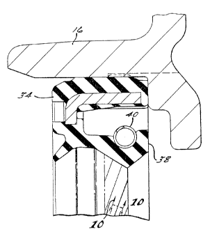
Referring now to FIGS. 7 and 8, a seal generally shown at
32 has an overall outer diameter slightly larger than the inner
diameter of the bore 12 shown in FIGS. 1 through 6. The seal 32
comprises an elastomeric annular base member 34, preferably
composed of a fluoroelastomer rubber material, molded about a
metallic annular shell or case 36 which contributes to the strength
and stiffnesC of the seal 32. It is preferred to provide (8 sets
of 3) nubs or anti-stick bumps (not shown) on the bottom or axial
inward surface of the base for packaging, so seals will not stick
together when roll packed', and notches 37 for mold locating pins (8
7
CA 02113878 2001-06-08
sets of 2) on the top or axial outward surface of the base for
controlling the location.c~f the metal shell or case 36 during the
molding proces:~. Depending from the base 34 is an annular sealing
member in the form of an annular arm 38 having therein a groove
for receiving an annular coil spring 40. The annular spring 40
provides a spring tensic~:r~ in a radially inward direction to
maintain the sealing surface 42 of the arm 38 in engagement with
the crankshaft or other cylindrical member entering the housing
through the port 12. Al:~o depending radially inwardly from the
arm 38 is a racLial lip 44 which :is more flexible than the sealing
surface 42 and which tends t:o prevent containments from entering
into the sealing surface def=fined at 42.
On the outer diamel~er of the base member 34 of the seal 32
are a pair of annular ribe 46 and 48. The rib 46 is a sealing rib
and the outer ~~iameter of the seal 32 at the rib 46 is slightly
greater than th.e inner diame ter of the bore at the sealing surface
26. Thus, the sealing rib 46 will be in compression when the seal
32 is installed within the bore 12 and provide sealing engagement
within the bore. As shown in FIG. 9, the locking or retention rib
48 is also of an outer diameter slightly greater than the inner
diameter of the sealing sLrface 26 of the bore 12 such that it can
be compressed to conform to the inner diameter of the sealing
surface 26 thrc>ugh instal=L<~tion. The seal 32 is inserted axially
inwardly until the axial inner end of the base member 34 abuts the
surface 22 of the tabs 14 and the retention or locking rib 48
engages the groove 30 as shown in FIG. 9. Once the locking rib 48
engages the groove 30, it will decompress to its original outer
diameter, which is greater than the inner diameter at the surface
26 and thereb~~ resist movement in an axial outward direction
through abutment of the axially outer edge of the ledge 52 of the
groove 30. This locking arrangement further resists relative
8
CA 02113878 2001-06-08
circumferentia_L motion between the seal 32 and the engine cover
10, opposing the frictional force generated by the turning of the
crankshaft. F,gain, the efficiency of the locking arrangement
allows a reduction of the seal width, reducing the weight and
material cost of the seal.
Referring now to FIG.. 10, the figure illustrates a preferred
configuration for the ra<~:ially inward sealing surface 42. The
sealing surface 42 ha:~ sE:ries of 63 ribs or ridges 50 of
approximately equal length, equally spaced around its
circumference, the ridges '~0 being arranged in right hand helical
or diagonal configuration so that they axially overlap. Should
any oil (or otr.er fluid u:>ed) seep between the surface 42 and the
crank shaft (or other cyiindrical object), the rotation of the
shaft will tend to move the oil :in a clockwise direction (looking
from the outer or air side of the engine cover 10, and the ridges
will channel the oil back: into the engine. Thus, there is a
~~pumping" action created by the rotation of the shaft. For
applications requiring opposite rotat:ion, the orientation of the
ridges 50 would be reversed.
FIGS. 11, 12 and :1.3 illustrate another embodiment of the
invention in which an annular lip or protrusion 102 is molded into
the inner diameter of the flange 16. All other aspects of the
invention remain the same-.. However, in this embodiment, the outer
diameter of the seal at the retaining rib 4B may be decreased
slightly to facilitate insertion since the protrusion provides a
greater lockincl force as :he surface of the ledge 52 (FIG. 4) is
increased by the addition of the protrusion 102. In this
embodiment, the outer
9
s~a.ameter of 'the rib 48 could actually be less than the inner
diameter of the sealing surface 26.
The protrusion 102 allows for the de-flashing of the
molded housing at the protrusion without cutting, scratching or
damaging in any way the seal area 26. The extra step of die de-
flashing eliminates any flash in the mold which may break off at
seal installation which would then be a contaminant and could lead
to seal failure. The die de-flashing process also allows for a
sharp edge at the protrusion tip at the surface 52 which improves
seal retention as opposed to an irregular or tapered edge.
Further, in the molding process, the edge of the mold
cavity parting line wears over time, resulting in the formation of
burrs. As the cavity opens the burrs will leave withdrawal marks,
which over time may become deep enough to create an oil leak path.
The protrusion 102 creates the smallest outer diameter for the bore
and thus the mold cavity parting line would occur at this point,
and the withdrawal marks would be located on the inner diameter of
the protrusion 102 which is not a critical seal area.
The present invention has been described in an
illustrative manner. It is to be understood that the terminology
which has been used is intended to be in the nature of words or
description rather than of limitation. Many modifications and
variations are possible in light of the above disclosure.
Therefore, within the scope of the attached claims, the present
invention may be practiced otherwise than as specifically
described.