Language selection

Search

Patent 2114099 Summary

Third-party information liability

Some of the information on this Web page has been provided by external sources. The Government of Canada is not responsible for the accuracy, reliability or currency of the information supplied by external sources. Users wishing to rely upon this information should consult directly with the source of the information. Content provided by external sources is not subject to official languages, privacy and accessibility requirements.

Claims and Abstract availability

Any discrepancies in the text and image of the Claims and Abstract are due to differing posting times. Text of the Claims and Abstract are posted:

  • At the time the application is open to public inspection;
  • At the time of issue of the patent (grant).
(12) Patent Application: (11) CA 2114099
(54) English Title: MITRE JOINTS IN WOOD FRAMES FOR DOORS AND THE LIKE
(54) French Title: ASSEMBLAGE A ONGLET D'OSSATURES DE PORTE ET ARTICLES ANALOGUES
Status: Deemed Abandoned and Beyond the Period of Reinstatement - Pending Response to Notice of Disregarded Communication
Bibliographic Data
Abstracts

English Abstract


A mitre joint and a method and apparatus for its manufacture are disclosed
A joint between two workpieces has a hole extending through one of the workpieces and
into the other, across the line of juncture of the two workpieces, and preferably
perpendicular to the line of juncture. A screw is driven into the hole to join the
workpieces. A dowel is then inserted into the hole behind the screw and is then trimmed
to provide a flush edge surface on the workpiece. The manufacture of the joint lends itself
to automation and eliminates the clamping and setting time required with a convention
glued and doweled joint.


Claims

Note: Claims are shown in the official language in which they were submitted.

-6-
CLAIMS:
1. A method of producing a mitre joint in which two elongate workpieces are
joined end to end at an angle along a line of juncture that bisects the angle between the two
workrpieces, said method comprising:
arranging the workpieces end to end at said angle;
drilling a hole through one workpiece and into the other, across the
line of juncture;
driving a screw into said hole to join the two workpieces;
inserting a dowel into said hole behind the screw; and
trimming the dowel.
2. A method according to Claim 1 including applying adhesive to at least one
of the end faces before arranging the workpieces end to end.
3. A method of joining two workpieces at a predetermined angle with a mitre
joint having a line of juncture that bisects the predetermined angle, said method
comprising
securing the workpieces on a moving support to with the workpieces
arranged end to end at the predetermined angle;
advancing the workpieces and the support to a first station;
driving a drill at the first station to form a hole through one of the
workpieces and into the other of the workpieces, across the line of juncture;
advancing the support to a second station;
inserting a screw at the second station into the hole;
operating a screwdriver at the second station to drive the screw into
the hole to join the two workpieces;

-7-
advancing the sport to a third station;
inserting a dowel at the third station into the hole, behind the screw;
advancing the support to a fourth station; and
trimming the dowel at the fourth station.
4. A method according to Claim 3 including the preliminary step of applying
adhesive to at least one of the workpiece ends before arranging the workpieces end to end
on the support.
5. Apparatus for securing two workpieces together at an angle along a line of
juncture bisecting the angle, the apparatus comprising:
a support,
clamping means for clamping the workpieces on the support with the
workpieces arranged at said angle;
support advancing means for advancing the support sequentially to a
plurality of work stations;
a first work station comprising a drill and a means for driving the
drill against the workpieces to form a hole for one of the workpieces and into the other,
across the line of juncture;
a second work station comprising a screw insertion means for
inserting a screw into the hole and driving the screw into the hole to join the two
workpieces;
a third work station comprising dowel insertion means for inserting
the dowel into the hole, behind the screw; and
a fourth work station comprising dowel trimming means for
trimming the dowel.

-8-
6. Apparatus according to Claim 5 where the support means comprise a table
and a jig on the table for aligning the workpieces in a desired alignment.
7. Apparatus according to Claim 6 wherein the clamp means comprise an
overhead clamp mounted on the table.
8. Apparatus according to Claim 5 wherein the screw insertion means
comprises a screw magazine, a screw feeder for feeding screws one at a time from the
magazine, and a screw driver for receiving a screw from the screw driver and driving the
screw into the hole.
9. Apparatus according to Claim 5 wherein the dowel insertion means comprise
a dowel magazine for holding a plurality of dowels and a dowel feeder means for feeding
the dowels one at a time from the magazine and dowel insertion means for receiving a
dowel from the dowel feeder means and injecting the dowel into the hole.
10. Apparatus according to Claim 5 wherein the dowel trimming means
comprise a dowel cut-off saw and a sander.
11. A mitre joint comprising two workpieces arranged at an angle and abutting
end to end along a line of juncture bisecting the angle, a hole extending through one
workpiece and into the other, across the line of juncture, a screw in the hole, joining the
workpieces, the head of the screw being countersunk and a dowel in the hole behind the
screw.
12. A joint according to Claim 11 where the dowel has an outer face flush with
the surrounding outer face of the said one workpiece.
13. A mitre joint according to Claim 11 including adhesive joining the
workpieces along the line of juncture.
14. A mitre joint according to Claim 11, 12 or 13 wherein the screw is

-9-
perpendicular to the line of juncture.
15. A frame comprising four workpieces joined at four corners, each corner
being a mitre joint comprising a line of juncture between a respective pair of the
workpieces, and including a hole extending through one workpiece and into the other,
across the line of juncture, a screw in the hole, joining the workpieces, with the head of
the screw countersunk, and a dowel in the hole behind the screw.
16. A frame according to Claim 15 wherein the screw is perpendicular to the
line of juncture.
17. A cupboard door comprising a panel and a plurality of frame members
surrounding the panel, the frame members being joined by mitre joints, each of which
comprises two frame members arranged at an angle and abutting end to end along a line of
juncture bisecting the angle, a hole extending through one frame member and into the
other, across the line of juncture, a screw in the hole, joining the frame members, the head
of the screw being countersunk and a dowel in the hole behind the screw.

Description

Note: Descriptions are shown in the official language in which they were submitted.


21140~9
Ml~RE JOINTS IN WOOD ~Al~ S FOR DOORS AND THE LIKE
The present invention relates to the joining of wood and more particularly to
mitre joints and their pro~uction
Mitre joints are commonly used in frames, for ~...p'e in the frames of
panel doors for cab~ets and the like. These joints are formed by cutting the workpiece
ends to mate along a line of junclule that bisects the angle b~wæn the workpieces, usuaUy
equally. The workpi~Pces are joined with adhesive and dowels or splines set into the
workI)ie~es to bridge the line of juncture. This conventional glued and doweled joint is
subject to loosening and parting owing to changes in humidity and te~ erature. It is
difficult to make, and the joint must be clamped until the glue is fully set. The prior art
joint does not lend itself to high speed or ~u~~ ed pro~ucti-n.
The present invention relates to novel mitre joints that mitig~t~P these
problems and to me~ho~ls and appa~alus for their m~nllfact~lre.
According to one aspect of the present invention there is provided a mitre
joint comprising t-wo workpieces allanged at an angle and abutting end to end along a line
of juncture bi.~ecting the angle, a hole eY~Pnding through one wo.~:ece and into the other,
across the line of junclu~, a screw in the hole, joining the wolk~ieePs, the head of the
screw being count~ lk and a dowel in the hole behind the screw.
The screw extends across the joint and forms a strong coupling that wiU not
be disturbed by imm~ te h~n-lling after the joint is made or, in the long term, by changes
in hllmi~ity and te,npe.ature. The dowel plug conceals the screw f~tenPr and is itself
hardly noticeable as the end of the dowel is trimm~ flush with the edge of the workpiece.
According to another aspect of the present invention there is provided a
method of pro~ucing a mitre joint in which two elongate workpieces are joined end to end

~- 211~Q9~
at an angle along a line of juncture that bisects the angle between the two workpieces, said
method compri~in-:
all~nging the workri~s end to end at said angle;
drilling a hole through one workp:~ce and into the other, across the
line of juncture;
driving a screw into said hole to join the two workpieces;
inserting a dowel into said hole behind the screw; and
!.;----nin_ the dowel.
This method lends itself to aulol"ated production.
In a prer~lr~d embodiment of the method there is provided a method of
joining two wc 1~ r~s at a plcclete~ in~ angle with a mitre joint having a line of
juncture that bisects the p~ete-~ ed angle, said method compri~ing:
s~u-;nP the workri.ooes on a moving support with the workpieces
arranged end to end at the predetermin~ angle;
advancing the workpieces and the support to a first station;
driving a drill at the first station to form a hole through one of the
workpi~s and into the other of the Wol~ cces, across the line of jur~tule;
a~lvancing the support to a second station;
in~l ling a screw at the second station into the hole;
o~e,aling a scr~wd~ er at the second station to drive the screw into
the hole to join the two workpieces;
advancing the support to a third station;
ins~lling a dowel at the third station into the hole, behind the screw;
advancing the support to a fourth station; and

21i40Y9
;ng the dowel at the fourth station.
According to a further aspect of the present invention there is provided
a~palalus for ~ECU.;i~g two workpieces together at an angle along a line of jwl~lu
bi~ting the angle, the appala~us comprising:
a s~lppoll,
c1zn.pinP means for cl~llpillg the wu.kl icces on the support with the
workpieces a~l~ ged at said angle;
support advancing means for advancing the support sequentially to a
plurality of work st~tions;
a first work station comprising a drill and a means for driving the
drill against the workpi~s to form a hole through one of the workpieces and into the
other, across the line of jùn~;tu~
a second work station compri~ing a screw insertion means for
inserting a screw into the hole and driving the screw into the hole to join the two
workpi~es;
a third work station comprising dowel insertion means for inserting
the dowel into the hole, behind the screw; and
a fourth work station comprising dowel trimming means for
l.;n~...;ng the dowel.
In the accolnpall~,ng drawings, which ilhl~tr~e an exemplary embodiment
of the present ihlvell~ion:
Figure 1 ;11IJS~ eS a frame constructed according to the present
invention;
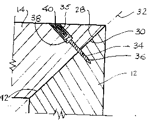
Figure 2 is a cross sec~ion of one corner of the frame;

- 211~0~9
Figure 3 is a s~h~ l;c view of an app~dlus for manuf~tlJring the
frame.
Referri~ to the accGll,panyilg drawings, Figure 1 illustrates a p~n~1~d
cu~o~d door 6. The door has a frame 8 composed of four edge members 10, 12, 14 and
16, and a centre panel 18. The side memhP,rs meet at mitred corners 20, 22, 24 and 26.
The four mitred corners are all the same so that only one will be described in detail in the
following.
Figure 2 is a cross-section of the corner 20 between the members 12 and 14.
The ends 28 and 30 of the ...e~..he ~ 12 and 14 are cut off at angles so as to meet along a
line of juncture 32 that bisects the right angle between the two members. A hole 34
eYtends through the ..~el,lber 12 and into the m~,mber 14, perpendicular to and across the
line of junc;lu~ 32. The outer end 35 of the hole is co~ '*~u~-k. A screw 36 is driven
into the hole to join the two frame ..~..be~s. The screw head 38 is set into thecounte,~unk outer end 35 of the hole 34. A dowel 40 is inserted in the hole behind the
screw head 38 and is tnmm~ flush with the edge of the ...~..be~ 12. In this embo~imPnt,
before assembly a layer of adhesive 42 is applied to one or both of the end faces 28 and 30
of the two m~mbers. This serves not only to allpm~nt the strength of the joint but also to
fill any irregu1~riti~s between the ends of the two pieces.
An app~tus for the aulG-~atic production of a joint of this sort is ill~lsl~t~
in Figure 3. As ill~lstr~t~ in that drawing, the ~pp~ 44 inc~ll)des a support table 46
cal,,~ ing a jig in the form of a fence 48 for ~ligning the workI-:^c~-s, A hold down clamp
50 is mounted on the table and clamps the two workpieces 12 and 14 onto the table.
The support table is advanced stepwise past a sequence of work stations to
form the joint. The first station is a drilling station 52 where a drill 54 drives a drill bit 56

211~09g
- s -
into the edge of the workpi~e 12, and through the workpiece 12 into the workpiece 14 t~
form the hole 34 with its count~ Jnk outer end 35. The second station is a Scl~;Wing
station 58 where a supply of screws is held in a mag~7ine 60. A screw feeder 62 delivers
screws one by one from the m~7.ine to a screw driver 64 that drives the screws into the
hole 34 to join the two workpieces.
The third work station is a dowel insertion station 66 which has a dowel
m~7ine 68 holding a supply of dowels. A dowel feeder 70 delivers the dowels one by
one from the dowel ma~7ine to a dowel insertion gun 72. The insertion gun drives a
dowel into the hole 34 behind the screw.
The final work station is a trimming station 74 that int ludes a cut-off saw 76
for cutting off the end of the dowel 40 projecting from the edge face of the workpiece 12
and sander 78 for s~ndin~ the end of a dowel to a smooth, finiched surface flush with the
edge of the wolhl):ece 12.
Wo ~ cc~s leaving this au~"~ated apl)~atus may be h~n-llPd i,.""ff~ ~y
without waiting for the setting or the curing of adhesive.
While one embo~iment of the invention has been described in the foregoil~g,
the invention is not limited to that embo~iment Other embodimPnts are possible and are
inten~ to be included within the scope of this applit~til n. The invention should be
construed as limited solely by the scope of the appended claims.

Representative Drawing
A single figure which represents the drawing illustrating the invention.
Administrative Status

2024-08-01:As part of the Next Generation Patents (NGP) transition, the Canadian Patents Database (CPD) now contains a more detailed Event History, which replicates the Event Log of our new back-office solution.

Please note that "Inactive:" events refers to events no longer in use in our new back-office solution.

For a clearer understanding of the status of the application/patent presented on this page, the site Disclaimer , as well as the definitions for Patent , Event History , Maintenance Fee  and Payment History  should be consulted.

Event History

Description Date
Deemed Abandoned - Failure to Respond to Maintenance Fee Notice 2002-01-24
Inactive: Dead - RFE never made 2002-01-24
Application Not Reinstated by Deadline 2002-01-24
Inactive: Abandon-RFE+Late fee unpaid-Correspondence sent 2001-01-24
Application Published (Open to Public Inspection) 1995-07-25

Abandonment History

Abandonment Date Reason Reinstatement Date
2002-01-24

Maintenance Fee

The last payment was received on 2000-12-20

Note : If the full payment has not been received on or before the date indicated, a further fee may be required which may be one of the following

  • the reinstatement fee;
  • the late payment fee; or
  • additional fee to reverse deemed expiry.

Patent fees are adjusted on the 1st of January every year. The amounts above are the current amounts if received by December 31 of the current year.
Please refer to the CIPO Patent Fees web page to see all current fee amounts.

Fee History

Fee Type Anniversary Year Due Date Paid Date
MF (application, 4th anniv.) - small 04 1998-01-26 1998-01-16
MF (application, 5th anniv.) - small 05 1999-01-25 1999-01-15
MF (application, 6th anniv.) - small 06 2000-01-24 2000-01-21
MF (application, 7th anniv.) - small 07 2001-01-24 2000-12-20
Owners on Record

Note: Records showing the ownership history in alphabetical order.

Current Owners on Record
ELIAS WOODWORK AND MANUFACTURE LTD.
Past Owners on Record
D. RALPH FEHR
Past Owners that do not appear in the "Owners on Record" listing will appear in other documentation within the application.
Documents

To view selected files, please enter reCAPTCHA code :


To view images, click a link in the Document Description column. To download the documents, select one or more checkboxes in the first column and then click the "Download Selected in PDF format (Zip Archive)" or the "Download Selected as Single PDF" button.

List of published and non-published patent-specific documents on the CPD .

If you have any difficulty accessing content, you can call the Client Service Centre at 1-866-997-1936 or send them an e-mail at CIPO Client Service Centre.


Document
Description 
Date
(yyyy-mm-dd) 
Number of pages   Size of Image (KB) 
Drawings 1995-07-24 2 40
Description 1995-07-24 5 187
Abstract 1995-07-24 1 19
Claims 1995-07-24 2 40
Claims 1995-07-24 4 129
Representative drawing 1998-05-27 1 9
Reminder - Request for Examination 2000-09-25 1 116
Courtesy - Abandonment Letter (Request for Examination) 2001-03-06 1 169
Courtesy - Abandonment Letter (Maintenance Fee) 2002-02-20 1 182
Fees 1996-11-18 1 47
Fees 1996-01-16 1 35
PCT Correspondence 1995-04-06 2 59
PCT Correspondence 1994-09-29 1 26
PCT Correspondence 1994-05-02 1 24
Courtesy - Office Letter 1995-03-23 1 23
Courtesy - Office Letter 1995-06-04 1 13