Sélection de la langue

Search

Sommaire du brevet 2114099 

Énoncé de désistement de responsabilité concernant l'information provenant de tiers

Une partie des informations de ce site Web a été fournie par des sources externes. Le gouvernement du Canada n'assume aucune responsabilité concernant la précision, l'actualité ou la fiabilité des informations fournies par les sources externes. Les utilisateurs qui désirent employer cette information devraient consulter directement la source des informations. Le contenu fourni par les sources externes n'est pas assujetti aux exigences sur les langues officielles, la protection des renseignements personnels et l'accessibilité.

Disponibilité de l'Abrégé et des Revendications

L'apparition de différences dans le texte et l'image des Revendications et de l'Abrégé dépend du moment auquel le document est publié. Les textes des Revendications et de l'Abrégé sont affichés :

  • lorsque la demande peut être examinée par le public;
  • lorsque le brevet est émis (délivrance).
(12) Demande de brevet: (11) CA 2114099
(54) Titre français: ASSEMBLAGE A ONGLET D'OSSATURES DE PORTE ET ARTICLES ANALOGUES
(54) Titre anglais: MITRE JOINTS IN WOOD FRAMES FOR DOORS AND THE LIKE
Statut: Réputée abandonnée et au-delà du délai pour le rétablissement - en attente de la réponse à l’avis de communication rejetée
Données bibliographiques
Abrégés

Abrégé anglais


A mitre joint and a method and apparatus for its manufacture are disclosed
A joint between two workpieces has a hole extending through one of the workpieces and
into the other, across the line of juncture of the two workpieces, and preferably
perpendicular to the line of juncture. A screw is driven into the hole to join the
workpieces. A dowel is then inserted into the hole behind the screw and is then trimmed
to provide a flush edge surface on the workpiece. The manufacture of the joint lends itself
to automation and eliminates the clamping and setting time required with a convention
glued and doweled joint.

Revendications

Note : Les revendications sont présentées dans la langue officielle dans laquelle elles ont été soumises.


-6-
CLAIMS:
1. A method of producing a mitre joint in which two elongate workpieces are
joined end to end at an angle along a line of juncture that bisects the angle between the two
workrpieces, said method comprising:
arranging the workpieces end to end at said angle;
drilling a hole through one workpiece and into the other, across the
line of juncture;
driving a screw into said hole to join the two workpieces;
inserting a dowel into said hole behind the screw; and
trimming the dowel.
2. A method according to Claim 1 including applying adhesive to at least one
of the end faces before arranging the workpieces end to end.
3. A method of joining two workpieces at a predetermined angle with a mitre
joint having a line of juncture that bisects the predetermined angle, said method
comprising
securing the workpieces on a moving support to with the workpieces
arranged end to end at the predetermined angle;
advancing the workpieces and the support to a first station;
driving a drill at the first station to form a hole through one of the
workpieces and into the other of the workpieces, across the line of juncture;
advancing the support to a second station;
inserting a screw at the second station into the hole;
operating a screwdriver at the second station to drive the screw into
the hole to join the two workpieces;

-7-
advancing the sport to a third station;
inserting a dowel at the third station into the hole, behind the screw;
advancing the support to a fourth station; and
trimming the dowel at the fourth station.
4. A method according to Claim 3 including the preliminary step of applying
adhesive to at least one of the workpiece ends before arranging the workpieces end to end
on the support.
5. Apparatus for securing two workpieces together at an angle along a line of
juncture bisecting the angle, the apparatus comprising:
a support,
clamping means for clamping the workpieces on the support with the
workpieces arranged at said angle;
support advancing means for advancing the support sequentially to a
plurality of work stations;
a first work station comprising a drill and a means for driving the
drill against the workpieces to form a hole for one of the workpieces and into the other,
across the line of juncture;
a second work station comprising a screw insertion means for
inserting a screw into the hole and driving the screw into the hole to join the two
workpieces;
a third work station comprising dowel insertion means for inserting
the dowel into the hole, behind the screw; and
a fourth work station comprising dowel trimming means for
trimming the dowel.

-8-
6. Apparatus according to Claim 5 where the support means comprise a table
and a jig on the table for aligning the workpieces in a desired alignment.
7. Apparatus according to Claim 6 wherein the clamp means comprise an
overhead clamp mounted on the table.
8. Apparatus according to Claim 5 wherein the screw insertion means
comprises a screw magazine, a screw feeder for feeding screws one at a time from the
magazine, and a screw driver for receiving a screw from the screw driver and driving the
screw into the hole.
9. Apparatus according to Claim 5 wherein the dowel insertion means comprise
a dowel magazine for holding a plurality of dowels and a dowel feeder means for feeding
the dowels one at a time from the magazine and dowel insertion means for receiving a
dowel from the dowel feeder means and injecting the dowel into the hole.
10. Apparatus according to Claim 5 wherein the dowel trimming means
comprise a dowel cut-off saw and a sander.
11. A mitre joint comprising two workpieces arranged at an angle and abutting
end to end along a line of juncture bisecting the angle, a hole extending through one
workpiece and into the other, across the line of juncture, a screw in the hole, joining the
workpieces, the head of the screw being countersunk and a dowel in the hole behind the
screw.
12. A joint according to Claim 11 where the dowel has an outer face flush with
the surrounding outer face of the said one workpiece.
13. A mitre joint according to Claim 11 including adhesive joining the
workpieces along the line of juncture.
14. A mitre joint according to Claim 11, 12 or 13 wherein the screw is

-9-
perpendicular to the line of juncture.
15. A frame comprising four workpieces joined at four corners, each corner
being a mitre joint comprising a line of juncture between a respective pair of the
workpieces, and including a hole extending through one workpiece and into the other,
across the line of juncture, a screw in the hole, joining the workpieces, with the head of
the screw countersunk, and a dowel in the hole behind the screw.
16. A frame according to Claim 15 wherein the screw is perpendicular to the
line of juncture.
17. A cupboard door comprising a panel and a plurality of frame members
surrounding the panel, the frame members being joined by mitre joints, each of which
comprises two frame members arranged at an angle and abutting end to end along a line of
juncture bisecting the angle, a hole extending through one frame member and into the
other, across the line of juncture, a screw in the hole, joining the frame members, the head
of the screw being countersunk and a dowel in the hole behind the screw.

Description

Note : Les descriptions sont présentées dans la langue officielle dans laquelle elles ont été soumises.

21140~9
Ml~RE JOINTS IN WOOD ~Al~ S FOR DOORS AND THE LIKE
The present invention relates to the joining of wood and more particularly to
mitre joints and their pro~uction
Mitre joints are commonly used in frames, for ~...p'e in the frames of
panel doors for cab~ets and the like. These joints are formed by cutting the workpiece
ends to mate along a line of junclule that bisects the angle b~wæn the workpieces, usuaUy
equally. The workpi~Pces are joined with adhesive and dowels or splines set into the
workI)ie~es to bridge the line of juncture. This conventional glued and doweled joint is
subject to loosening and parting owing to changes in humidity and te~ erature. It is
difficult to make, and the joint must be clamped until the glue is fully set. The prior art
joint does not lend itself to high speed or ~u~~ ed pro~ucti-n.
The present invention relates to novel mitre joints that mitig~t~P these
problems and to me~ho~ls and appa~alus for their m~nllfact~lre.
According to one aspect of the present invention there is provided a mitre
joint comprising t-wo workpieces allanged at an angle and abutting end to end along a line
of juncture bi.~ecting the angle, a hole eY~Pnding through one wo.~:ece and into the other,
across the line of junclu~, a screw in the hole, joining the wolk~ieePs, the head of the
screw being count~ lk and a dowel in the hole behind the screw.
The screw extends across the joint and forms a strong coupling that wiU not
be disturbed by imm~ te h~n-lling after the joint is made or, in the long term, by changes
in hllmi~ity and te,npe.ature. The dowel plug conceals the screw f~tenPr and is itself
hardly noticeable as the end of the dowel is trimm~ flush with the edge of the workpiece.
According to another aspect of the present invention there is provided a
method of pro~ucing a mitre joint in which two elongate workpieces are joined end to end

~- 211~Q9~
at an angle along a line of juncture that bisects the angle between the two workpieces, said
method compri~in-:
all~nging the workri~s end to end at said angle;
drilling a hole through one workp:~ce and into the other, across the
line of juncture;
driving a screw into said hole to join the two workpieces;
inserting a dowel into said hole behind the screw; and
!.;----nin_ the dowel.
This method lends itself to aulol"ated production.
In a prer~lr~d embodiment of the method there is provided a method of
joining two wc 1~ r~s at a plcclete~ in~ angle with a mitre joint having a line of
juncture that bisects the p~ete-~ ed angle, said method compri~ing:
s~u-;nP the workri.ooes on a moving support with the workpieces
arranged end to end at the predetermin~ angle;
advancing the workpieces and the support to a first station;
driving a drill at the first station to form a hole through one of the
workpi~s and into the other of the Wol~ cces, across the line of jur~tule;
a~lvancing the support to a second station;
in~l ling a screw at the second station into the hole;
o~e,aling a scr~wd~ er at the second station to drive the screw into
the hole to join the two workpieces;
advancing the support to a third station;
ins~lling a dowel at the third station into the hole, behind the screw;
advancing the support to a fourth station; and

21i40Y9
;ng the dowel at the fourth station.
According to a further aspect of the present invention there is provided
a~palalus for ~ECU.;i~g two workpieces together at an angle along a line of jwl~lu
bi~ting the angle, the appala~us comprising:
a s~lppoll,
c1zn.pinP means for cl~llpillg the wu.kl icces on the support with the
workpieces a~l~ ged at said angle;
support advancing means for advancing the support sequentially to a
plurality of work st~tions;
a first work station comprising a drill and a means for driving the
drill against the workpi~s to form a hole through one of the workpieces and into the
other, across the line of jùn~;tu~
a second work station compri~ing a screw insertion means for
inserting a screw into the hole and driving the screw into the hole to join the two
workpi~es;
a third work station comprising dowel insertion means for inserting
the dowel into the hole, behind the screw; and
a fourth work station comprising dowel trimming means for
l.;n~...;ng the dowel.
In the accolnpall~,ng drawings, which ilhl~tr~e an exemplary embodiment
of the present ihlvell~ion:
Figure 1 ;11IJS~ eS a frame constructed according to the present
invention;
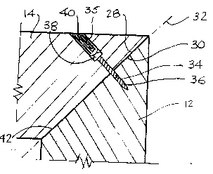
Figure 2 is a cross sec~ion of one corner of the frame;

- 211~0~9
Figure 3 is a s~h~ l;c view of an app~dlus for manuf~tlJring the
frame.
Referri~ to the accGll,panyilg drawings, Figure 1 illustrates a p~n~1~d
cu~o~d door 6. The door has a frame 8 composed of four edge members 10, 12, 14 and
16, and a centre panel 18. The side memhP,rs meet at mitred corners 20, 22, 24 and 26.
The four mitred corners are all the same so that only one will be described in detail in the
following.
Figure 2 is a cross-section of the corner 20 between the members 12 and 14.
The ends 28 and 30 of the ...e~..he ~ 12 and 14 are cut off at angles so as to meet along a
line of juncture 32 that bisects the right angle between the two members. A hole 34
eYtends through the ..~el,lber 12 and into the m~,mber 14, perpendicular to and across the
line of junc;lu~ 32. The outer end 35 of the hole is co~ '*~u~-k. A screw 36 is driven
into the hole to join the two frame ..~..be~s. The screw head 38 is set into thecounte,~unk outer end 35 of the hole 34. A dowel 40 is inserted in the hole behind the
screw head 38 and is tnmm~ flush with the edge of the ...~..be~ 12. In this embo~imPnt,
before assembly a layer of adhesive 42 is applied to one or both of the end faces 28 and 30
of the two m~mbers. This serves not only to allpm~nt the strength of the joint but also to
fill any irregu1~riti~s between the ends of the two pieces.
An app~tus for the aulG-~atic production of a joint of this sort is ill~lsl~t~
in Figure 3. As ill~lstr~t~ in that drawing, the ~pp~ 44 inc~ll)des a support table 46
cal,,~ ing a jig in the form of a fence 48 for ~ligning the workI-:^c~-s, A hold down clamp
50 is mounted on the table and clamps the two workpieces 12 and 14 onto the table.
The support table is advanced stepwise past a sequence of work stations to
form the joint. The first station is a drilling station 52 where a drill 54 drives a drill bit 56

211~09g
- s -
into the edge of the workpi~e 12, and through the workpiece 12 into the workpiece 14 t~
form the hole 34 with its count~ Jnk outer end 35. The second station is a Scl~;Wing
station 58 where a supply of screws is held in a mag~7ine 60. A screw feeder 62 delivers
screws one by one from the m~7.ine to a screw driver 64 that drives the screws into the
hole 34 to join the two workpieces.
The third work station is a dowel insertion station 66 which has a dowel
m~7ine 68 holding a supply of dowels. A dowel feeder 70 delivers the dowels one by
one from the dowel ma~7ine to a dowel insertion gun 72. The insertion gun drives a
dowel into the hole 34 behind the screw.
The final work station is a trimming station 74 that int ludes a cut-off saw 76
for cutting off the end of the dowel 40 projecting from the edge face of the workpiece 12
and sander 78 for s~ndin~ the end of a dowel to a smooth, finiched surface flush with the
edge of the wolhl):ece 12.
Wo ~ cc~s leaving this au~"~ated apl)~atus may be h~n-llPd i,.""ff~ ~y
without waiting for the setting or the curing of adhesive.
While one embo~iment of the invention has been described in the foregoil~g,
the invention is not limited to that embo~iment Other embodimPnts are possible and are
inten~ to be included within the scope of this applit~til n. The invention should be
construed as limited solely by the scope of the appended claims.

Dessin représentatif
Une figure unique qui représente un dessin illustrant l'invention.
États administratifs

2024-08-01 : Dans le cadre de la transition vers les Brevets de nouvelle génération (BNG), la base de données sur les brevets canadiens (BDBC) contient désormais un Historique d'événement plus détaillé, qui reproduit le Journal des événements de notre nouvelle solution interne.

Veuillez noter que les événements débutant par « Inactive : » se réfèrent à des événements qui ne sont plus utilisés dans notre nouvelle solution interne.

Pour une meilleure compréhension de l'état de la demande ou brevet qui figure sur cette page, la rubrique Mise en garde , et les descriptions de Brevet , Historique d'événement , Taxes périodiques et Historique des paiements devraient être consultées.

Historique d'événement

Description Date
Réputée abandonnée - omission de répondre à un avis sur les taxes pour le maintien en état 2002-01-24
Inactive : Morte - RE jamais faite 2002-01-24
Demande non rétablie avant l'échéance 2002-01-24
Inactive : Abandon.-RE+surtaxe impayées-Corr envoyée 2001-01-24
Demande publiée (accessible au public) 1995-07-25

Historique d'abandonnement

Date d'abandonnement Raison Date de rétablissement
2002-01-24

Taxes périodiques

Le dernier paiement a été reçu le 2000-12-20

Avis : Si le paiement en totalité n'a pas été reçu au plus tard à la date indiquée, une taxe supplémentaire peut être imposée, soit une des taxes suivantes :

  • taxe de rétablissement ;
  • taxe pour paiement en souffrance ; ou
  • taxe additionnelle pour le renversement d'une péremption réputée.

Les taxes sur les brevets sont ajustées au 1er janvier de chaque année. Les montants ci-dessus sont les montants actuels s'ils sont reçus au plus tard le 31 décembre de l'année en cours.
Veuillez vous référer à la page web des taxes sur les brevets de l'OPIC pour voir tous les montants actuels des taxes.

Historique des taxes

Type de taxes Anniversaire Échéance Date payée
TM (demande, 4e anniv.) - petite 04 1998-01-26 1998-01-16
TM (demande, 5e anniv.) - petite 05 1999-01-25 1999-01-15
TM (demande, 6e anniv.) - petite 06 2000-01-24 2000-01-21
TM (demande, 7e anniv.) - petite 07 2001-01-24 2000-12-20
Titulaires au dossier

Les titulaires actuels et antérieures au dossier sont affichés en ordre alphabétique.

Titulaires actuels au dossier
ELIAS WOODWORK AND MANUFACTURE LTD.
Titulaires antérieures au dossier
D. RALPH FEHR
Les propriétaires antérieurs qui ne figurent pas dans la liste des « Propriétaires au dossier » apparaîtront dans d'autres documents au dossier.
Documents

Pour visionner les fichiers sélectionnés, entrer le code reCAPTCHA :


Pour visualiser une image, cliquer sur un lien dans la colonne description du document. Pour télécharger l'image (les images), cliquer l'une ou plusieurs cases à cocher dans la première colonne et ensuite cliquer sur le bouton "Télécharger sélection en format PDF (archive Zip)" ou le bouton "Télécharger sélection (en un fichier PDF fusionné)".

Liste des documents de brevet publiés et non publiés sur la BDBC .

Si vous avez des difficultés à accéder au contenu, veuillez communiquer avec le Centre de services à la clientèle au 1-866-997-1936, ou envoyer un courriel au Centre de service à la clientèle de l'OPIC.


Description du
Document 
Date
(aaaa-mm-jj) 
Nombre de pages   Taille de l'image (Ko) 
Dessins 1995-07-24 2 40
Description 1995-07-24 5 187
Abrégé 1995-07-24 1 19
Revendications 1995-07-24 2 40
Revendications 1995-07-24 4 129
Dessin représentatif 1998-05-27 1 9
Rappel - requête d'examen 2000-09-25 1 116
Courtoisie - Lettre d'abandon (requête d'examen) 2001-03-06 1 169
Courtoisie - Lettre d'abandon (taxe de maintien en état) 2002-02-20 1 182
Taxes 1996-11-18 1 47
Taxes 1996-01-16 1 35
Correspondance reliée au PCT 1995-04-06 2 59
Correspondance reliée au PCT 1994-09-29 1 26
Correspondance reliée au PCT 1994-05-02 1 24
Courtoisie - Lettre du bureau 1995-03-23 1 23
Courtoisie - Lettre du bureau 1995-06-04 1 13