Note: Descriptions are shown in the official language in which they were submitted.
WO 93!03668 PC°I'/US9~/06991
1
CAgtI~IAC OUTPUT .'ROBE ASSEMBLY
Field.of the Invention
The invention relates to cardiac output devices, and, in
particular, to devices which measure and monitor cardiac
output following open heart surgery.
Backciround -of the Tnvention
Cardiac probes are commonly used to measure and/or
monitor cardiac output, blood f~,ow, and stroke volume.
Typically the probes include an ultrasonic transducer which
is inserted into the heart via a, catheter or is attached to
the exterior of the heart. The transducer is coupled to an
external circuit which applies a high frequency electrical
!signal that causes the transducer to transmit ultrasonic
energy through a vessel in the heart. The energy reflected
25 in the vessel is then received by the transducer and sent
to the external circuitry for analysis and quantification.
These types of cardiac output probes are often attached
outside the pulmonary artery immediately following open
heart surgery to measure and monitor cardiac output. Since
2Q the probe is ' connected to external circuitry and
instrumentatian, the chest is typically left open during
the monitoring procedure, hereby restricting the time
period after completion of the surgery during which these
measurements can be made.
Summary of the ~xwention
The preferred embodiment of the present invention
comprises a cardiac output probe assembly which may be used
to measure and monitor cardiac- output during the post-
operative recovery period following open heart surgery.
30 The assembly comprises an elongated flexible chest tube
.having a proximal end which is inserted into the thoracic
cavity of a patient~ The tube;includes a main lumen for
draining fluids from the thoracic cavity and a secondary
lumen which carrzes leads attached to a cardiac output
~Y4? 93/03Gf~8 PCI'/US92/06991
2
probe. The probe is fastened to the pulmonary artery or
aorta vessel with detachable tines and/or sutures and
connected to appropriate monitoring devices to measure and
monitor cardiac output.'~~
When the desired measurements have been obtained, the
probe is removed by applying a pulling force to the probe
leads which releases the tines from connection with the
vessel. The leads are further withdrawn from the tube to
retract the probe within the chest tube where it housed
~.0 until the chest tube is removed from the thoracic cavity.
The distal end of the tube includes a mouth portion arid
a semicircular shield portion. The main lumen terminates
..at the mouth portion and the secondary lumen terminates
closely adjacent to the mouth portion such that the
withdrawal of the probe is not impeded by the distal end of
the tube. The distal end may also be generally circular
wherein the termination point of tie secondary lumen is
displaced to enable the probe to be housed within the main
lumen when fully retracted into the tube.
A mufti-lumen tube accommodates several cardiac output
devices and consolidates access to the thoracic cavity.
The tube comprises a main lumen for draining fluids prom
the thoracic cavity and a plurality of secondary lumens
which carry the leads for the cardiac output devices.
In accordance with a broader aspect of the present
invent~.on a medical device comprises a temporary implant
comprising an attachment portion which detachably fastens
the implant to tissue within a living body. A line is
connected to the implant wherein the attachment portion is
configured to cause release of the implant in response to
a force on the Zine. Tire device further comprises a tube
having a generally smooth outer surface to permit the tube
to be withdrawn from,tiss~ae of the living body by pulling
thereon. The tube is sized to permit the line to pass
therethrough and has a mouth portion which receives the
W~ 93!03668 PCT/1.1S92/06991
3
implant. The tube may comprise a wound drain and may have
drain holes proximal to one end thereof. The implant may
comprise a sensor, and the sensor may comprise a transducer
which produces electrical signals. The line may comprise
a wire for carrying electrical signals. The tube may have
two lumens, one of which is substantially larger than the
other, and the line may be disposed in the smaller of the
two lumens. The smaller of the two lumens imay terminate at
a location spaced from the mouth portion.
The mouth portion may be sized to permit the implant to
f it therein. The mouth portioWmay be formed by a shield
portion of subs~tant~.ally semicircular cross section
disposed on one side of the tube. The tube may comprise
two lumens, one being substantially smaller than the other,
the smaller of the two lumens being disposed on the same
side of the tube as the shield portion. The tube may be
flexible: The smaller of the lumens may have a slit
therein extending from a proximal end of the tube through
only a selected portion of the tube ~o perm~.t the line to
be removed from the lumen so that the tube can be cut to
proper size without cutting the line. The implant may
additionally comprise a body portion and that attachment
portion may comprise at least one tine attached to the body
portion. A distal end portion of the tine is spaced from
a surface of said body portion to permit ~,he distal end to
be inserted into tissue such that the tissue is between the
tine and the surface of the body portion. The tine may
extend in a direction generally parallel to the, surface of
the' body portion, wherein the tins is resilient so as to
forcibly bias the tissue between the tine and the surface
of the body! portion against 'the surface of the body
porti~n. The tine may have a proximal end portion which is
attached to the body portion and whichextends outwardly
from the surfaco of the body por~iora. The tine may have a
curved intermediate portion between the proximal end
CA 02114113 2003-O1-03
4
portion and the distal end portion. The transducing head
may also include an eyelet or notch to provide suture tie
areas for suturing the probe to the tissue with
dissolving sutures.
A method of removing a temporary implant detachably
attached to tissue within a living body comprises
applying force to a line which is connected to the
implant, utilizing the force to detach the implant from
the tissue, and utilizing the force to draw the implant
to a mouth portion of a tube disposed with the living
body, and withdrawing the tube from the living body. The
step of withdrawing may comprise retaining the implant at
the mouth of the tube during the withdrawing . The mouth
portion may open laterally to one side of the tube, and
the method may additionally comprise guiding the line
along a path disposed on the opposite side of the tube.
The step of guiding the line may comprise passing the
line through a lumen having a distal end spaced from the
mouth portion. The method may additionally comprise the
2U step of draining bodily fluids through the tube.
The present invention also provides a method of
performing a surgical procedure so that an attached
implant may be readily removed without further surgery
comprising attaching a temporary implant to tissue within
a living body and placing a tube in the living body such
that a distal end of the tube is in general proximity to
the implant, a proximal end of the tube extend out of the
living body, a line attached to the implant passes
through a lumen of the tube, and a portion of the line
and a portion of the tube are accessible from outside the
living body.
According to one aspect of the invention, there is
provided a medical device for use on extravascular tissue
CA 02114113 2003-09-11
4a
within a living body, comprising:
a temporary implant comprising an attachment portion
which is adapted to detachably fasten said implant to the
extravascular tissue;
a line, connected to said implant, said attachment
portion being configured to cause release of said implant
in response to a force on said line; and
a chest tube having a generally smooth outer surface
to permit said chest tube to be inserted into and
enclosed within the thoracic cavity of the living body
and to be withdrawn from the living body by pulling
thereon, said tube sized to permit said line to pass
therethrough and having a mouth portion which receives
said implant prior to withdrawal of said chest tube from
the thoracic cavity.
According to another aspect of the invention, there
is provided a medical device for use on extravascular
tissue within a living body, comprising:
a temporary implantable cardiac output probe
comprising an attachment portion which is adapted to
detachably fasten said implantable probe to the
extravascular tissue;
a line, connected to said implantable probe, said
attachment portion being configured to cause release of
said implant in response to a force on said line; and
a chest tube having a generally smooth outer surface
to permit said chest tube to be inserted into and
enclosed within the thoracic cavity of the living body
and to be withdrawn from the living body by pulling
thereon, said tube sized to permit said line to pass
therethrough and having a mouth portion which receives
said implant prior to withdrawal of said chest tube from
the thoracic cavity.
CA 02114113 2003-09-11
4b
According to another aspect of the invention, there
is provided the use of a chest tube disposed inside a
thoracic cavity of a living body to remove a temporary
implant detachably attached to tissue within said living
body, wherein the implant, having a line attached thereto
and extending through a lumen of said chest tube, is
drawn into a mouth portion of said chest tube by said
line; and withdrawing said chest tube containing said
temporary implant in said mouth portion, from said living
body.
According to a further aspect of the invention,
there is provided the use of a chest tube disposed inside
a living body to remove a temporary implant detachably
attached to tissue within said living body, wherein a
distal end of said chest tube is in general proximity to
said implant, a proximal end of said chest tube extends
out of the living body, a line attached to said implant
passes through a lumen of said chest tube, and a portion
of said line and a portion of said chest tube are
accessible from outside said living body.
Brief Description of the Drawings
Figure 1 is a perspective view of a cardiac output
probe assembly in accordance with the present invention;
WO 931U3~68 JPCT/US92/06991
s ~ a .z '~
Figure 2 is a partial cut-away view of the distal end of
the tube;
Figure 3 is an enlarged view of the transducing head of
the probe;
Figure 4 illustrates the probe attached to a vessel;
Figure 5 shows the probe retracted within the tube;
Figure 6 is a partial cut-away view of a tube having a
generally cylindrical distal end;
Figure 7 is a cross--sectional view of. a mufti-lumen
. 10 tube;
Figure 8 illustrates another embodiment of a transducing
head having a suture tie portion comprising an eyelet;
Figure 9 illustrates a further embodiment of a
transducing head having suture tie portions comprising
notches.
Detailed Description of the Invention
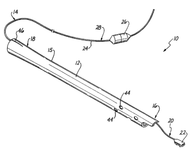
A cardiac output probe assembly 10 in accordance with
the present irwention is illustrated in Figure 1. The
assembly 20 compra.ses an elongated drair~ag~ tube 12 which
carries a cardiac output probe 14 therein. The tube 12 has
a generally smooth outer surface 25 and a preferred outside
diameter in the range of 28-40 French. The tube 12 is
preferably formed of a flexible biocompatible plastic such
as PVC and includes a ,distal end 16 which is adapte~t for
placement within the thoracic cavity of a living body and
a proximal' end 18 Which, extends for connection to a
suitab~:e drainage collection device (not shorn). The probe
~.4 includes a 'dfstal end 20 having an implant. such as a
transducing head 22' which extends from the distal end 16 of
the tube 12. The transducing head 22 is connected to
electrical feads or wires enclosed in 'a line or cable 24
which extends thr~ugh the, tube 12 for connection to
external ei,rcuitry and instrumentation (not shown) via an
electrical connector 26 positioned at a proximal end 28 0~
the probe 14.
WU 93/03668 ~'CTt'US~3214699 x
6
Referring to Figure 2, the distal end 16 of the tube 12
comprises a mouth portion 30 and a shield portion 32. The
shield portion 32 has a substantially semicircular crass
section and projects horizontally outwardly approximately
1 cm beyond the mouth portion 30 on one side 34 of the tube
12 to form a hood or shelf . The tube 12 contains a main
drainage lumen 40 and a smaller secondary lumen 42 in which
the probe leads 24 are carxied. Preferably, the main lumen
40 has an inside diameter of approximately 20 French, while
the secondary lumen 42 preferably has an inside diameter of
approximately 10 French. The main lumen 40 extends through
the length of thetube l2 and terminates at the mouth
~aortion 30 while the secondary lumen 42 is disposed on the
same side 34 of the tube 12 as the shield portion 32 and
terminates slightly before the mouth portion 30 of the
tube. The distal end 16 of the tube 12 further includes a
plurality of apertures or drain holes 44 formed in the
outer surface 15 of the tube in fluid communication with
the main lumen 40. The proximal end 18 of the tube 12
includes an elongated slit 46 which extends through a
selected portion preferably 7 cm in length along the
outside wall 15 adjacent the'secondary lumen 42.
As illustrated in Figure 3, the transducing head 22
comprises'a generally rectangular housing or body portion
50 which encloses at least one sensor or transducer. The
body portion 50 preferably comprises a silicone or urethane
injection molded body having an attachment portion formed
by a pair of resilient prongs or tines 52 embedded in a
surface 54 thereof. Each ine 52 comprises a proximal end
portipn 56 which extends substantially perpendicular to the
surface 54 of the body portion 50 of tho transducing head
22 for attachment thereto. The times further 52 include an
intermediate portion 58 hav~.ng a generally concave
curvature and a similarly,curved distal end portion 60
which extends to detachably fasten the transducing head 22
WrJ 93/03668 PGT/~JS92/06991
7
2, ~. ~. ~. ~. _~
to body tissue or vessels.
The cardiac output probe assembly 10 of the present
invention is advantageously implemented to measure andjor
monitor cardiac output following open heart surgery. After
completion of the surgery, the chest tube 12 is inserted
beneath the rib cage and positioned in the thoracic cavity
in a conventional manner, remaining in place during the
post-operative recovery period. Adjustments to the length
of the chest tube 12 can be made by cutting the proximal
end 18 of the tube extending from the thoracic cavity. The
slit 46 along the outer wall 15 of the tube 18
advantageously permits removal of the probe cable 24 from
the tube 12 during this cutting process. Before cutting
the proximal end 18 ~ of . the tube 12 , the outer wall 15 of
the tube is separated along the slit 46 and the portion of
the probe cable 2f therea.n is temporarily removed. The
proximal end 18 of the tube 12 is then cut to achieve the w
desired length'and the probe cable 24 is reinserted through
the slit 46 and repositioned within the secondary lumen 42.
The drain holes 44 in the wall 15 of the tube 12 enable
blood and thoracic fluid which accumulate in the thoracic
cavity during this recovery period to enter the main lumen
40 and drain out of the' body -through the chest tube 12,
such that the chest tube functions as a wound drain:
The. probe 2~ is temporarily ' implanted in the exterior
surface 62 of a pulmonary ;artery or aorta. vessel 64 as
illustrated in Figure 4 by piercing the adventia of the
vessel 64 with the distal portion 60 of-~n~ tines 52 and
advancing the ~ransducing head 22 untal the intermediate
3~ portions 58 of the tines 52 are secured in the vessel 64.
.The tranisducing, head 22 may be additionally secured with a
suture 66~positioned adjacent the eonnec~ion of the cable
24 to the body portion 50 of the head 22: When secured to
the vessel 64 in th~.s manner, the intermediate portions 58
of the tines 52 lie substantially parallel to the surface
WO 93/0366$ PCT/L1S92/06991
8
~,~ I~.~.!''
54 of the transducing head 22 with the vessel 64 between
the tines 52 and the surface 54, thereby restricting
movement of the transducing head 22 relative to the vessel
64 to ensure that good contact between the vessel 64 and
transducers 22 is maintained. The curvature and resiliency
of the tines 52 further act to ensure that maximum contact
pressure is maintained between the transducers and the
vessel by forcibly biasing tissue at the periphery of the
vessel 64 between the tines 52 and the surface 54 of the
transducing head 22.
As described above, the probe leads 24 are carried
within the secondary lumen 42 of the chest tube 12 and
extend through the secondary lumen 42 outside the body for
connection to external.circuitry and instrumentation. Once
1.5 the transducing head 22 has been attached to the vessel 64
in the manner described above, dardiac output measurements
can be made by applying electrical signals to the
transducing head 22 via the leads 24 caxried within the
chest tube 12. In response to the signals received from
2a the external circuitry, the transducers output ultrasonic
signals which are transmitted through the body portion 50
of the implant 22'to the vessel 64. Reflected signals are
received by the transducers end transmitted back to tine
external circuitry and instrumentation where they are
25 analyzed 2zsing well-known techniques to obtain cardiac
output and/or flow data.
With the present invention, the chest may be surgically
closed fold~wing open heart surgery with the probe 14
offfixed to the vessel 64 to measure and monitor cardiac
30 output during the . post-operative recovery period.
Referring -again to Figure l, when the desired cardiac
output measurements have been obtained, such that the probe
14 is no longer needed; the probe 14 is removed from the
body through the chest tube 12. To remove the probe 14, a
35 pulling farce is applied to tie cable 24 which extends
WC) 93/03668 PCT/~JS92106991
9
through the praximal end 18 of the chest tube 12 outside
the body. The applied force acts to free the tines 52 and
thereby sutures) 66 attaching the probe 14 to the adventia
and releases the transducing head 22 from connection with
the vessel 64. The mouth portion 30 of the~~distal end 16
of the tube 12 receives the transducing head 22 as the
cable 24 is withdrawn through the secondary lumen 42 and
facilitates side entry of the transducing head 22 during
this withdrawal process. The secondary lumen 42 which
carries the probe leads 24 is advantageously configured to
terminate sufficiently close to the mouth portion 30 of the
tube such that the probe 14 is not retracted at an angle "''
steep enough to cause the transducing head 22 to snag or
catch on the mouth portion 30 of the tube 12 in response to
the pulling force. Further retraction of the cable 24
draws the transducing head 22 beneath the shield portion 32
of the distal end 26 of the tube 12, as shown in Figure 5,
where it may be safely housed and retained until the chest
tube 12 is removed from the body. Upon completion of the
recovery period; the chest tube 12 and probe 14 housed
therein are removed from the body by applying a pulling
fonce on the tube 12.
Figure 6 illustrates another preferred embodiment of a
chest tube 70 having a distal end 72 which is substantially
circular: As in the embodiment described above, the tube
70 includes a main lumen 74 for draining fluids from the
thoracic cavity and a secondary lumen 76 which carries the
leads 24 connected to the transducing head, 22 of the probe
14. The main lumen 74 terminates at the distal end 72 of
the tube 70 while the termination point 78 of the secondary
lumen 76 is displaced from the distal end 72. The amount
o~ displacement is apprpximately equal to the length of the
head 22, such that when the probe 14 is retracted in the
chest tube 70 in 'the manner previously described, the
trar~sducing head 22 is completely enclosed by the chest
WO 93/03668 PCT/1JS92/069~1
tube 70, facilitating removal of the probe when the chest
tube is withdrawn from the body.
Another preferred embodiment of a chest tube 80 i.s
illustrated in Figure 7. The tube 80 comprises a plurality
5 of lumens to accommodate a variety of cardiac output
monitoring devices and consolidate access to the thoracic
cavity. Consolidated access of this type is particularly
advantageous in pediatric cardiac surgery where the chest
area is not as large as in adult cardiac patients. The
10 tube 80 comprises a first large lumen 82 through which
bhood and other fluids accumulating in the thoracic cavity
may be drained. The tube BO further comprises a plurality
..;of amaller rumens r through which other desired cardiac
output devices may be .carried.' Preferably, four smaller
lumens 84, 86, 88, 90 ax-e provided which carry left atrial
pressure sensor leads, right aerial pressure sensor leads,.
pacing leads, and flow probE leads, respectively, however,
those skilled in the art will redognize that other numbers
of secondary lumens and other types of monitoring devices
could alsp be used:
~ distal end of the chest tube is conventionally
vinsexted into the thoracic cavity while a proximal end of
the chest tube extends out of the body for connection to a
suitable drainage device: Tne probe may be advanced
~5 through the fourth smaller lumen 90 and detachably fastened
to the pulmonary artery or aorta vessel of the heart as .
described above: Pacing leads carried iz~ the third smaller
lumen 88 are advanced and then d~tachably attached to the
epicardium to provide electric current to the heart in
accordance wa~th well-known pacing techniques. The left and w
right atrial pressure lines include f~.ber optic or solid
state pressure transducers which are advanced through the
lumens 8~ , 85 and d~tachably attached to the left and right
atrium; respectively, to measure pressure in the left and
35' right atrium in a well-known manner.
r..~,- . F.:T~-.T.-
T
r
~'..~7: .'.' . x n.n'w , ~.JV "- v. 1 ''.
'YT
7'r. s. ~. ~5.:.,a.!ty;,S. ~.. . L k ~ n
2 ':" Z ' ,. f.
.."1. t Vh1 J.. '
../.,. r r ~, ...a ,.
'r . , 3
~. . k , . , ~ ,. . , . , . ,
<. . s~~..' . . . . , , . ,~ 7...t . , . . v . ,. . . ..:,_y~ , . , . , ,
:n::.
~' .4 :~ ., ... , , ~ , .~.'%........._.. <......,r~.~.+.."G.~it~....... . .,.
..tYC . ~. ,. :~:x< . ., u.... .... . ,., .,..1 x, r. .n ; ,: <1, .1...1h.. ..
~ " . ., , . . . . .. .........1.,..,. n...,. .. r...... a ...,. .. ., ., , ..
., ..
~'O 93/03668 P~f/US92/Q6991
11
_~ _ ~ J
'Upon completion of one or more of the desired cardiac
monitoring functions, a force is applied to the leads of a
selected device extending through the proximal end of the
chest tube 80. The force acts to detach the selected
device from the vessel or tissue. Further withdrawal of
the selected leads through the respective lumen 84, 86, 88,
90 retracts the device within the tube.
The distal end of the tube 80 may comprise a mouth
portion and a semicircular shield portion identical to
those illustrated in Figure 5, wherein the probe is
received by the mouth portion and housed beneath the shield
portion. The main lumen 82 terminates at the mouth portion
and the secondary, lumens 84, 86, 88 carrying the pressure
sensing and pacingleads terminate closely adjacent the
1.5 main lumen 82. The termination point of the secondary
lumen 90 carrying the probe leads is again advantageously
selected such that probe is not retracted at an angle steep
enough to impede withdrawal of the transducing head within
the tube 80. The pressure sensing and pacing devices are
sufficiently small size to be withdrawn and housed within
their respective lumens 84, 86, 88. Alternatively, the
distal end of the tube 80 may be substantially circular as
shown in Figure 6; wherein the main lumen 82 terminates at
the mouth and the Lumen 90 carrying the probe leads
terminates approximately 2 cm betore the main lumen 82 such
that the probe is housed inside the main lumen 82 at the
distal. end of the tube 80 when retracted. The remaining
secondary lumens 84, 86, f8 terminate adjacent the main
lumen 82 az~d the associ~ated~ devices are housed directly
within their respective lumens 84, 86, 88.
after the process of detaching the monitoring devices
has been completed, the chest tube 80 is removed from the
thoracic davity in ~ coawentional manner, 'and the devices
are carried with the tube during such removal. Thus, at
can be seen that the mu2ti°lumen chest tube 80 and cardiac
WO 93/03668 PCf/US92/U6991
12
output assembly requires only one point of entry into the
body, greatly consalidating access to the thoracic cavity.
In a further aspect of the invention, the transducing
head 22 may include a nose portion 100 having an aperture
102 therein forming an eyelet 104 , as shown in Figure 8 .
The probe 14 may be temporarily attached to the exterior
surface of a blood vessel by threading a suture through the
eye of the eyelet portion 104 of the head 22 and tying the
suture around the vessel. The suture may be used as an
alternative to, or in addition to, the tines 52. The tines
52 may be embedded in the body portion 50 of the
transducing head 22, as previously illustrated, or mounted
'within a groove 206 formed in the head 22, as shown in
Figure 8. zf desired, an additional suture may be tied
around a neck portion 109 of the head adjacent the
connection of the probe cable 24 to the body portion 50 of
the head 22 to further secure the probe to the artery or
vessel: The sutures are preferably made of a material
which is gradually dissolved by the patient's body. The
transducing head 22 may further include a pair of angled
channels or notches 108 formed on the sides of the body
portion 50. The notches 108 are Sized and configured to
receive the jaws of a pair of tweezers which may be used to
grasp the transducing head 22 and secure the tines 52 in
the vessel. The probe 14 may b~ retracted into a chest
tube 12, 70, 80, as described move after the sutures have
dissolved.
xn yet another aspect of the invention, shown in Figure
9, the transducing head 22 of the probe 14~ may include a
first suture tie area 110 located adjacent the attachment
of the probe cable 24 to the transducing head 22. A second
suture tie area 212 is formed by a projecting nose portion
Z1~: disposed at the di.s~.al tip ' of -the transducing head 22 .
Each suture tie area 110, 112 has a generally "hourglass"
shape ~.nclud~.ng a notched or narrowed region 116. The
Wt> 93/03668 P~ f/US92/06991
13 ~~_.~'~.~_~~
probe 14 may be temporarily attached to the vessel with
dissolving sutures placed across the notched regions 116 of
the suture tie areas 11.0, 112 of the transducing head 22.
Again, after the sutures have dissolved, the probe 14 may
be retracted into a chest tube 12, 70, 80, in the manner
previously described. ,
The invention may be embodied in other specific forms
without departing from its spirit or essential
characteristics. The described embodiments are to be
20 considered in all respects only as illustrative and not
restrictive. The scope of the~invention is, therefore,
indicated by the appended claims rather than the foregoing
cT~scription. All changes which come within the meaning of
the claims are to be embraced within their scope.