Note: Descriptions are shown in the official language in which they were submitted.
CA 02114151 2000-12-15
FILLING AND CLOSING A TWO-CHAMBER PLASTIC CONTAINER
BACKGROUND OF THE INVENTION
This invention relates to a method and an apparatus for
filling and closing a two-chamber container.
In the case of a knawn, two-chamber container of DE 37
18 225 C1, the chambers,, which are to be filled with different
materials, are provided with an intermediate sheet in each case
covering the chamber that is filled first, the second chamber
being filled without affecting the sterility of the material
filled into the first chamber and, after that, the two-chamber
container is closed off as a whole with a covering sheet so that
the expense of manufactux-ing such a two-chamber container with an
interim sheet can be increased and, due to additional material
differences, recycling can be adversely affected.
SOMMARY OF THE INVENTION
This invention is concerned with the problem of
providing a method and an apparatus which make it possible, at
reduced cost, to f ill the: second chamber of the container without
affecting the sterility of the aseptically filled first chamber.
For covering the first chamber of the two-chamber con-
tainer that is filled with the first material under aseptic
-I-
CA 02114151 2000-12-15
conditions and the subsequently filled second chamber, the
inventive method makes it possible to provide in each case
a uniform, preferably one-piece covering sheet material, so
that, after a continuou;~ process with, in each case, only
partial sealing in the region of the two chambers, the
filled two-chamber container is supplied with a full seal.
With this, the filling with materials, which do not affect
one another, can be achieved without an additional sheet
supplying system, which increases the production and
operating costs and the expenses, necessary for packing the
two-chamber container under sterile conditions, can be
limited to a few operating phases.
With the apparatus developed pursuant to the
invention, the two-chamber container, formed from the
unrolling container sheet, can be covered completely with
the covering sheet after the chambers are formed and the
first chamber is filled,, since the downstream severing
station advantageously enables the two-chamber container
and the cover-conforming covering sheet to be separated.
In this forward feed phase, only one chamber is filled and
closed off tightly by m~sans of the first partial seal, so
that thereafter the second chamber can be filled and
covered also outside of the sterile region with little
technical effort.
More specifically, the present invention provides
apparatus for filling and sealing two-chamber containers in
a container sheet, the two-chamber containers having a
first chamber and a second chamber. The apparatus
comprises first filling means for filling the first chamber
of each two-chamber container with a first filling
material; cover feeding means for feeding a cover sheet to
- 2 -
CA 02114151 2000-12-15
a position overlying the two-chamber containers; first
sealing means for sealing the cover sheet to the container
sheet at a peripheral portion of the first chamber to
thereby seal the first rnateri.al in the first chamber; and
displacing means for displacing a displaceable portion of
the cover sheet which overlies the second chamber to a
displaced position to provide access to the second chamber
for filling. The apparatus further comprises second
filling means for filling the second chamber with a second
filling material; return means for returning the
displaceable portion of the cover sheet from the displaced
position to a position overlying the second chamber; and
second sealing means fo:r sealing the cover sheet to the
container sheet at a pe:ripher_al portion of the second
chamber to thereby seal the second material in the second
chamber.
Preferably, the apparatus further comprises
forming means for forming two-chamber containers in a
container sheet.
In an appropriate embodiment, the covering sheet
is brought into supporting engagement over the two chambers
of the two-chamber container in the region of the sterile
tunnel, so that the edge of 'the container as well as the
covering sheet, which up to 'this region is supported and
already sealed on over the first chamber, can be cut out on
the downstream severing station without any shifting and so
as to follow the contour. The apparatus furthermore is
provided with component parts, which enable the unsealed
regions of the covering sheet to be lifted subsequently, so
that the covering sheet. material, utilizing its elasticity,
can advantageously be tilted with little effort in
- 2a -
2~~.~~.~r ~.
the region of a sealed edge formed by the first partial sealing,
so that the second chamber is freely accessible and the filling
of the chamber is attainable without additional aids.
With the one-piece covering sheet, the two-chamber
container, constructed pursuant to the invention, has a chamber
covering, which is pro~~~ided in the region between the two
chambers on a connecting part with separate sealing seams, which
run parallel to one another here, advantageously can be formed
independently of one another and makes possible the easier
handling of the two-chamber container when used as intended, so
that the covering sheet is sufficiently tight during transport
and also completely removable, with little effort, during the
opening motion.
Further details and advantages arise out of the
following description and the accompanying drawing, which
illustrates diagrammatically an embodiment of an inventive
apparatus for carrying out the method and an inventive two-
chamber container.
~3RIEF DNSCRIPTIOl~1 oF' '~t'HN L1RP~WINi38
Figure 1 is a diagrammatic side view of an inventive
apparatus for filling and closing a two-chamber container;
Figure 2 is an enlarged perspective view of the
apparatus of Figure 1 with, in each case, the component parts for
opening, filling and closing the second chamber of the two-
chamber container;
Figures 3 and 4 each are side views of the component
parts of the apparatus of Figure 2 in different phases of opera-
- 3 -
2 ~ ~. 4 ~ '~ :~.
Lion;
Figures 5 and 6 each are perspective views representing
the filling of a first chamber of the two-chamber container;
Figures 7 and 8 each are perspective views representing
a partial seal of the two-chamber container, provided with a one-
piece covering sheet, and its stamping out and separation;
Figure 9 is a perspective view of the two-chamber
container with the covering sheet region over the second chamber
in an open position;
Figure to is a perspective view of the filling of the
second Chamber of the two-chamber container;
Figure 11 is a perspective view of the two--chamber
container with the covering sheet folded back in the region of
the second chamber;
Figure 12 is a perspective view of the fully sealed
two-chamber container; and
Figure 13 is an enlarged sectional view of the two-
chamber container completely sealed in the region between the two
chambers.
DE~CRTF°.L'IOP1 0~' 'fHE 3~REFERRED EMBODI2~EE~'~i
Figure 1 shows an apparatus for filling and closing a
two-chamber container 2 such as Shawn in Figure 5. The apparatus
is labeled 1 as a whole and can be filled with different
materials in the area of its chamber 3, 4. In the most appropri-
- 4 -
~~.~.~1~~:~
ate embodiment, the apparatus 1 is constructed as a processing
unit forming the two-chamber container 2 from a continuously
supplied bottom sheet 5 and a covering from a continuously
supplied covering sheet 6. Starting out from a bottom sheet
unrolling device 7, the bottom sheet 5 is passed through a
dipping bath 8 into a sterile tunnel 9, in which container-
shaping equipment 11 is provided after a contact heater 10.
Under the action of an appropriate molding tool (not shown), the
chambers 3, 4, in each case forming the two-chamber container 2
in pairs, are formed in the bottom sheet 5. After that, the
bottom sheet is moved into a second section of the sterile tunnel
9'. The first chamber 8 of the two-chamber container 2 is filled
here in the direction of arrow 13 (Figure 6) using a metering
part 12.
In the second region of the sterile tunnel 9', the
covering sheet 6 is supplied after the metering part 12. After
passing through a dip bath 14 and a group of hot plates 15, which
evaporate residual liquid film, the covering sheet 6 is intro-
duced into the tunnel region 9' and connected with the container
sheet 5 in a connecting apparatus 16 over a seal (not shown)
along the side edges.
Immediately at the outlet 17 of the sterile tunnel 9 or
9', the latter discharges into a sealing station 18, which accom-
modates the composite of molded container sheet 5 and covering
sheet 6 and in which a covering sheet area 19 (Figure 7), which
is above the filled chamber 3, is sealed on in the region of its
sealing edge 20. With this, the two-chamber container 2 is
provided with a first partial seal and, at the same time, covered
with the covering sheet in the area of the unsealed chamber 4, so
that the two-chamber container 2, still in a sheet composite, can
be advanced into an unsterile region 21 of the apparatus 1
without affecting the sterility in the area of chamber 4.
_ 5 _
In an advantageous development of the inventive appara-
tus 1, the two-chamber container 2 is now detached from the
bottom sheet composite in the region of a severing station 22,
the container and the covering sheet 6 being severed jointly and
in canformity with a covering in the edge region 23 by means of
the severing station 22, which is formed by a cutting press, from
the respective sheet (Figure 8). For this purpose, severing
forces are initiated by means of a severing tool (not shown) in
the direction of arrows 24 in such a way, that a positional
displacement of the covering sheet 6 over the chambers 3, 4 is
reliably avoided and the covering sheet is placed down largely
without folds.
With this, individual containers 2, with a partially
sealed covering sheet 6 (Figure 7) are made available at the
outlet of the severing station 22 and conveyed further for
filling the second chamber 4 in the region of a second metering
device 25.
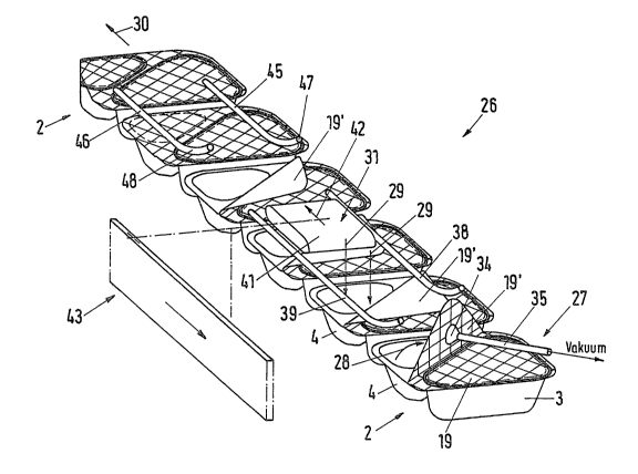
In Figure 2, an enlarged sectional representation
illustrates the apparatus 1, in which component parts are
disposed in the conveyor belt area 26 below the metering appara-
tus 25. With these component parts, the two-chamber containers,
supplied consecutively in a forward feeding direction 30, can be
uncovered in the region of chamber ~, filled, then cavered once
again and closed off by means of a second partial seal.
In an embodiment appropriate for this purpose, a
lifting element 27, which brings the respective unsealed covering
sheet area 19' of the two-chamber container 2 into an open posi-
tion, is provided immediately behind the severing station 22.
With this lifting element 27, the covering sheet area 19' can be
raised and tilted in the direction of arrow 28 as shown in Figure
9.
- 6 -
~. :~. ~ 1 °i :~.
After that, in a tilted position of the covering sheet
area 10 illustrated in Figure 10, the chamber 4 can be filled in
a supplying direction 29 without additional aids, the entry of,
for example, material containing dust-like structures withaut
affecting the material in chamber 3 also being possible.
With two-chamber containers 2 in different filling
phases as shown in Figure 2, it is made clear that,. after the
chamber 4 is filled in the direction of arrow 29, the unsealed
covering sheet area 19' now moves over a dosing element 31 into
a sealing position (Figure 1l) and, after that, the two-chamber
container 2 can be carried to a sealing station 32 (Figure 1)
forming the second partial seal in such a manner, that a fully
sealed two-chamber container 2 (Figure 12) can be removed at the
end of apparatus 1 by means of a transporting unit 33.
In Figure 9, an enlarged detailed representation illus-
trates two possible embodiments of the lifting element 27 or 27'
acting on the covering sheet area 19'. This lifting element 27
can be formed from a suction nozzle 35 with a suction cup 3~ as
well as from an emitter 36 with several nozzles 37.
Tn Figure 2, the use of the suction nozzle 35 is shown,
which tilts up the covering sheet area 19' in the direction of
the arrow by means of the suction cup 34. Tt is clear here that
a guiding element, which is connected in series with the forward
feeding equipment 30, overlaps the raised cover region 19' at
least in areas and is formed from two guiding rails 38, 39, is
provided in the region of the lifting element 27. With this
guiding element, the elastically tilted covering sheet area 19'
can be supported during the filling (in the direction of arrow
29) of chamber 4 in such a way, that the metering apparatus 25,
having a metering element, can be used with the least space fox
the filling process.
_ 7 _
~ ~. ~. ~ ~. ri :~.
It is advisable to provide the closing element 31,
which is constructed as a sliding rail 41 between the end region
of the two guide rails 38, 39 located in the forward feeding
direction 30. This closing element 31 can be shifted in a
direction of motion illustrated by arrow 42, so that the unsealed
covering sheet area 19, after the two-chamber container 2 is
filled, can be placed in the region of the second chamber 4 on
the edge flange 20 flush with the edge.
In Figures 3 and 4, different movement phases of a
driving unit 43 for driving the sliding rail 41 are shown. In an
appropriate embodiment, the sliding rail 41 is coupled with a
timing rake 44 intended for the transport of the two-chamber
containers 2 in such a manner, that the covering sheet area 19°
behind the guide rails 38, 39 can be taken hold of from behind
with the sliding rail 41, tilted into the covering position
(Figure 11, Figure 2) and introduced in this position into the
region of two parallel pressing rails 45, 46 (Figure 4). With
these pressing rails 45, 46 and their inlet curves 47, 48,
guidance for the covering sheet area 19° can be achieved with
little effort,'so that this covering sheet area 19° remains in
its covering position until the two-chamber container 2 enters
the sealing station 32. It would also be conceivable to reshape
the covering sheet material plastically in the area of its
tilting plane in such a manner, that the covering sheet 6 remains
in the closed position (Figure 11) on the container 2 without
spring-back, after which the second partial sealing takes place.
Figure 12 is a detailed representation illustrating the
two-chamber container 2 with a full seal, formed in the region of
the covering sheet 6 after passing through the sealing station
32. In this closed position, the covering sheet 6 is connected
by means of separate sealing seams 51, 52 with the sealing edge
20, which surround the chamber openings 3, 4. The connecting
_ g _
~1~~~'~~~.
part between the two chamber openings 3, 4 is formed with a
bridge width 53 accommodating the two sealing seams 51, 52
(Figure 13), which run at least in areas parallel. to the edges of
the two covered chambers 3, 4.
The sealing seams 51, 52 are formed over the consecu-
tive partial seals (Figure 1) on the sealing edge 20 and adapted
in their respective contours parallel to the edges of the
different covering sheet areas 19, 19'.
In the region of the connecting part between the
parallel sections of the sealing seams 51, 52 (Figure 13), the
container sheet 5 can be provided with a line of weakness 54,
which is constructed as a perforation and divides the bridge
width 53 into two partial areas of equal width and, when the two-
chamber cbntainer 2 is used, forms the intended break line.
In the area of the sealing seams 51, 52, the sealing
edge 20 can be provided at least near the chambers 3, 4 with
sealing beads shaped as an elevation towards the sealing sheet 6,
so that the seal, while retaining a reliable tightness, therewith
has a connecting plane, which can be cooled readily during the
closing process and opened more easily when the two-chamber
container is used.
The area of. the covering sheet 6, lying on the connect-
ing part in the sealing position, is furthermore provided with a
folding-over line 55, between the two parallel sealing seams 51,
52 (Figure 13). In the region of this folding-over line 55, a
swiveling axis for the opening of the chamber 4 (Figure 9),
necessary while filling the two-chamber container 2 or for the
subsequent covering, is formed and disadvantageous overloading of
the first partial seal in the parallel region of the sealing seam
51 is avoided.
- 9 -
I~~.~~~.~1.
Tn the embodiment of the two-chamber container 2 shown,
the connecting part, having the line of weakness ~4, is aligned
diagonally between the two chambers 3 and 4, while the basic
shape of the two-chamber container 2 is essentially rectangular.
However, the method and the apparatus for filling and closing the
two-chamber container 2 is not limited to this shape of contain-
er.
- 10 -