Note: Descriptions are shown in the official language in which they were submitted.
' n.
21143"1s
Tampon, especially for feminine hygiene, and process
and apparatus for producing it
The invention relates to a digital tampon for
feminine hygiene, with a recovery tape at its recovery
end, the tampon being formed from an approximately
cylindrical blank, shaped by winding up a length of
continuous fibre web, and narrow strip-shaped portions
of the circumferential surface of the wound blank
arranged at equal angular distances from one another
being pressed radially relative to the longitudinal
mid-axis of the latter to produce a preform which,.as
seen in cross-section, consists of an approximately
circular fibre core of high compaction and buckling
strength and of longitudinal ribs of softer fibre
structure with coarser capillarity, which extend
radially outwards from the fibre core and which are
separated from one another by outwardly open
longitudinal grooves, and only the soft longitudinal
t. ribs of the preform being exposed to a weak, uniform
pressure radial relative to the longitudinal mid-axis
of the preform, iri such a way that the outer ends of
the longitudinal ribs form a soft, essentially smooth-
cylindrical surface of smaller diameter corresponding
to the final shape of the finished tampon, with the
coarser capillary structure being maintained.
Tampons of this generic type are known from
DE 3,934,153 C2. They are, as a rule, packaged
individually and are introduced into the body cavity by
hand, without an introduction aid. In the proper
position or even in any position, the recovery tape
bears against the recovery end of the tampon or has
- 2 - 2WI14373
been pressed into this. After the individual pack has
been opened, therefore, the recovery tape first has to
be detached from the recovery end of the tampon, before
the digital tampon can be introduced. This detachment
of the recovery tape from the recovery end of the
tampon becomes a troublesome manipulation when the
recovery tape is anchored to a greater or lesser depth
or firmly in the pressed fibre composite of the tampon
during its production. There is provided for producing
this tampon a so-called progressive press, in which two
different groups of press jaws press the tampon in
succession to produce a preform, before the latter is
subsequently brought to the final shape of the finished
tampon in a die. This progressive pressing causes an
expansion of the tampon which is similar to the shape
of a quadrangle and as a result of which it is not
always possible to prevent some risk of leakage when
the tampon is employed. The tampon necessitates the use
of a relatively large amount of material, by means of
which a high stability or buckling strength of the
tampon desired for digital tampons is achieved.
However, this advantage is afforded at the expense of a
lower activatabilityof the fibre material, compacted
in the axial fibre core of the tampon, by fluid coming
into contact with this fibre material, thus
contributing, in conjunction with a heating of the
fibre material during the pressing of the latter, to an
impairment of the absorbency and speed of absorption.
Once the recovery tape has been detached from
the recovery end of the tampon before the introduction
of the latter, the tampon, after being inserted into
the body cavity, is introduced into the body cavity
completely by means of a finger by the exertion of
pressure on the recovery end of the tampon. This
complete introduction of the tampon can also present
difficulties, because a finger can slip off from the
recovery end of the tampon as a result of deficient
guidance. Moreover, relatively firm fibre consistency
'~ ~~.4373
i~d _
- 3 -
of the tampon additionally entails psychological
problems which can be detrimental to the acceptance of
the tampon. Since fibre material can build up between
the centrally arranged press jaws, which influences the
pressing of said fibre material and can no longer be
smoothed onto the surface of the tampon, the fibre
material remains visible as a narrow fin which is
undesirable both for psychological and for
physiological reasons.
The object on which the invention is based is,
therefore, to improve a digital tampon of the known
generic type mentioned in the introduction, in such a
way that the digital tampon has a fin-free, essentially
continuously smooth-cylindrical, soft surface and can
be introduced into the body cavity more safely and with
greater comfort. To reduce the risk of leakage, the
tampon is to expand to a circular-cylindrical cross-
section, have a lower weight of fibre material used,
but nevertheless achieve a high rate and degree of
expansion, along with a correspondingly high fluid
absorbency and retention, whilst maintaining the
necessary stability.
This object is achieved, according to the
invention, in that the preform, before being pressed to
the final shape of the tampon, is shaped by the
separate, but simultaneous radial pressing of directly
adjacent sectors of its entire circumferential surface
to produce a longitudinal groove and a longitudinal rib
respectively on each sector of the circumferential
surface of the preform, the longitudinal groove and
longitudinal rib which are assigned to each sector of
the circumferential surface being respectively arranged
in succession in the same order in a circumferential
direction of the preform, and the longitudinal grooves
being pressed radially to a lesser extent, at least in
the region of its recovery end.
The invention relates, furthermore, to a
process for producing a tampon for feminine hygiene, in
- 4 -
which, as in DE 3,934,153 C2, an essentially cylind-
rical blank is formed by winding up a length portion
provided with a recovery tape and consisting of
continuous random fibre web, narrow strip-shaped
portions of the circumferential surface of the wound
blank arranged at equal circumferential angles from one
another being pressed to produce a preform which, as
seen in cross-section, consists of a central fibre core
of high compaction and buckling strength and of
longitudinal ribs of softer fibre structure and coarser
capillary structure, which extend radially outwards
from the fibre core and which are separated from one
another by outwardly open longitudinal grooves, and
only the soft longitudinal ribs of the preform being
exposed to a weak, uniform pressure which is radial
relative to the longitudinal mid-axis of the preform,
in such a way that the outer ends of the longitudinal
ribs form a soft, essentially smooth-cylindrical
surface of smaller diameter corresponding to the final
shape of the tampon, with the coarser capillary
structure being maintained.
This process is improved according to the
invention in that a plurality of identical, directly
adjacent sectors of the entire circumferential surface
of the wound blank are separated, but at the same time
pressed, in one operation to the final shape of the
preform which is approximately round in cross-section,
as a result of the pressing each sector being provided,
only on a narrow strip-shaped portion, with a
longitudinal groove forming the central fibre core and,
only on a portion which is adjacent in a specific
circumferential direction of the wound blank and which
extends over a larger circumferential angle, with a
longitudinal rib, and, at least in the region of the
end provided with the recovery tape, the fibre material
on the narrow circumferential portions of the wound
blank being subjected to a lower radial pressing force
than the remaining fibre material.
- 5 - 2114373
Finally, the invention is also directed at an
improvement of the apparatus according to DE 3,934,153
C2 for producing a tampon for feminine hygiene and for
carrying out the above-described process. The apparatus
consists of a preforming press for pressing a preform,
with press jaws which are arranged in a plane
perpendicular to the press axis and are movable
radially relative to the press axis and which, in their
closed position, are supported relative to one another
on their mutually opposite longitudinal sides, in the
closed state of the press jaws the end faces of the
latter forming an essentially cylindrical, stepped
pressing surface, and with a stationary die which
follows the preforming press coaxially relative to the
press axis and the inlet orifice of which matches the
diameter of the orifice of the preforming press in the
closed state of its press jaws and the outlet orifice
of which matches the final cross-section of the tampon.
The invention provides an improvement of this
apparatus, in that all the press jaws have identical
dimensions and are arranged so as to be movable
concentrically relative to the press axis synchronously
between their closed position and open position, each
press jaw being provided with only one pressing head
directed radially relative to the press axis and with
only one pressing shoulder which is provided,
eccentrically to the pressing head, only on a specific
lateral flank of the latter which is respectively
directed in the same circumferential direction about
the press axis, each pressing shoulder being offset
outwards radially relative to the press axis in
relation to the end pressing surface of the pressing
head and having a larger pressing surface than the
pressing head, and, in the closed state of the press
jaws, the radial distance between the pressing surface
formed respectively by the pressing heads and the press
axis being made greater at least in the region of the
exit side of the press orifice than on_its entry side.
-6- Z114373
Since each sector of the circumferential
surface of the preform corresponds respectively to the
shape of the pressing surface of a press jaw and is
therefore provided, during pressing, only with a
longitudinal groove and a directly adjacent
longitudinal rib respectively, during the simultaneous
pressing of the longitudinal groove of the sector
adjacent in a circumferential direction of the preform,
the fibre material, involved in forming a fin, of the
longitudinal rib of the sector preceding in the
circumferential direction of the preform has been taken
up into the longitudinal groove from the outside of the
longitudinal rib towards the inside of the preform as a
result of the friction exerted between the press die
and the fibre material during the pressing. An
essentially smooth-cylindrical soft surface of the
tampon is therefore obtained, and only a hint of the
longitudinal grooves closed on the circumferential
surface of the tampon can be seen.
Because the tampon is shaped in a single
operation, as a result of the concentric, synchronous
closing movement of the press jaws of the preforming
press, to produce the prepressed tampon or preform
which is subsequently brought to the approximately
circular-cylindrical final cross-section of the
finished tampon merely by gentle smoothing, the central
fibre core is centred as exactly as possible relative
to the longitudinal mid-axis of the tampon, so that a
high buckling strength is ensured. At the same time, a
fraction of the fibre material in the region of this
fibre core is highly compacted, so that the fibre core
has a small diameter of, for example, only 5 mm.
Consequently, a larger quantity of less
compacted fibre material is available and can be
activated immediately by fluid coming into contact with
it. When wetted with fluid, the tampon endeavours to
expand to the original, circular-cylindrical cross-
section of the wound blank, and therefore the risk of a
CA 02114373 2006-07-19
77060-11
- 7 -
leakage is reduced. The lower compaction of the fibre
material in the region of the recovery end of the tampon
also contributes to this, even though the main purpose of
this lower compaction is aimed at making it easier for the
user to grasp the recovery tape and at shaping a finger
recess in the recovery end of the tampon. This also applies
when a finger recess is already shaped in the recovery end
of the tampon as a result of axial pressing. Since the
front end face of each press jaw consists respectively of
only one pressing head and only one pressing shoulder which
is itself always arranged only on a lateral flank of the
associated pressing head located in a circumferential
direction of the press axis, any fin formation on the
surface of the preform or of the finished tampon is avoided.
According to one aspect of the present invention,
there is provided a tampon for feminine hygiene, having an
insertion end, a recovery end, and a central portion
therebetween, comprising: a compressed, generally
cylindrical solid, fibrous core from which relatively
uncompressed longitudinal ribs extend radially outward, each
of the ribs being separated from adjacent ribs proximate the
compressed core by an amount greater than such rib is
separated from an adjacent rib distal the compressed core,
wherein the core is compressed to a greater extent proximate
the central portion of the tampon than proximate the
recovery end of the tampon.
According to another aspect of the present
invention, there is provided apparatus for producing a
tampon having an insertion end and a withdrawal end
comprising: a preforming press for pressing a preform
having a press axis, an inlet orifice, an outlet orifice,
and a plurality of similarly configured press jaws arranged
in a plane perpendicular to the press axis, each press jaw
CA 02114373 2006-07-19
77060-11
- 7a -
having a press head which is directed radially toward the
press axis, a press shoulder which is laterally adjacent the
press head, is displaced radially outward from the press
head, and has a larger pressing surface than the press head,
wherein the press jaws are simultaneously movable
concentrically relative to the press axis between a closed
position and an open position and, in the closed position,
the press jaws are supported relative to one another on
mutually opposite longitudinal sides and the radial distance
between the press axis and a press head proximate one of the
inlet orifice and outlet orifice is greater than the
distance between the press axis and the press head proximate
the other of the inlet orifice and the outlet orifice; and a
stationary die which is coaxial with the press axis of the
preforming press, has an inlet orifice which corresponds to
an outer diameter of the preform, and has an outlet orifice
which corresponds to an outer diameter of the tampon.
According to still another aspect of the present
invention, there is provided a process for producing a
tampon having an insertion end and a withdrawal end, the
process comprising the steps of: winding up a length of a
continuous fibrous web to form a generally cylindrical
tampon blank having a circumferential surface;
simultaneously pressing spatially separate, narrow, strip-
shaped portions of the circumferential surface of the tampon
blank radially inward in a simultaneous manner to form a
plurality of longitudinal grooves separated by relatively
uncompressed longitudinal ribs which extend radially outward
from a relatively compressed core, wherein the core is
compressed to a lesser extent proximate the withdrawal end
of the tampon than other portions of the tampon core; and
pressing outer ends of the longitudinal ribs radially inward
to form a soft, smooth, circumferential surface, while
CA 02114373 2006-07-19
77060-11
- 7b -
maintaining the relatively uncompressed fibrous structure of
the ribs.
The invention is explained in more detail below
with reference to the diagrammatic drawing of exemplary
embodiments of a tampon and of an apparatus for producing
this; in the drawing:
Figure 1 shows a diagrammatic view of a tampon
according to the invention;
Figure 2 shows a diagrammatic view of a further
embodiment of a tampon according to the invention;
Figure 3 shows a diagrammatic view of the use of a
digital tampon in Figure 1 or 2;
Figure 4 shows an apparatus for producing the
tampons according to Figure 1 or 2 in a longitudinal
section;
Figure 5 shows a section through a pressed tampon
preform along the line V-V in Figure 4;
Figure 6 shows a cross-section through a ready-
pressed tampon along the line VI-VI in Figure 4;
Figure 7 shows a view of the exit side of a
preforming press for the preform, with closed asymmetric
press jaws;
-a_ 431?
Figure 8 shows a top view of two press jaws of
the preforming press in Figure 7 located next to one
another, in a partially cut-away, enlarged
representation;
Figure 9 shows a view of a plurality of press
jaws in the closed state, which illustrates the
influence of an interspace on one side of each press
jaw on the fibre material of the preform;
Figure 10 shows a side view of a press jaw in
the direction of the arrow X in Figure 8 and its
fastening to fastening arms of the preforming press;
Figure 11 shows an enlarged side view of a
press jaw having a pressing blade for producing the
tampon in Figure 1;
Figure 12 shows an enlarged side view of a
press jaw having a pressing head for producing the
tampon in Figure 2;
Figure 13 shows a view of a smoothing bush;
Figure 14 shows a longitudinal mid-section of
the smoothing bush along the line XIV-XIV in Figure 13;
Figure 15 shows a diagrammatic view of the
smoothing bush according to Figures 13 and 14, with the
recovery tape and some pressing heads;
Figure 16 shows an elevation view of a hub;
Figure 17 shows longitudinal mid-section of the
hub in Figure 16 along the line XVII-XVII, and
Figure 18 shows an elevation view of a hollow
mandrel.
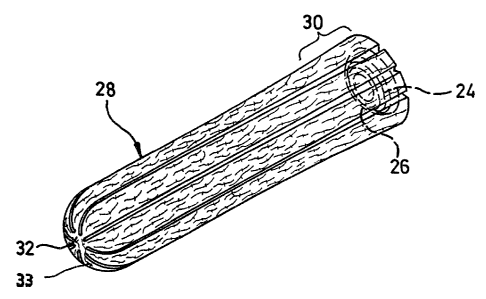
Figures 1 and 2 illustrate two embodiments of a
digital tampon 20; 28 according to the invention for
feminine hygiene, having a recovery tape 24 at its
recovery end 22; 30. The tampons 20; 28 each consist of
a web-shaped rectangular length portion (not shown) of
an essentially homogeneous continuous web of random-
laid natural fibres, such as cotton and/or viscose
staple fibres. This length portion is rolled up on
itself to form an approximately cylindrical wound
blank. Narrow strip-shaped portions of the
- 9 -
circumferential surface of this wound blank arranged at
equal angular distances from one another are pressed
radially relative to the longitudinal mid-axis of the
latter to produce a preform 42 in Figures 4 and 5
which, as seen in cross-section, consists of an
approximately circular fibre core 62 (Figure 5) of high
compaction and buckling strength and of longitudinal
ribs 64 of softer fibre structure with coarser
capillarity, which extend radially outwards from the
fibre core 62, the longitudinal ribs 64 being separated
from one another by outwardly open longitudinal grooves
180. Only the soft longitudinal ribs 64 of the preform
42 have been exposed to a weak, uniform pressure which
is radial relative to the longitudinal mid-axis of the
preform 42, in such a way that the outer ends of the
longitudinal ribs 64 form a soft,essentially smooth-
cylindrical surface 182 (Figure 6) of smaller diameter
corresponding to the final shape of the finished tampon
20; 28, with the coarser capillary structure being
maintained.
According to the invention, the preform 42,
before being pressed to the final shape of the tampon
20 or 28, is shaped as a result of the separate, but
simultaneous radial pressing of directly adjacent
sectors S of its entire circumferential surface 182 to
form a longitudinal groove 180 and a longitudinal rib
64 respectively on each sector S of the circumferential
surface 182. At the same time, each of the longitudinal
grooves 180 and each of the longitudinal ribs 64, which
are assigned respectively to one of these sectors S
(Figure 5) of the circumferential surface of the
preform 42, are arranged in succession in the same
order, as seen in the circumferential direction of the
preform 42. The fibre material of the preform 42 is
pressed radially to a lesser extent in the region of
the recovery end 22; 30. By means of axial pressing,
the recovery end 22; 30 of the tampon 20 or 28,
respectively, is provided with a finger recess 26, and
- 10 -
a front or introduction end 32 of the tampon 20; 28 is
provided with a round dome 33.
In the embodiment of the digital tampon 20
illustrated,in Figure 1, the rear or recovery end 22 is
widened in diameter by approximately 0.2 mm over an
axial length of approximately 8 mm. The fibre material
of the tampon 20; 28 therefore has a lower density in
the region of the recovery end 22 of the tampon 20 as a
result of the lesser pressing. The recovery tape 24 is
laid spirally against the finger recess 26. The second
embodiment of the digital tampon 28 shown in Figure 2
is widened conically and compacted to an increasingly
lesser extent over a length of approximately 15 mm in
the direction of its recovery end 30. Both digital
tampons 20; 28 have an essentially smooth circular-
cylindrical surface which feels agreeably soft.
According to Figures 5 and 6, the highly
compacted fibre core 62 of the digital tampons 20; 28
has a circular cross-section of only approximately 5 mm
with a lower weight of fibre material used and with the
necessary buckling strength being maintained, a high
rate and degree of expansion, along with a
correspondingly high fluid absorbency and retention,
being achieved.
The tampons 20, 28 are preferably surrounded by
a fluid-permeable sheathing (not shown) which covers
the circumferential surface of the approximately
cylindrical tampons 20 and 28 at least partially in
each case. This sheathing expediently consists of a
nonwoven material, the fibres of which have a
hydrophobic finish. The sheath of a material of this
kind makes it easier to introduce the tampons 20 and 28
into the body cavity and prevents the fibre fluff from
being detached when the tampon is being introduced into
or extracted from the body cavity. The sheath, as an
integral part of the portion of nonwoven web,
preferably already surrounds the circumferential
surface of the wound tampon blank completely or even
1137 3
- 11 -
only partially, in such a way that a length portion of
the tampon located in the region of the front or
introduction end is exposed. This ensures that, despite
the sheathing, the tampon can expand in an unimpeded
manner when fluid comes into contact with it. If
appropriate, however, the wound blank or even the
ready-pressed tampon can also be provided at its
recovery end with a sheathing which is wrapped round
the circumference of the blank or the tampon from this
end. The use of a heat-sealable sheathing material,
which, if appropriate, contains partially heat-sealable
fibres, such as, for example, so-called bicomponent
fibres, makes it possible, in exactly the same way as
natural adhesives, such as starch, to achieve a
sufficient fastening of the sheath to the fibre
material of the blank or tampon.
Figure 3 illustrates the use of a tampon 20 or
28 according to Figure 1 or 2, the part of a pack_.(not
shown) surrounding the recovery end 22 or 30 of the
tampon 20 or 28 being removed first. The tip of an
index finger 34-is thereafter inserted into the finger
recess 26 at the recovery end 22 or 30 of the tampon 20
or 28, and subsequently the rest of the packaging
material is removed, before the tampon 20, 28 is
introduced into the body cavity. The recovery end 22,
of the tampon 20, 28, said recovery end being
compacted to a lesser extent according to the
invention, makes it easier to shape the finger recess
26 and insert the index finger 34 into the finger
30 recess 26 of the tampon 20, 28. The softer nature of
the fibre material at the recovery end 22, 30 of the
tampon 20, 28 gives the user a more congenial feeling.
Furthermore, a more rapid expansion of the recovery end
22, 30 of the tampon 20, 28 is achieved, with the
result that the risk of a leakage shortly after the
tampon 20, 28 has been inserted into the body cavity is
reduced.
Figure 4 illustrates an apparatus for producing
- 12 -
a digital tampon 20 or 28 according to Figures 1 and 2.
It consists of a preforming press 36 having an entry
side 38 and an exit side 40 and serves for pressing the
preform 42 located in the preforming press. The
preforming press 36 is equipped with press jaws 58
which are arranged in a plane perpendicular to the
press axis A and are movable radially relative to the
press axis A and which, in their closed position, are
supported relative to one another on their mutually
opposite longitudinal sides. In the closed state of the
press jaws 58, the end faces of the latter form an
essentially cylindrical, stepped pressing surface, by
means of which one of a plurality of directly adjacent
sectors S of the entire circumferential surface of a
wound blank is loaded respectively for the purpose of
pressing a longitudinal groove 180 and a directly
adjacent longitudinal rib 64 (Figure 5).
The apparatus comprises, further, a die which
is designed as a heatable smoothing bush 48. This
smoothing bush 48 is arranged coaxially relative to the
press axis A of the preforming press 36 and is provided
with an inlet orifice 136, the diameter of which
corresponds approximately to the exit orifice of the
preforming press 36 in the closed state of its press
jaws 58. An outlet orifice 140 of the smoothing bush 48
is dimensioned according to the final cross-section of
the finished tampon 20, 28.
The preforming press 36 is preceded by a centre
sleeve 44 having a ram 46. The centre sleeve 44 is
arranged so as to be movable to and fro coaxially
relative to the axis of the preforming press 36 and
serves for pushing a respective wound blank into the
opened preforming press 36, the end of the wound blank
provided with the recovery tape 24 being at the front
in the pushing-in direction. The ram 46 is mounted in
the centre sleeve 44 so as to be displaceable to and
fro axially relative to the latter and serves for
pushing out the preform 42 in the preforming press 36.
133
- 13 -
As a rule, the front end face of the ram 46 is provided
with a recess, known per se and therefore not shown,
which resembles a spherical cup and by means of which
the introduction end of the preform 42 is shaped in the
manner of the round dome 33. In this case, there is
provided in a likewise known way a counter-ram (not
shown) which is moved up against the rear end of the
preform 42 at the moment when said ram 46 is moved up
against the front end of the preform 42. The end face
of this counter-ram is curved in the manner of a
spherical cup. Since an opposite axial pressing force
is exerted by the two rams on the preform 42 when the
latter is being ejected from the preforming press 36,
the finger recess 26, serving the purpose described
above, is formed in the rear end of the preform 42 by
the counter-ram.
The preforming press 36 with eight press jaws
58 is shown on a larger scale in its closed position in
Figure 7. All the press jaws 58 are identical in
respect of their shape and dimensions. Furthermore, the
press jaws 58 are arranged so as to be movable
synchronously into the closed or open position radially
and concentrically relative to the press axis A
(Figure 4) and, at the same time, are designed so that
the circumferential length of the press orifice formed
by the closed press jaws 58 corresponds to the
circumference of the wound blank (see also the cross-
section of the preform 42 in Figure 5). That is to say,
a shearing effect on the fibre material or on the
sheathing of the latter and an undesirable partial
overpressing of the fibre material are avoided. It has
been shown that the use of eight press jaws 58, in
conjunction with pressing heads 60 (Figure 8) of
specific dimension, results in the best possible
proportion by volume in a central fibre core 62 (Figure
5) and in the longitudinal ribs 64 of the preform 42
which extend radially from the fibre core 62. However,
depending on the desired tampon size, the even or odd
- 14 -
number of press jaws 58 can also be selected lower or
higher. As a result of the simultaneous closing
movement of the press jaws 58, a compaction, ensuring
the high stability of the digital tampon 20 or 28, of a
relatively small quantity of the fibre material is
obtained coaxially relative to the longitudinal mid-
axis of the preform 42 of essentially circular cross-
section, as can be seen from Figure 5. Consequently,
with a smaller amount of material used for the tampon
20, 28, a greater proportion of the fibre material used
can be activated by fluid coming into contact with the
tampon 20, 28 and can be utilised for the purpose of
higher fluid absorbency and expansion capacity.
This above-described functioning of the press
jaw 58 is promoted not only by their synchronous
closing and opening movement concentric relative to the
press axis A, but also by their special shaping and
fastening which are explained in more detail below.
According to Figures 7, 8 and 10, each press.
jaw 58 has a fastening foot 66 which is fastened
radially relative to the press axis A, on guide batons
88, 90 arranged parallel at a distance from one
another, by fastening means (not shown), such as
screws, and merges radially inwards into a T-profile
68. It is evident that a longitudinal mid-axis M of
each press jaw 58, which is directed radially relative
to the press axis A, passes through the longitudinal
centre of a vertical T-leg 70 of the T-profile 68. The
vertical leg 70 of this T-profile 68 forms, at the
inner end, a pressing head 60 having a narrow,
rectangular and plane end pressing surface 72. In
Figure 7, a pressing shoulder 74 extends from the
pressing head 60 transversely relative to this
eccentrically in an anti-clockwise direction and is set
back radially outwards relative to the pressing surface
72 of the pressing head 60 by an amount corresponding
approximately to the radial distance between the outer
surface of the longitudinal rib 64 and the outer
7 - 15 -
circumference of a fibre core 62 likewise of circular
cross-section. As shown more clearly in Figure 8,
lateral flanks 76, 78 of the pressing head 60 converge
in the direction of the pressing surface 72 at a very
acute angle of a few minutes over a length
corresponding approximately to the distance between the
pressing shoulders 74 and the end pressing surface 72
of each pressing head 60. This convergence of the
lateral flanks 76, 78 makes it easier for the pressing
heads 60 to release the fibre material and for the
preform 42 to be pushed out of the opened preforming
press 36. The longitudinal edges formed by the pressing
surface 72 and by the lateral flanks 76, 78 are
rounded.
The press core diameter W is determined in
that, on the one hand, the necessary absorbency of the
tampon 20 or 28 is maintained and, on the other hand,
the desired stability is achieved. According to Figures
7 and 9, in the closed state of the preforming press
36, the smallest lateral distance Y between adjacent
pressing jaws 58 is defined in that, during.pressing,
no fibre material 84 is cut and the preform 42
maintains the necessary shape. As emerges more clearly
from Figure 9, for this purpose there is an interspace
X which, furthermore, is intended to prevent the tampon
20, 28 from being pushed out. The interspace X, the
width of which amounts, for example, to 0.45 mm, is
limited respectively by mutually opposite longitudinal
sides of adjacent press jaws 58. At the same time, a
longitudinal side of each press jaw 58, said
longitudinal side being at the front in the clockwise
direction, forms a sliding face 80, opposite which a
longitudinal side, at, the rear in the clockwise
direction, of a press jaw 58 arranged respectively in
front in the clockwise direction is located, parallel
and at a distance, in the form of a supporting face 82.
This interspace X allows the fibre material 84 to be
taken up by the lateral flank 78 of each press jaw 58
- 16 - 43 Wd ~
located at the front in the clockwise direction, in
such a way that a fin formation on the outside of the
longitudinal rib 64 of the preform 58 is avoided and a
smooth, round outer face between the lateral flank 78
and the adjoining sliding face 80 of each press jaw 58,
on the one hand, and the supporting face 82 of a press
jaw 58 arranged in front in the clockwise direction, on
the other hand, is obtained.
Furthermore, it can be seen clearly from
Figure 8 that the interspace X between the adjacent
press jaws 58 is closed radially outwards by supporting
ribs 86 which have, in cross-section, an arcuate, for
example U-shaped, profile and which, in the closed
state of the press jaws 58, are supported on the plane
sliding face 80 of the respective adjacent press jaw
58. Lateral forces acting on each press jaw 58 are
thereby not transmitted to the guide batons 88, 90 for
the press jaws 58 (Figure 10). The accumulation of
fibre material 84 and its occasional settling on the
preform 42 are thereby prevented.
Figures 8'and 9 show that a pressing-shoulder
portion 92 in the form of a cylindrical cutout connects
the actual pressing shoulder 74 to the lateral flank 76
of each pressing head 60, in order to give the
longitudinal rib 64 of the preform 42 a round, smooth
shape also on the side facing away from the interspace
X. The pressing shoulders 74 of all the press jaws 58
have a concave shape and, for example, a radius of
curvature of approximately 6.4 mm.
Figure 7 illustrates that the radial parting
planes or planes of symmetry T, parallel to the press
axis A, between respective adjacent press jaws 58
intersect the press shoulders 74 perpendicularly at
their centre and respectively form the centre of the
press-jaw distance Y. An end of each pressing shoulder
74 located in the anti-clockwise direction in Figure 7
forms a shoulder edge 94 which merges at an obtuse
angle into the supporting face 82 of each associated
14 3?3
- 17 -
press jaw 58. The supporting face 82 of each press jaw
58 extends parallel to the sliding face 80 and
longitudinal mid-axis M of the respective press jaw 58
adjacent in the anti-clockwise direction and engages
respectively into a lateral cutout 96 of this press jaw
58. This cutout 96, which is accordingly provided
respectively on the side of each press jaw 58 located
at the front in the clockwise direction, is partially
cut into the vertical T-leg 70, extending along the
longitudinal mid-axis M of each press jaw 58, of each
press jaw 58, in the form of the sliding face 80
parallel to this longitudinal mid-axis. This sliding
face 80 is angled at 98 at an obtuse angle in the
clockwise direction at its end on the outside in
relation to the associated pressing head 60 and is
located, in parallel and at a distance, opposite a face
100 of the respective press jaw 58 located at the front
in the clockwise direction. Thereafter, these faces 80,
100 located opposite one another in parallel and at a.
distance are angled relative to one another in parallel
and at a distance in the direction of the parting plane
T in the region of the outer ends of horizontal
T-profile bars 102 and fastening feet 66 of the press
jaws 58. It is thus evident that the pressing shoulder
74 of each press jaw 58 engages beyond the associated
parting plane T into the cutout 96 of the adjacent
press jaw 58 and allows the asymmetric or one-sided
arrangement of the press shoulder 74, for the purpose
of pressing the fibre material 84 of the wound blank
inwards from the outside, while avoiding any fin
formation, and of shaping the essentially circular-
cylindrical outer contour of the preform 42.
The stationary, conical and heatable smoothing
bush 48 follows the preforming press 36 and is arranged
coaxially relative to the press axis A. The inlet
orifice 136 of the smoothing bush 48 is matched in
diameter to the orifice of the preforming press 36 in
the closed state of its press jaws 58. The outlet
1. 14373
18 -
orifice 140 of the smoothing bush 48 is dimensioned
according to the final cross-section of the finished
tampon 20 or 28.
A hub 50 follows the smoothing bush 48 likewise
coaxially relative to the press axis A. The hub 50 is
fastened to a turret disc 52 having a supporting guide
54, in which a hollow mandrel 56 is fastened by means
of the hub 50. The hollow mandrel 56 serves for
transferring the ready-pressed tampon 20; 28 into a
packaging sheath (not shown) consisting, for example,
of cellophane.
According to the invention, the wound blank is
first introduced into the preforming press 36 with its
rear end which has the recovery tape 24 and corresponds
to the recovery end 22; 30 of the tampon 20 or 28 and
which is therefore located in the region of the exit
side 40 of the preforming press 36.
The largest diameter of the press orifice is
located on this exit side 40 of the preforming press
36, the press orifice being made slightly conical
towards the exit end 40. The fibre core 62 (Figure 5)
of the preform 42 is thereby compacted to a lesser
extent in the region of its end provided with the
recovery tape 24, so that the fibre material is softer
at the recovery end 22, 30 of the ready-pressed tampon
20, 28, too, and the recovery tape 24 itself can easily
be detached by the user from the recovery end 30 of the
tampon 20, 28, before the tampon 20, 28 is used, as a
result of the softer consistency of the fibre material,
and the preshaped finger recess 26 can easily be
widened by the user before the tampon is introduced.
The softer fibre material at the recovery end 30 of the
tampon 20, 28 allows a better guidance of the latter
and makes it more agreeable to touch.
According to Figure 10, the pressing head 60 of
each press jaw 58 projects, with its side 106 facing
the smoothing bush 48, beyond an associated end 108 of
the pressing shoulder 74, the function of said end 108
- 219 - 11.~:373
being explained further below. Furthermore, the
fastening foot 66 of each press jaw 58 has two rear
fastening bores 110, 112 (Figure 7) which are arranged
at an equal distance from the longitudinal mid-axis M
of each press jaw 58 in a plane parallel to a rear edge
114 of the fastening foot 66. Located on the
longitudinal mid-axis M of each press jaw 58, at a
distance in front of the plane running through the
fastening bores 110, 112, is a further bore 116 which
extends through the fastening foot 66 in parallel with
the fastening bores 110, 112. The guide batons 88, 90
are each provided with three bores which are located
coaxially opposite one another in pairs and which are
aligned essentially with the fastening bores 110, 112,
116 in the fastening foot 66 of each press jaw 58. In
this way, the press jaws 58 can be releasably fastened,
for example by means of screws (not shown),
respectively to the two guide batons 88, 90 assigned to
them, parallel and at a distance and arranged in the
direction of the longitudinal mid-axis M of the press
jaws 58, and be moved radially to and fro.
Figure 10 shows only two coaxial bores 118, 120
in the guide batons 88, 90, which are assigned to the
bore 116 in the fastening foot 66 of each press jaw 58.
However, the bore 116 in the fastening foot 66 is
offset axially by an amount "X" in the direction of the
pressing heads 60 relative to the bores 118, 120 of the
guide batons 88, 90. A helical tension pin 122 is
inserted, according to Figure 7, into the bores 116,
118, 120 of each of the press jaws 58. This helical
tension pin 122 extends over the entire length of the
bores 116, 118, 120 and thereby ensures an identical
setting-up state of all the press jaws 58. In addition
to this dimensional equality, the helical tension pins
122 at the same time allow a resilient compensation
against possible lateral transverse forces which act on
the press jaws 58. In the closed state of the
preforming press 36, under working pressure, an
2114373
- 20 -
identical and centric closing diameter of the press
jaws 58 is always achieved thereby, this contributing
to ensuring ahigh fatigue strength of the preforming
press 36 and a constant high quality of the tampon as a
mass-produced product.
Figure 11 shows on a larger scale a press jaw
58, of which the end pressing surface 72 parallel
relative to the press axis A serves for producing the
tampon 20 in Figure 1. The pressing surface 72 has, at
its end 124 facing the smoothing bush 48, a clearance
126 which extends approximately parallel to the
pressing surface 72 and of which the length can be
approximately 8 mm and the depth approximately 0.2 mm
and the width of which corresponds to that of the
pressing surface 72. By means of this clearance 126,
the recovery end 22 of widened cross-section of the
tampon 20 in Figure 1 is obtained during the pressing
of the preform 42.
Figure 12 shows a press jaw 58 which
corresponds to the press jaw 58 in Figure 11, with the
exception of its essentially plane pressing surface 72.
Thi.s pressing surface 72 has, in particular in the
region of a lateral nose 128 facing the smoothing bush
48, a bevel 130 which terminates at an inclination of
an angle of approximately 0.76 and of which the
greatest depth at said nose 128 of the pressing surface
72 amounts to approximately 0.2 mm and which merges
into the plane pressing surface 72 over a length of
approximately 15 mm. The width of the bevel 130
corresponds, in turn, to that of the pressing surface
72. A preforming press 36 equipped with this bevel 130
of the pressing surfaces 72 of all the press jaws 58
serves for producing the conically widened recovery end
30 of the tampon 28 in Figure 2. It is evident that, as
a result of this above-described lesser pressing of the
fibre material of the tampons 20 or 28 by means of the
clearance 126 or bevel 130, the finger recess 26 can be
shaped more easily and the speed of absorption at the
~?114373
- 21 -
recovery end 22; 30 of the tampon 20, 28 can be
increased. If appropriate, said conical widening of the
press orifice, brought about by the bevel of the
pressing surface of the pressing heads 60, can also
already start on the entry side 38 of the preforming
press 36.
Figures 13, 14 and 15 show the smoothing bush
48 of Figure 3 on a larger scale. The smoothing bush 48
is located with its circular disc 132 in front of the
exit side 40 of the preforming press 36. The circular
disc 132 is provided with radial slots 134 which are
arranged at equal angular distances from one another
and into which the noses 128 respectively projecting
beyond the pressing shoulder 74 and belonging to the
pressing heads 60, engage so as to be radially movable
with lateral play, that is to say without being guided
by the slot 134, as a centring mounting for the
recovery tape 24 wound spirally during the production
of the wound blank. This function of the noses 128 can
be seen especially clearly in Figure 15, in which the
pressing heads 60 with their pressing surfaces 72 are
shown clearly narrower and shorter than the slots 134
are wide and deep, so that a clear distance 135 is
formed between the noses 128 of the pressing heads 60
and the slots 134. In the closed state of the press
jaws 58, the pressing surfaces 72 of the pressing heads
60 are aligned with the inner circumferential surface
of the inlet orifice 136 of the smoothing bush 48, so
that the spirally wound recovery tape 24 at the front
end of the preform 42 is guided in alignment with this
inlet orifice 136 and consequently maintains its spiral
shape.
According to Figure 14, the smoothing bush 48
has its largest free cross-section in the region of its
inlet orifice 136. The diameter of this inlet orifice
136 corresponds approximately to the largest clear
cross-section of the press orifice on the exit side 40
of the preforming press 36 in the closed state
1137 3
- 22 -
according to Figures 3 and 8, so that a reliable
ejection of the preform 42 from the preforming press 36
is ensured. -A final-shaping channel 138 narrows
conically from the circular inlet orifice 136 as far as
the outlet orifice 140 of the smoothing bush 48. The
conical shape is designed so that the least possible
ejection force is necessary in order to eject the
preform 42 out of the preforming press 36 into the
smoothing bush 48.
It is evident from Figure 14 that there project
from the inner wall of the final-shaping channel 138 a
number, corresponding to the number of press jaws 58,
of, in the present case eight, radial guide ribs 142,
the triangular cross-section of which tapers radially
inwards at 144. Two longitudinally extending flanks
146, 148 of 'the guide ribs 142 have a concavely shaped
cross-section and correspond approximately exactly to
the clear cross-section of the longitudinal grooves 180
between the longitudinal ribs 64 of the preform 42
which are produced by the press jaws 58. Figure 14
shows that the height of the guide ribs 142 increases
sharply from the inlet orifice 136 of the smoothing
bush 48 as far as an intersection point 150 of two
cones 152, 154 and subsequently narrows to a lesser
extent up to approximately 1 mm in front of the outlet
orifice 140. The final-shaping channel 138 thus
consists of a double cone 152, 154 and of the
cylindrical outlet orifice 140. For the most effective
possible pressing operation, in addition to the number
of press jaws 58, eight concave longitudinal slots 158
of a cross-section in the form of an arc of a circle
are correspondingly provided in the inner wall of the
final-shaping channel 138. The shape of the final-
shaping channel 138 has been determined by tests. The
shape described achieves an ideal course of the
pressing force, and the'tampon 20, 28 acquires the best
possible appearance. During the pressing of the preform
42, the guide ribs 142 ensure its exact axial guidance,
33
- 23 -
and at the same time the fibre material is displaced in
the best possible way while the preform 42 is being
pushed through. In order to reduce the wear and to
achieve good sliding properties when the preform 42 is
being pushed through the smoothing bush 48, the final-
shaping channel 138 of the latter is coated with a
hard-metal layer.
Figures 16 and 17 show the hub 50 which is
fastened by means of two fastening claws 160 to the
turret disc 52 by fastening means (not shown), such as
screws or the like. An intake orifice 162 is narrowed
slightly conically, the diameter of the intake orifice
162 being made slightly larger than the smallest bush
diameter of the smoothing bush 48. At approximately
mid-length, the intake orifice 162 merges into a
cylindrical part 164 which, in turn, corresponds
approximately to the final diameter of the smoothing
bush 48. The hub 50 is provided on the rear side with a
recess 166 which, as shown in Figure 4, is located
opposite the supporting guide 54 in the turret disc 52,
the function of which is described below.
Figure 18 shows the hollow mandrel 56 which is
provided, at its inlet end, with an annular flange 168,
from which centring batons 170 extend at intervals.over
the circumference of the hollow mandrel 56 on a length
which corresponds at most to the thickness of the
turret disc 52 in Figure 4. Provided at the lower end
of the annular flange 168 is a centring extension 172
which engages into a radial centring slot 174 on the
rear side of the hub 50. This ensures that the hollow
mandrel 56 can be inserted, with an orifice 176 sloping
obliquely downwards, into the turret disc 52 only in
the position shown in Figure 18. The hollow mandrel 56
preferably consists of plastic, but if appropriate it
can also be made of steel.
With the apparatus described, the process for
producing the digital tampon 20 or 28 in Figures 1 and
2 according to the invention is carried out as follows:
~~ ~ct4Jr~~~
- 24 -
First, an essentially cylindrical wound blank is shaped
in a way known per se, by winding up a length portion,
provided with a recovery tape 24, of a nonwoven web of
tangled natural fibres, in such a way that the recovery
tape 24 bears in the form of a spiral against one end
of the wound blank. Thereupon, this wound blank is
pushed coaxially into the opened preforming press 36 by
means of the centre sleeve 44, the flat end face of the
wound blank provided with the recovery tape 24 being
located at the front in the feed direction.
Subsequently, as shown in Figure 5, narrow rib-shaped
or strip-shaped sectors of the circumferential surface
of the wound blank, which are parallel relative to the
press axis A and which are separated from one another
by equal circumferential angles, are pressed radially
relative to the press axis A as a result of the
synchronous concentric closing movement of the press
jaws 58, and the longitudinal grooves 180 are formed.
Simultaneously, by means of the pressing
shoulders 74 of the same press jaws 58, which are
located respectively on that side of the associated
pressing head 60 directed in the anti-clockwise
direction according to Figure 7, larger portions of the
same sectors of the circumferential surface of the
wound blank are subjected to a pressing force to form
the longitudinal ribs 64. Consequently, the preform 42
is obtained in one work cycle of the press jaws 58
moving jointly into the closed position. During the
forming of the longitudinal grooves 180, the central
fibre core 62 of approximately circular cross-section
and of high compaction and buckling strength is
produced, whilst the longitudinal ribs 64 extend
radially outwards laterally of the longitudinal grooves
180 and have an increasingly softer fibre structure
with coarser capillarity towards the outside.
It is essentially in this pressing operation
that the lateral flanks 78 of each pressing head 60
take up in the direction of the press axis that fibre
- 25 -
material 84 which tends to penetrate into the
interspace X between a sliding face 80 and a supporting
face 82 of two adjacent press jaws 58 respectively, so
that a completely smooth soft surface is formed on the
outside of the longitudinal ribs 64. This effect can be
influenced by a specific surface nature of the said
lateral flank 78 of each pressing head 60 and by the
choice of the acute radially outward-opening angle
which the said lateral flank 78 forms in each case with
the longitudinal mid-axis M of the particular press
jaw.
After the preform 42 has been pressed, a
counter-ram (not shown) is moved through the hollow
mandrel 56, the hub 50 and the smoothing bush 48
coaxially up against the end of the preform 42 at the
front in the run-through direction, in the preforming
press 42, after the latter has been ventilated
slightly. At the same time, the ram 46 is moved up
against the end of the preform 42 at the rear in the
run-through direction. The two rams thereby exert an
oppositely directed axial pressure on the preform 42
which is consequently provided with the round dome 33
for the introduction end 32 of the tampon 20; 28 and
with the finger recess 26 for the recovery end 22; 30
of the tampon. During this relatively slight axial
{ pressing, the preform 42 is transferred into the hollow
mandrel 56 by means of the two rams. The noses 124 and
128 of the press jaws 58 ensure that the recovery tape
24 attached spirally to the front end of the preform 42
maintains its position perfectly .during the transfer
into the smoothing bush 48.
At the same time, only the soft longitudinal
ribs 64 of the preform 42 are exposed, in the smoothing
bush 48, to a weak, uniform pressure concentric
relative to the longitudinal mid-axis of the preform 42
and are smoothed, along with exact longitudinal
guidance, to the essentially smooth-cylindrical final
shape of the tampon 20 or 28 according to Figure 1 or
~1.1.437 3
- 26 -
2, the fibre structure being stabilised (Figure 6). The
coarser capillarity of the fibre material 84 located
outside the fibre core 62 is maintained in the finished
tampon 20; 28. The smoothing effect is preferably
reinforced by a heating of the preform 42 by means of
the smoothing bush 48 equipped with heating elements.
The synchronous closing movement of the press
jaws 58 to the final diameter of the fibre core 62 of
the tampon 20, 28 is essential, because, with a smaller
quantity of fibre material, a high buckling strength
and a uniform expansion of the tampon when wetted with
fluid are guaranteed. In particular, the design
according to the invention of the press jaws 58,
together with the eccentric arrangement of the pressing
shoulder 74 on only one side of the pressing head of
each press jaw 58, ensures that at least the fibre
material located in the region of the recovery end 22
or 30 of the tampon 20 or 28 has an overall lower
compaction than the remaining fibre material of the
tampon. Consequently, the recovery tape 24 of the
tampon 20 or 28 is embedded into the less compacted
fibre material of the recovery end 22 or 30 of the
tampon 20, 28 and can more easily be detached by hand
from this fibre composite, with a finger recess 26
thereby being formed or widened. In addition, a higher
speed of expansion of the fibre material, which
counteracts a leakage shortly after starting to use the
tampon, is achieved in the region of the recovery end
of the tampon.
In the above-described process for producing
the tampon 20, 26, it is also possible, if appropriate,
to bring about the lower compression of the fibre
material at the recovery end by means of the pressing
surface 126, offset in a step-like manner, of the
pressing heads 60 in Figure 11. Moreover, it would be
possible, if appropriate, to press the longitudinal
grooves of the preform 42, starting at its front or
introduction end, over its entire length to an
21 It 4 3 7 3
- 27 -
increasingly lesser extent in the direction of the
recovery end.