Note: Descriptions are shown in the official language in which they were submitted.
The invention relates to a hinge pin device for a
vehiale track havina hinaed links.
Known tracks for motor-driven vehicles, whether
civilian vehicles such as earth-moving eguipment, or
; military vehicles such as tanks, ar~ constltuted by shoes
assembled to one another by "dry pin" connections, or in
a variant by links, in which case the track is
constituted by shoes pierced by through bores or holes in
which hinge pins are force-fitted, which pins are
connected together by rigid links (see FR-2 623 767, for
example). In a common configuration, links that carry a
drive tooth are disposed between two adjacent shoes,
whereas other links are disposed on the outsides of said
shoes. Compared with "dry pin" tracks, a track made in
this way has the advantage of providing double hinges
between adJacent shoes, and consequently of increasing
flexibility when overcoming obstacles. In addition, when
the pins are fitted with blocks of rubber, then they are
capable of absorbing rotation of the pins relative to the
shoes, by shear deformation of the rubber, in contrast to
tracks that are assemhled ~sing "dry pins" where rotation
takes place with friction.
In spite of their advantages over "dry pin" tracks,
particularly with respect to reliability (no danger of
the shoe eyes cracking), reduction of vibration
(particularly important for vehicles that carry
electronic or other apparatus that is sensitive to such
vibration), and reduction of "a~oustic signature", tracks
having links nevertheless suffer from drawbacks of price,
of possible deformation in traction, and of insufficient
hinge pin lifetime compared with the lifetime desired for
a track, consequently giving rise to maintenance costs
and periods during which the vehicles fitted with such
tracks are unavailable. With such devices, it has also -
-~` 2 ~ 0 ~
been observed that the rubber used deteriorates rapidly,
and as a result the hinge pin itself is degraded, with
thls being due to the cyclical deformation applied
thereto, which deformation heats up the elastomer, given
the phenomenon of hysteresis.
Although the Applicant has already provided
improvements to the hinge pin devices described above by
proposing, in FR-A-2 623 767, a pin having resilient
blocks of compressed rubber extending over a fraction
only of the length of the pin by being disposed thereon
solely in zones that correspond to the vicinity of the
lateral front faces of the shoe(s) when the pin is
mounted in the shoe(s), it turns out that still better
performance can be obtained in the hinge pin devices of a
vehicle track having hinged links, in particular with
respect to flexibility in torsion and rigidity in
traction.
According to the invention, the problem thus posed
of providing a hinge pin device for a track having hinged
links presenting great flexibility in torsion and great
rigidity in traction, in which the heat energy generated
in operation is low, in which lifetime is long, and which
is also capable of being implemented wi~hout modifyin~
the other component elements of the track, in particular
the dimensional characteristics thereof, such as the
thickness of the shoes which is specified by vehicle
manufacturers, is resolved by the fact that the resilient
blocks of rubber or analogous elastomer material that
30 extend over the entire length of the pin are disposed in ~
two coaxial assemblies with a metal tube being lnterposed ~ -
between them, the rubbers or elastomer materials
constituting the first and second assemblies being
different, in particular with respect to their mechanical
characteristics, and in particular their shear moduluses,
the blocks of the first assembly being secured to the
outside surface of the pin whereas the blocks of the
;,: , ::: ;~. :
6 0 ~
second assembly are secured to -the outside surface of the
metal tube.
The desired flexibility in torsion is thus obtained,
thereby enabling the track to wind properly around the
wheels, the tensioner pulley, and the sprocket wheel,
while simultaneously overcoming roughnessss and obstacles
on the ground satisfactorily with the stiffness in
traction that is required to ensure that the sprockets of
the sprocket wheel mesh properly and to avoid any risk of
the track coming off (due to excessive lengthening
thereof).
Where appropriate, the first blocks may also be
secured to the inside surface of the metal tube, and the
second blocks may be secured to the shoes in which the
hinge pins are received so as to counter any possible
longitudinal sliding of said blocks.
The invention also provides for the ratio of the
shear moduluses of the materials constituting the first
and second blocks to have a value of the order of 1.2 to
0.8.
In a preferred embodiment, the first blocks are made
of a material based on polyisoprene or on natural rubber
having a hardness of about 68 on the Shore A scale and a
shsar .~.o-ulus of about 1.2 MPa, whereas the second blocks
are made of a material based on polyisoprene or on
natural rubber having a hardness of the order of 55 on
the Shore A scale and a shear modulus of about 0.8 MPa.
The material(s) constituting the first and second
blocks is(are) preferably selected from materials having
excellent resistance to fatigue, very good resistance to
rupture, low residual deformation on compression, and
good resilience (tan ~ less than 0.20).
The number of first and second blocks that are
distributed almost in contact with one another along the
entire length of a hinge pin (naturally with the
exception of the zones of the pin that co-operate with
the links), and the shape of said blocks are preferably
2 1 1 1 6 0 1
selected to limit the prestresses that result from force-
fitting the pin in the shoes.
In a preferred embodiment, the blocks which are made
of rubber or of analogous elastomer material, have a
substantially trapezoidal right cross-section with a
large base that is secured to the pin proper, in the case
of the first blocks, and to the intermediate ~etal tube
in the case of the second blocks, and the first blocks,
where appropriate, are also secured to the intermediate
me~al tube, whereas the second blocks, where appropriate,
are also secured to the shoes.
Other features and advantages of the invention
appear from the following description given by way of
example and made with reference to the accompanying
drawings, in which: ..
Figure 1 is a diagrammatic perspective view of a
portion of a track fitted with links;
F~gure 2 is a corresponding, partially-cutaway
diagrammatic plan view;
Figure 3 is a diagrammatic explanatory view showing
the structure of a hinge pin of the invention prior to
installation and for two different stages in the
manufacture of sai- pin; and
Figure 4 is a section view through a hinge pin of:~:
the invention when installed in two shoes. ` :
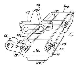
Reference is made initially to Figure l which shows
the structure of a track for a vehicle having hinged
links. The track is made up of shoes 101 and lQ2 each
carrying a pad 22 of rubber or the like on its bottom
face for the purpose of coming into contact with the
: ground, the shoes being interconnected by hinge pins 11
and 12 that are received in throuyh bores or holes 13 and
14 in the shoes extending substantially perpendicularly
to the direction in which the track is wound round the
sprocket wheel, as shown by arrow F. The ends of the
-~" 2~1~6~:1
pins 11 and 12 lying outside the shoes are interconnected
(over the lateral front faces 20 of the shoes of the
track) by means of rigid links 15 and 16, Figures 1 and
2, whereas central links 17 located between the shoes 10
and 102 carry respective drive teeth 18 and interconnect
the middle portions of pins 11 and 12.
In known embodiments of hinged-link tracks, the pins
11 and 12 are force-fitted in the through holes 13 and 14
in the shoes 10 and they are provided with sleeves or
washers of rubber or analogous elastomer material that
are referred to herein as "blocks" and that comprise
rings of rectangular right cross-sectlon that are spaced
apart from one another along the pin, with gaps naturally
being left over those portions of the pin that are
designed to co-operate directly with the links 15, 16, or
17. The flexibility in torsion of such hinges which
allows sufficient relative rotation to enable thP. track
to pass round the sprocket wheel, the tensioning pulleys,
and/or the wheels of the driving equipment of a vehicle
fitted with such tracks, also gives rise to a certain
amount of flexibility in traction which is itself the
: cause of excessive deformation in traction that can lead
to the track being lengthened so much as to make it
possible for the track to come off. P~other consequence
of flexibility in traction is that energy is lost due to
such deformation in traction, thereby giving rise to
relatively major deterioration in the blocks of rubber ~:
and consequently in the pin itself, due to the thermal
energy generated in the blocks while the track is in
operation, because of the hysteresis of the rubber~
To mitigate these drawbacks, without interfering
with the flexibility in torsion of the hinge, and also
without reducing lifetime, and finally without modifying
the other component parts of the track, and in particular
the dimensions of the forged parts used for making the
shoes 10, the invention proposes that each hinge pin 11,
12 which is constituted as a hollow pin having an end
flat 25 for fixing the outside links 15 and 16, be
associated with two sets of blocks that are separated
from each other by an intermediate metal tube (see
Figures 3 and 4).
More precisely, the invention proposes lining the
hollow pins 11, 12 with a set of first blocks 301, 32~
303, . . . ( Figure 3) disposed almost touching one another
on the pin 11, 12, with each block being an annular block
of rubber or analogous elastomer material that is shaped
so as to have a right cross-section that is somewhat
trapezium-shaped, the inside surface thereof (i.e. the
surface corresponding to the larger base 31) being
securely bonded to the outside surface 32 of the pin 11,
12. As shown in Figure 3, the outside diameter d of the
blocks 30 while in the free state is slightly greater
than the inside diameter D of a metal tube 35 on which
second blocks 361, 36z, ..., of rubber or analogous
elastomer material are fixed, which blocks are similar in
shape to the blocks 30 and are likewise disposed along
the entire length of the tube 35, substantially in
touching contact, and are securely bonded via their
inside surfaces 37 to the outside surface 38 of the metal
tube 35. As for the first blocks 30, the outside
diameter e in the free state of the blocks 36 is slightly
25 greater than the inside diameter of the bores 13, 14 in :
the shoes 10 such that when tha pin 11, 12 including the
first and second blocks is forced into the bores 13, 14
of the shoes, the second blocks 36 are prestressed,
thereby occupying substantially all of the volume of the
bore, and likewise the first blocks 30 are also
prestressed inside the intermediate metal tube 35 where
: they too also occupy substantially all of the volume
(Figure 4).
~he generally trapezium-shaped outline of the right
cross-section of the blocks 30 and 36, and the number and
proposed touching distribution thereof make it possible
(after the tube 35 lined with the blocks 36 has been
` 21`1~60~
mounted on the pin 11, 12 lined with the blocks 30 in a
coaxial configuration by using a bushing having a conical
passage, and then by mounting the pin in the shoes), to
conserve as low as possible a level of Von Mises stresses
in the rubber or analogous elastomer material from which
the said blocks are made, while still taking advantage of
the prestress to which they are subjected, thus
establishing an element that favors improvement in the
fatigue behavior of the pin and also favors increasing
its rigidity in traction.
In one embodiment, the blocks 30 are bonded via
their outslde surfaces 33 to the tube 35 while the blocks
36 ara bonded via their outside surfaces 39 to the shoes.
Although the materials constituting the blocks 30
and the blocks 36 are advantageously both based on
polyisoprene or on natural rubber having excellent
resistance to fatigue, very good resistance to rupture,
low residual deformation in compression, and good
resilience (tan ~ less than 0.20), they are nevertheless
selected to have mechanical characteristics which are
different, the shear modulus of the elastomer material
for the blocks 30 being selected to be greater than that
of the blocks 36, mainly to ensure that the lifetime of
the first and second blocks is the same in spite of the
fact that they are subjected to different stresses.
In one embodiment of a pin of the invention, each
bearing sur~ace is about 230 mm long and is lined with 14
blocks, each block having a trapezium-shaped right cross-
section with its large base fixed to the intermediate
metal tube 35 or to the hollow pin 11, 12. The blocks
are disposed so that they are substantially touching, the
material for the first blocks being selected from natural
rubbers having a hardness on the Shore A scale of 68 and
a shear modulus of about 1.2 MPa, while the material of
the second blocks is a natural rubber having a hardness
of 55 on the Shore A scale and a shear modulus of about
0.8 MPa. With the above embodiment, it has been observed
. .
-- 2 1 ~ 0 ~
during testing that the lifetime of the pin is greater
than that of previously known embodiments, without any
reduction in flexibility in torsion, but, in contrast,
with an increase in stiffness in traction that may be as
much as 80%, and with a reduction in the amount of
thermal energy that is dissipated in use.
Although the invention is described above with
Reference to a track having adjacent shoes 101 and 102,
the invention i5 naturally not limited in any way thereto
and can be applied to tracks having single shoes, without
any central link, or in a variant to tracks having more
than two ad~acent shoes, and therefore having a plurality
of central links.