Language selection

Search

Patent 2114602 Summary

Third-party information liability

Some of the information on this Web page has been provided by external sources. The Government of Canada is not responsible for the accuracy, reliability or currency of the information supplied by external sources. Users wishing to rely upon this information should consult directly with the source of the information. Content provided by external sources is not subject to official languages, privacy and accessibility requirements.

Claims and Abstract availability

Any discrepancies in the text and image of the Claims and Abstract are due to differing posting times. Text of the Claims and Abstract are posted:

  • At the time the application is open to public inspection;
  • At the time of issue of the patent (grant).
(12) Patent: (11) CA 2114602
(54) English Title: BACKWATER VALVE
(54) French Title: CLAPET DE RETENUE
Status: Expired
Bibliographic Data
(51) International Patent Classification (IPC):
  • E03F 7/04 (2006.01)
  • E03B 7/07 (2006.01)
(72) Inventors :
  • COSARELLA, GABE (Canada)
  • CHIODO, VITTO (Canada)
(73) Owners :
  • COSARELLA, GABE (Canada)
  • MAINLINE BACKFLOW PRODUCTS INC. (Canada)
(71) Applicants :
  • COSARELLA, GABE (Canada)
  • CHIODO, VITTO (Canada)
(74) Agent: WOODRUFF, NATHAN V.
(74) Associate agent:
(45) Issued: 1997-07-01
(22) Filed Date: 1994-01-31
(41) Open to Public Inspection: 1995-08-01
Examination requested: 1996-09-10
Availability of licence: N/A
(25) Language of filing: English

Patent Cooperation Treaty (PCT): No

(30) Application Priority Data: None

Abstracts

English Abstract


A backwater valve is described which includes a liquid
retaining body having a top, a bottom, a first end, a second
end, opposed sides and an inner chamber. A first flow conduit
extends through one of the top of the body and the first end
adjacent the top of the body and protrudes into the inner
chamber. A second flow conduit extends from the inner chamber
through the second end adjacent the bottom of the body and
protrudes past the second end. An annular seal is positioned
on an annular peripheral edge of the first flow conduit which
protrudes into the inner chamber. A plate is pivotally mounted
to the body. The plate having a wear resistant lubricious
first face, a second face, a first end and a second end. The
first end underlies the first flow conduit. The first face
extends past the first flow conduit thereby serving as a
spillway for liquids flowing through the first flow conduit.
The plate is pivotally movable between a closed position and
an open position. In the open position the first face engages
the annular seal. In the open position the first face is
spaced from the annular seal. The plate is maintained in a
normally open position by force of gravity. A float is
secured to the second face of the plate such that the plate
floats into the closed position when the inner chamber is
filled with liquid.


French Abstract

Clapet anti-refoulement comportant un élément retenant les liquides, composé d'une partie supérieure, d'une partie inférieure, d'un premier bout, d'un deuxième bout, de côtés opposés et d'une chambre interne. Une première conduite passe à travers la partie supérieure de l'élément et le premier bout, adjacent à la partie supérieure, et sort dans la chambre interne. Une deuxième conduite part de la chambre interne, passe à travers le deuxième bout, adjacent à la partie inférieure, et sort de l'autre côté du deuxième bout. Un joint d'étanchéité annulaire est placé dans une gorge annulaire périphérique de la première conduite qui débouche dans la chambre interne. Une plaque pivotante est fixée à l'élément. Cette plaque comporte une première face lubrifiée résistante à l'usure, une deuxième face, un premier bout et un deuxième bout. Le premier bout se trouve sous la première conduite. La première face dépasse la première conduite, servant donc de déversoir pour les liquides coulant de la première conduite. La plaque pivotante peut être en position fermée ou ouverte. En position ouverte, la première face engage le joint d'étanchéité annulaire et, en même temps, en est séparée. La plaque demeure dans une position normalement ouverte grâce à la gravité. Un flotteur est fixé à la deuxième face de la plaque de façon à ce que la plaque flotte jusqu'en position fermée lorsque la chambre interne est remplie de liquide.

Claims

Note: Claims are shown in the official language in which they were submitted.


THE EMBODIMENTS OF THE INVENTION IN WHICH AN EXCLUSIVE PROPERTY
OR PRIVILEGE IS CLAIMED ARE DEFINED AS FOLLOWS:

1. A backwater valve, comprising:
a. a liquid retaining body having a top, a bottom, a
first end, a second end, opposed sides and an inner chamber;
b. a first flow conduit extending through one of the top
of the body and the first end adjacent the top of the body and
protruding into the inner chamber;
c. a second flow conduit extending from the inner chamber
through the second end adjacent the bottom of the body and
protruding past the second end;
d. an annular seal on an annular peripheral edge of the
first flow conduit protruding into the inner chamber;
e. a plate pivotally mounted to the body, the plate
having a wear resistant lubricious first face, a second face,
a first end and a second end, the first end underlying the
first flow conduit, the first face extending past the annular
peripheral edge of the first flow conduit and surrounding at
least a portion of the conduit thereby serving as a spillway,
the plate being pivotally movable between a closed position in
which the first face engages the annular seal and an open
position in which the first face is spaced from the annular
seal, the spillway thereby preventing fluid overflow and
accumulation of debris between the bottom of the liquid
retaining body and the plate as the plate moves from a closed
position to an open position; and
f. the plate being maintained in a normally open position
by force of gravity, a float being secured to the second face
of the plate such that the plate floats into the closed
position when the inner chamber is filled with liquid.

2. The backwater valve as defined in Claim 1, wherein the
plate has opposed sides in close proximity to the opposed sides
of the body thereby preventing hair, toilet paper and other
debris from passing between the sides of the plate and sides
of the body.


3. The backwater valve as defined in Claim 1, wherein the
first face of the plate has sidewalls such that the first face
forms a channel.

4. The backwater valve as defined in Claim 1, wherein stop
means is provided to limit the positioning of the plate in the
open position.

5. The backwater valve as defined in Claim 4, wherein the
first end of the plate engaging the first flow conduit serves
as stop means.

6. The backwater valve as defined in Claim 1, the top of the
body being removable thereby providing access to the inner
chamber for purposes of servicing.

7. The backwater valve as defined in Claim 1, the body having
a clean out passage with a removable closure.


8. A backwater valve, comprising:
a. a liquid retaining body having a top, a bottom, a
first end, a second end, opposed sides and an inner chamber,
the top of the body being removable thereby providing access
to the inner chamber for purposes of servicing;
b. a first flow conduit extending through the top of the
body and protruding into the inner chamber;
c. a second flow conduit extending from the inner chamber
through the second end adjacent the bottom of the body and
protruding past the second end;
d. an annular seal on an annular peripheral edge of the
first flow conduit protruding into the inner chamber;
e. a plate pivotally mounted to the body, the plate
having a wear resistant lubricious first face, a second face,
a first end, a second end, and opposed sides, the first end
underlying the first flow conduit with the opposed sides
surrounding at least a portion of the conduit, the first face
extending past the annular peripheral edge of the first flow
conduit thereby serving as a spillway, the plate being
pivotally movable between a closed position in which the first
face engages the annular seal and an open position in which the
first face is spaced from the annular seal, the plate being
maintained in a normally open position by force of gravity, the
spillway thereby preventing fluid overflow and accumulation of
debris between the bottom of the liquid retaining body and the
plate as the plate moves from a closed position to an open
position; the spillway thereby preventing fluid overflow and
accumulation of debris between the bottom of the liquid
retaining body and the plate as the plate moves from a closed
position to an open position; and
f. a float being secured to the second face of the plate
such that the plate floats into the closed position when the
inner chamber is filled with liquid, the opposed sides of the
plate being in close proximity to the opposed sides of the body
thereby preventing hair, toilet paper and other debris from
passing between the sides of the plate and sides of the body.

11

9. A backwater valve, comprising:
a. a liquid retaining body having a top, a bottom, a
first end, a second end, opposed sides and an inner chamber,
the top of the body being removable thereby providing access
to the inner chamber for purposes of servicing;
b. a first flow conduit extending through the first end
adjacent the top of the body and protruding into the inner
chamber;
c. a second flow conduit extending from the inner chamber
through the second end adjacent the bottom of the body and
protruding past the second end;
d. an annular seal on an annular peripheral edge of the
first flow conduit protruding into the inner chamber; and
e. a plate pivotally mounted to the body, the plate
having a wear resistant lubricious first face, a second face,
a first end, a second end, and opposed sides, the first end
underlying the first flow conduit, the first face extending
past the annular peripheral edge of the first flow conduit and
surrounding at least a position of the conduit thereby serving
as a spillway for liquid flowing through the first flow
conduit, the opposed sides of the first face of the plate
forming sidewalls, the plate being pivotally movable between
a closed position in which the first face engages the annular
seal and an open position in which the first face is spaced
from the annular seal, the plate being maintained in a normally
open position by force of gravity, the spillway thereby
preventing fluid overflow and accumulation of debris between
the bottom of the liquid retaining body and the plate as the
plate moves from a closed position to an open position; and
f. the first end of the plate engaging the first flow
conduit to serve as stop means limiting the movement of the
plate in the open position, a float being secured to the second
face of the plate such that the plate floats into the closed
position when the inner chamber is filled with liquid, the
opposed sides of the plate being in close proximity to the
opposed sides of the body thereby preventing hair, toilet paper


12

and other debris from passing between the sides of the plate
and sides of the body.


13
10. A backwater valve, comprising:
a. a liquid retaining body having a top, a bottom, a
first end, a second end, opposed sides and an inner chamber;
b. a first flow conduit extending through one of the top
of the body and the first end adjacent the top of the body and
protruding into the inner chamber;
c. a second flow conduit extending from the inner chamber
through the second end adjacent the bottom of the body and
protruding past the second end;
d. an annular seal on an annular peripheral edge of the
first flow conduit protruding into the inner chamber;
e. a plate pivotally mounted to the body, the plate being
pivotally movable between a closed position in which the first
face engages the annular seal and an open position in which the
first face is spaced from the annular seal; and
f. the body having clean out passage with a removable
closure whereby access is provided to the inner chamber.

Description

Note: Descriptions are shown in the official language in which they were submitted.


21~4602

The present invention relates to a backwater valve.


5 BACRGROUIID OF THE INVENTION

Backwater valves are installed in liquid flow lines to
prevent a reversing of the flow. One example of a flow line
in which a backwater valve would be used is in a building sewer
line going from a private residence to a main sewer line. The
backwater valve prevents raw sewage from flowing back into the
private residence should the main sewer line overflow.

An example of a backwater valve is United States Patent
1,606,396 which issued to Blom in 1926. The Blom reference
discloses an upper horizontal section of pipe with a downwardly
turned elbow and a lower horizontal section of pipe with an
upwardly turned elbow. The downwardly turned elbow and the
upwardly turned elbow are connected with a horizontal annular
valve seat positioned therebetween. A normally pendant float
valve is suspended from the valve seat. When water rises in
the lower horizontal section of pipe the float valve floats
into engagement with the annular valve seat to restrict the
flow.
There are number of disadvantages with backwater valves
constructed in accordance with the teachings of Blom. The
float valve is subject to a build up of hair, toilet paper and
other debris. This debris prevents the float valve from fully
closing. If the float valve does not fully close the valve
merely serves to restrict rather than eliminate the backflow
and raw sewage will seep into the residence. Blow recognized
this potential problem in the design and provided for both a
cover secured by bolts above the valve seat and a plug provided
near the hinge of the float valve to allow access for cleaning
purposes. The backwater valves are underground installations
which are difficult to access for the purpose of maintenance,
so as a practical matter it would not be discovered that the
valve was in need of cleaning until it failed to work.
-k

2114602


In order to address these problems axial flow backwater
valve mechanisms have been developed that have indirect valve
closure mechanisms. An example is United States Patent
4,503,881 which has a gate pivoted from above. The gate is
attached to a float mechanism in an antechamber. Liquid
entering the antechamber causes the float mechanism to rise.
As the float mechanism rises the gate is closed. Backwater
valves with indirect closure mechanisms are more complex and
as a consequence are more expensive.


SU~UARY OF THE INVENTION

What is required is a backwater valve that is less prone
to blockages and which has a simple direct closure mechanism.

According to the present invention there is provided a
backwater valve which includes a liquid ret~; n; ng body having
a top, a bottom, a first end, a second end, opposed sides and
an inner chamber. A first flow conduit extends through one of
the top of the body and the first end adjacent the top of the
body and protrudes into the inner chamber. A second flow
conduit extends from the inner chamber through the second end
adjacent the bottom of the body and protrudes past the second
end. An annular seal is positioned on an annular peripheral
edge of the first flow conduit which protrudes into the inner
chamber. A plate is pivotally mounted to the body. The plate
having a wear resistant lubricious first face, a second face,
a first end and a second end. The first end underlies the
first flow conduit. The first face extends past the first flow
conduit thereby serving as a spillway for liquids flowing
through the first flow conduit. The plate is pivotally movable
between a closed position and an open position. In the open
position the first face engages the annular seal. In the open
position the first face is spaced from the annular seal. The
plate is maintained in a normally open position by force of

211~602

gravity. A float is secured to the second face of the plate
such that the plate floats into the closed position when the
inner chamber is filled with liquid.

The invention, as described above, addresses the problem
of blockages in a number of ways. The lubricious first face
of the plate is smooth and slippery so that any hair, toilet
paper and other debris simply washes over the first face and
will not wrap around the plate. The first end of the plate
underlies the first flow conduit so that hair, toilet paper and
other debris must fall upon first face and cannot fall behind
or underneath the plate. The teachings of the Blom are
difficult to adapt to an axial flow. it is difficult to fit
an upper horizontal section of pipe with a downwardly turned
elbow and a lower horizontal section of pipe with an upwardly
turned elbow into an existing axial flow branch sewer line.
Conversely, the teachings of United States Patent 4,503,881 are
difficult to adapt to a flow which goes from vertical to
horizontal. The teachings of the present invention are readily
adaptable to both types of flow.

Although beneficial results may be obtained through the
use of the invention, as described above, the greater control
over the flow through the first flow conduit, the less the
possibility that a blockage will result. Even more beneficial
results may, therefore, be obtained when the first face of the
plate has sidewalls such that the first face forms a channel.

Although beneficial results may be obtained through the
use of the backwater valve, as described above, it is
preferable that the plate does not rest on the bottom of the
inner chamber where it may become soiled by debris which
adversely effects its operation by causing the plate to adhere
to the bottom of the inner chamber. Even more beneficial
results may, therefore, be obtained when stop means are
provided to limit the positioning of the plate in the open

21:L4602


position. It is preferred that the first end of the plate
engaging the first flow conduit serve as stop means.

BRIEF DESCRIPTION OF THE DRAWINGS


These and other features of the invention will become more
apparent from the following description in which reference is
made to the appended drawings, wherein:
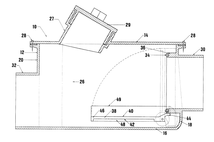
FIGURE 1 is a side elevation view in longitudinal section
of an axial flow backwater valve constructed in accordance with
the teachings of the present invention.
FIGURE 2 is a partially cut away top plan view of the
axial flow backwater valve illustrated in FIGURE 1.
FIGURE 3 is a partially cut away top plan of an angular
flow backwater valve constructed in accordance with the
teachings of the present invention.
FIGURE 4 is a side elevation view in longitudinal section
of the axial flow backwater valve illustrated in FIGURE 3.


DETATT-~n DESCRIPTION OF THE rn~rrKK~ EMBODIMENT


The preferred embodiments, backwater valves generally
identified by reference numeral 10 and 11, will now be
described with reference to FIGURES 1 through 4.

The first embodiment illustrated in FIGURES 1 and 2 is an
axial flow backwater valve, generally identified by reference
numeral 10. Axial flow backwater valve 10 has a liquid
ret~;n;ng body 12 having a top 14, a bottom 16, a first end 18,
a second end 20, opposed sides 22 and 24. sody 12 has an inner
chamber 26. Top 14 of body 12 is secured by removable
fasteners 28 and as such is removable to provide access to
inner chamber 26 for purposes of routine maintenance and
servicing. In addition, a clean out passage 27 with a
removable closure 29 is provided through top 14. A first flow

2114602


conduit 30 extends through first end 18 adjacent top 14 of body
12 and protrudes into inner chamber 26. A second flow conduit
32 extends from inner chamber 26 through second end 20 adjacent
bottom 16 of body 12 and protrudes past second end 20. An
annular seal 34 is positioned on an annular peripheral edge 36
of first flow conduit 30 which protrudes into inner chamber 26.
A plate 38 is pivotally mounted to body 12. Plate 38 has a
wear resistant lubricious first face 40, a second face 42, a
first end 44, a second end 46, and opposed sides 47. Opposed
sides 47 are positioned in close proximity to opposed sides 22
and 24. This prevents hair, toilet paper and other debris from
getting between sides 47 of plate 38 and sides 22 and 24 of
body 12. First end 44 underlies first flow conduit 30. First
face 40 extends past first flow conduit 30 and serves as a
15 spillway for liquid flowing through first flow conduit 30.
First face 40 of plate 38 has sidewalls 49 which extend along
opposed sides 47 and a portion of first end 44 to turn first
face 40 into a flow channel. Referring to FIGURE 1, plate 38
is pivotally movable between a closed position and an open
20 position. In the closed position first face 40 engages annular
seal 34 to prevent a reversal of the liquid flow. In the open
position first face 40 is spaced from annular seal 34 with
first end 44 plate 38 engaging first flow conduit 30. This
serves as stop means for plate 38 in the open position placing
25 first face 40 of plate 38 in a substantially horizontal
position. Plate 38 is maintained in the open position by force
of gravity. A styrofoam float 48 is secured to second face 42
of plate 38 such that plate 38 floats into the closed position
as inner chamber 26 fills with liquid.
The second embodiment illustrated in FIGURES 3 and 4 is
an angular flow backwater valve, generally identified by
reference numeral 11. Angular flow backwater valve is similar
in structure, and in the description which follows like
35 components will be identified by the same reference numerals
by which they were identified in the description of axial flow
backwater valve 10. Angular flow backwater valve 11 includes

2114602


a liquid ret~;n;ng body 12 having a top 14, a bottom 16, a
first end 18, a second end 20, opposed sides 22 and 24. Body
12 has an inner chamber 26. Top 14 of body 12 is secured by
removable fasteners 28 and as such is removable to provide
access to inner chamber 26 for purposes of routine maintenance
and servicing. A first flow conduit 31 extends through top 14
of body 12 and protrudes into inner chamber 26. A second flow
conduit 32 extends from inner chamber 26 through second end 20
adjacent bottom 16 of body 12 and protrudes past second end 20.
An annular seal 34 is positioned on an annular peripheral edge
36 of first flow conduit 31 which protrudes into inner chamber
26. A plate 38 is pivotally mounted to top 14 of body 12.
When top 14 is removed for servicing, plate 38 comes with it.
Plate 38 has a wear resistant lubricious first face 40, a
second face 42, a first end 44, a second end 46, and sides 47.
First end 44 underlies first flow conduit 30. First face 40
extends past first flow conduit 30 and serves as a spillway for
liquid flowing through first flow conduit 30. Sides 47 are
positioned in close proximity to and match the contour of
opposed sides 22 and 24. This prevents hair, toilet paper and
other debris from getting between sides 47 of plate 38 and
sides 22 and 24 of body 12. Referring to FIGURE 4, plate 38
is pivotally movable between a closed position and an open
position. In the closed position first face 40 engages annular
seal 34 to prevent a reversal of the liquid flow. In the open
position first face 40 is spaced from annular seal 34 with
second face 42 of plate 38 engaging a stop 33 which protrudes
from first end 18 of body 12. This serves to position plate
38 at an angle with second end 46 of plate 38 angled toward the
flow path of first flow conduit 31. Plate 38 is maintained in
the open position by force of gravity. A styrofoam float 48
is secured to second face 42 of plate 38 such that plate 38
floats into the closed position as inner chamber 26 fills with
liquid.
It is necessary that first face 40 be made of a lubricious
material in order to ensure that its surface will shed hair,

2114602


toilet paper and other debris. Materials found to be suitable
are polymer plastics used in constructing pipes, such as PVC
plastic and ABS plastic.

It will be apparent to one skilled in the art that
modifications may be made to the illustrated embodiments
without departing from the spirit and the scope of the
invention as hereinafter defined in the Claims. In particular,
there are various alternative floats that could be used in
place of styrofoam float 48. For example, plate 38 could be
constructed out of inherently buoyant materials or with an
underlying air pocket.

Representative Drawing
A single figure which represents the drawing illustrating the invention.
Administrative Status

For a clearer understanding of the status of the application/patent presented on this page, the site Disclaimer , as well as the definitions for Patent , Administrative Status , Maintenance Fee  and Payment History  should be consulted.

Administrative Status

Title Date
Forecasted Issue Date 1997-07-01
(22) Filed 1994-01-31
(41) Open to Public Inspection 1995-08-01
Examination Requested 1996-09-10
(45) Issued 1997-07-01
Expired 2014-01-31

Abandonment History

There is no abandonment history.

Payment History

Fee Type Anniversary Year Due Date Amount Paid Paid Date
Application Fee $0.00 1994-01-31
Maintenance Fee - Application - New Act 2 1996-01-31 $50.00 1996-01-24
Maintenance Fee - Application - New Act 3 1997-01-31 $50.00 1997-01-22
Registration of a document - section 124 $0.00 1997-03-27
Maintenance Fee - Patent - New Act 4 1998-02-02 $50.00 1998-01-26
Maintenance Fee - Patent - New Act 5 1999-02-01 $75.00 1998-11-25
Maintenance Fee - Patent - New Act 6 2000-01-31 $75.00 1999-11-23
Maintenance Fee - Patent - New Act 7 2001-01-31 $75.00 2000-11-24
Maintenance Fee - Patent - New Act 8 2002-01-31 $75.00 2001-11-22
Maintenance Fee - Patent - New Act 9 2003-01-31 $75.00 2003-01-22
Maintenance Fee - Patent - New Act 10 2004-02-02 $100.00 2003-12-15
Maintenance Fee - Patent - New Act 11 2005-01-31 $125.00 2004-11-03
Maintenance Fee - Patent - New Act 12 2006-01-31 $125.00 2005-11-03
Maintenance Fee - Patent - New Act 13 2007-01-31 $125.00 2006-11-06
Maintenance Fee - Patent - New Act 14 2008-01-31 $125.00 2008-01-08
Maintenance Fee - Patent - New Act 15 2009-02-02 $225.00 2008-10-27
Maintenance Fee - Patent - New Act 16 2010-02-01 $225.00 2009-11-26
Maintenance Fee - Patent - New Act 17 2011-01-31 $225.00 2011-01-03
Registration of a document - section 124 $100.00 2011-06-06
Registration of a document - section 124 $100.00 2011-07-28
Maintenance Fee - Patent - New Act 18 2012-01-31 $225.00 2012-01-05
Maintenance Fee - Patent - New Act 19 2013-01-31 $225.00 2013-01-08
Owners on Record

Note: Records showing the ownership history in alphabetical order.

Current Owners on Record
COSARELLA, GABE
MAINLINE BACKFLOW PRODUCTS INC.
Past Owners on Record
1600457 ALBERTA LTD
CHIODO, VITTO
Past Owners that do not appear in the "Owners on Record" listing will appear in other documentation within the application.
Documents

To view selected files, please enter reCAPTCHA code :


To view images, click a link in the Document Description column. To download the documents, select one or more checkboxes in the first column and then click the "Download Selected in PDF format (Zip Archive)" or the "Download Selected as Single PDF" button.

List of published and non-published patent-specific documents on the CPD .

If you have any difficulty accessing content, you can call the Client Service Centre at 1-866-997-1936 or send them an e-mail at CIPO Client Service Centre.


Document
Description 
Date
(yyyy-mm-dd) 
Number of pages   Size of Image (KB) 
Cover Page 1995-10-05 1 14
Abstract 1995-08-01 1 36
Cover Page 1995-10-04 1 14
Description 1995-08-01 7 336
Drawings 1997-05-07 4 69
Claims 1997-05-07 6 202
Abstract 1997-05-07 1 36
Abstract 1995-10-05 1 36
Claims 1995-10-05 4 155
Drawings 1995-10-05 4 95
Description 1995-10-05 7 336
Cover Page 1997-05-07 1 12
Description 1997-05-07 7 328
Representative Drawing 1998-02-24 1 21
Claims 1995-08-01 4 155
Drawings 1995-08-01 4 95
Fees 2003-12-15 1 25
Fees 2003-01-22 1 27
Fees 1998-11-25 1 39
Fees 1998-01-26 1 40
Prosecution Correspondence 1996-09-10 1 41
Office Letter 1996-10-02 1 47
Prosecution Correspondence 1996-09-10 1 40
PCT Correspondence 1997-06-02 1 42
Fees 2004-11-03 1 27
Fees 2005-11-07 1 27
Fees 2006-11-06 1 25
Fees 2008-01-08 2 63
Correspondence 2008-01-08 2 63
Fees 2008-10-27 1 29
Fees 2009-11-26 1 200
Correspondence 2011-03-31 3 133
Correspondence 2011-05-03 1 19
Correspondence 2011-04-28 1 12
Assignment 2011-05-17 4 123
Assignment 2011-06-06 3 97
Correspondence 2011-06-15 1 18
Assignment 2011-07-28 3 71
Fees 1997-01-22 1 32
Fees 1996-01-24 1 38