Note: Descriptions are shown in the official language in which they were submitted.
-
21 1470~
-- 1 --
PA~ o
T~hn~ Al Field of the Invention
This invention pertains to an improved
stringer for a pallet of a type made pre~ i nAn~ y Of
pa~eLL~ard material, such as ~c"LuyaLed paperboard or
multi-ply paper. The ~ _uved stringer exhibits high
compressive strength and good lateral stability.
~r~ n~ of the Inv~ntisn
As made ~L~' ;n~ntly Or co~Lù~dted
P~ ard, multi-ply paper, or similar material,
pallets of the type noted above and methods for their
manufacture are llf1ed in Schmidtke U.S. Patent No.
4,792,325, Q~ n~ck U.S. Patent No. 4,867,074, and Smith
U.S. Patent No. 5,001,991. Typically, such a pallet
comprises elongate stringers and decking members, each
having a desired configuration when viewed endwise.
As disclosed in each of these patents, each
stringer has a generally trapezoidal configuration when
viewed endwise, as a result of a sheet of cuLLuyclted
paperboard, multi-ply paper, or similar material having
been folded to form multiple panels, which define two
Ijy L~ lcal halves of such stringer. ~ ~ .,ve~, in each
stringer, certain panels are secured adhesively to other
panels .
Pallets employing such stringers are available
commercially from Gate Pallet Systems, Inc. of Crown
Point, Indiana, under its PAYLOAD trademark. Efforts to
improve such pallets by improving the stringers used in
such pallets have led to this invention.
other pallets of related interest are
disclosed in Hermitage U.S. Patent No. 2,728,545,
Roberts et ;~1. U . S . Patent No. 3, 683, 822, Melli U. 5 .
Patent No. 4,563,377, and Atterby et al. U.S. Patent No.
4,802,421.
- 2 - ~l 1 4701
summarY of the Invent ion
Thls lnventlon provldes an lmproved stringer for a
pallet made pr~ nAntly of paperboard material, such as
corrugated paperboard or multl-ply paper. The 1 Lov~d
stringer 18 folded from a slngle sheet of such materlal 80 as
to have at least eleven panels. These panels lnclude flve
panels on each slde of a generally vertlcal plane and a lower
panel lntersected by the generally vertlcal plane.
On each slde of the generally vertlcal plane, an
outer panel extends upwardly from the lower panel and an outer
panel extends lnwardly from the upwardly extendlng outer
panel, toward and approxlmately to the generally vertlcal
plane. Also, an lnner panel extends downwardly from the
inwardly extending outer panel toward and approximately to the
lower panel. Moreover, an lnner panel extends upwardly and
outwardly from the downwardly extending inner panel, toward
and approximately to the inwardly extending outer panel, at an
acute angle relative to the downwardly extendlng inner panel.
Furthermore, an inner panel extends inwardly from the upwardly
and outwardly extending inner panel, toward and approximately
to the downwardly extending inner panel.
Preferably, the inwardly extending inner panel on
each side of the generally vertical plane is secured
adhesively to the inwardly extending outer panel on the same
side. Preferably, moreover, the downwardly extendlng inner
panel on each side of the vertical plane is secured adheslvely
to the downwardly extending inner panel on the other side.
23158-1714
_ 3 _ 2t ~4701
Deslrably, the outer panel extendlng upwardly from
the lower panel on each slde of the generally vertlcal plane
extends upwardly and outwardly at an obtuse angle relatlve to
the lower panel. Thus the pallet strlnger ls generally
t rapezoldal when vlewed endwlse .
A plurallty of the lmproved strlngers can be
advantageously comblned wlth a plurallty of decklng members
made pr~n~ln~ntly o paperboard materlal, such as the decklng
members dlsclosed ln the Schmldtke patent noted above, to form
a pr~- ln~ntly paperboard pallet.
Deslrably, when the lmproved strlnger 18 comblned
wlth a decklng member extendlng through allgned apertures ln
the upwardly extendlng outer panels, the downwardly extendlng
lnner panels, and the upwardly and outwardly extendlng panels,
the decklng member 18 secured adheslvely to the lnwardly
extendlng lnner panels. Preferably, each lnwardly extendlng
lnner panel has a tab extendlng lnto at least one of sald
apertures, above the decklng member. More preferably, each
lnwardly extendlng lnner panel has tabs extendlng lnto the
allgned apertures ln the upwardly extendlng outer panel and
the downwardly extendlng lnner panel, above the decklng
membe r .
A plurality of the lmproved strlngers can be
alternatlvely comblned with an upper sheet of paperboard
materlal or wlth upper and lower sheets o~ paperboard
materlal, as dlsclosed ln a commonly owned, ~'~n~ n Patent
2, 094, 895 .
e -~
~ 23158-1714
- 3a - 2~ 1 4701
Whether employlng such decklng members, such as an
upper sheet, or such upper and lower sheets, a pre~m1n~ntly
paperboard pallet employing the lmproved strlngers exhlblts
hlgh compresslve strength and good lateral stablllty.
These and other objects, features, and advantages of
thls invent lon are evldent f rom the
23158-1714
21 1470l
-- 4 --
following description of a preferred ~ _'ir ~ of this
invention with reference to the Al _ ylng drawings.
Brief DescriDtion Or the Drawin~:
Figure 1 i5 a pel,,ye,~ive view of a
pr~d~ inAntly paperboard pallet employing three improved
stringers according to this invention together with an
upper sheet and a lower sheet. Optional reinforcing
strap6 are shown in dashed lines.
Figure 2 is a pe~Jye~;Live view of a
p~ nAntly p~ l.oArd pallet employing three i _L~v~:d
stringers according to this invention together with
three pairs Or decking members.
Figure 3 is an end view of an i uv~d
atringer according to this invention, as used in the
pallet of Figure 2.
Figure 4 is a plan view Or a blank of
~LL~ ed pAr~-l OArd, as used to make the ~Ip~LLuLe:d
stringers of the pallet of Figure 2.
Figure 5 is an enlarged, frag~entary detail of
one half of an apertured stringer n~ade from the blank Or
Figure 4.
Figure 6 is an enlarged, fragmentary detail of
one edge of the blank, as shown in Figure 4.
DetAiled Description Q Preferred r ~
As shown in the drawings, an improved stringer
10 constituting a preferred: ' :'ir-nt of this invention
is useful in making a yI~ nAntly paperboard pallet
exhibiting high :assive strength and good lateral
stabil ity .
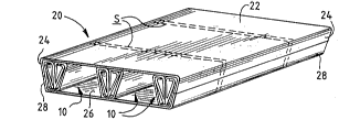
Thus, in one such pallet 20 shown in Figure 1,
three such stringers 10 are combined with an upper sheet
22 having two outer flaps 24 folded downwardly and with
a lower sheet 26 having two outer flaps 28 folded
upwardly. The upper and lower sheets 2a, 26, snd the
outer flaps 24, 28, are secured adhesively to the
21 14701
-- 5 --
stringers 10. Optional reinforcing straps S are shown
in dashed lines. Except for the stringers 10, the
pallet 20 is similar to a pallet illustrated and
described in the ~opc~n~1inq application noted above, the
fi; R~lORllre of which is in~uL~o~ated herein by reference.
Also, in another such pallet 30 shown in
Figure 2, three such stringers 10 are combined with
three pairs of decking members 32 extending through
~eLLuLas 34 in the stringers 10. The decking me~bers
32 are secured adhesively to the stringers 10 at margins
o~ the aperl uL.ss 34. Each decking member 32 is folded
from a single sheet of ~ rl~oArd material, such as the
material used for the stringers 10, 80 as to have
multiple panels, some of which panels are secured
adhesively to other panels of such decking member 32.
Each decking member 32 is similar to the decking members
r1; Rr~ ,RDd in the Schmidtke patent noted above. Except
for the stringers 10, the pallet 30 ia~ similar to the
pallets disclosed in the Q-1~Rn~Ck and Schmidtke patents
noted above, the di6closures of which patents are
inCoL~uLl,ted herein by reference.
The i ~uved stringer 10 is folded from a
single sheet of double wall, cuLLu~.lted pAr~rho~r
which may be tape-reinforced or fiber-reinforced.
Single wall, uuLLuyated paperboard or multi-ply paper
may be alternatively used.
Herein, directional terms including "upper",
"lower", "vertical", "horizontal", "upwardly",
"downwardly", "inwardly", and "outwardly" refer to the
~ uvl:d stringer 10 and the pallets 20, 30, in
preferred orientations, in which they are shown. The
,v~d stringer 10 and the pallets 20, 30, would be
l~lso useful in inverted orientations. Usage of such
directional terms is not intended to restrict this
invention to the preferred orientation.
~1 l4701
-- 6 --
As shown in Figure 3, the i _ vv~d 6tringer 10
i5 folded so as to have eleven panels, namely five
panels on each ~ide of an ~-gln~ry, generally vertical
plane P and a generally horizontal, lower panel 40,
which i8 int~:l,,e- ~ed by the plane ~. Also, as shown in
Figure 3, the lower panel 40 is bisected by the plane _.
Preferably, as shown, the ~ ~ ~,v~d ~;tringer 10 is folded
along parallel folding lines extending in a ~lli,
direction relative to flutes of the single sheet o~
cvL L .~ ted paperboard .
On each side of the plane _, an outer panel 42
extends upwardly and outwardly from the lower panel 40,
at an obtuse angle relative to the lower panel 40.
Also, an outer panel 44 extends inwardly from the
upwardly extending outer panel 42, toward and
approximately to the plane _. Further, an inner panel
46 extends downwardly from the inwardly extending outer
panel 44, toward and approximately to the lower panel
40. ~ Levv~r, an inner panel 48 extends upwardly and
outwardly from the downwardly extending inner panel 46,
toward and approximately to the inwardly extending outer
panel 44, at an acute angle relative to the downwardly
extending inner panel 46. Fur~h~ e, an inner panel
50 extends inwardly from the upwardly and outwardly
extending inner panel 48, toward and approximately to
the downwardly extending inner panel 4 6 .
As shown in Figure 3, the downwardly extending
inner panel 46 on each 6ide of the plane _ is ~ecured
adhesively to the downwardly extending inner panel 46 on
the opposite ~ide, in a wide region 52 between the
panels 46. Also, the inwardly extending inner panel 50
on each side of the plane _ is secured adhesively to the
inwardly extending outer panel 44 on the same side, in a
wide region 54 between the panel 50 and the panel 44.
Moreover, the upwardly and outwardly extending inner
-
-
21 1 4701
-- 7 --
panel 48 on each side of the plane ~ is secured
adhesively to the upwardly and outwardly extending outer
panel 42 on the same side, in a region 56 near the
inwardly eYtending outer panel 44 on the same side.
Fur~h~- e, on each side of the plane P, the adhesive
applied in the region 54 and the adhesive applied in the
region 56 may be contiguously applied.
Preferably, the adhesive applied in the
regions 52, 54, 56, is a so-called "cold melt" or "cold
set" adhesive, such as Code No. 3715 or Code No. 3715B,
both of which are available u ially from H. B.
Fuller Co. of Palatine, Tll~nn;~:.
In the pallet 30, which is shown in Figure 2,
the apeLLUL~:S 34 are located 80 as to permit the decking
members 32 to pass closely beneath the inwardly
extending inner panels 50 of the respective stringers
10. Preferably, the upper 6urfaces of the decking
members 32 are secured adhesively to those panels 50 of
the respective stringers, by one of the adhesives noted
2 0 in the preceding paragraph .
As shown in Figure 3, because each of the
outer panels 42 extend upwardly and outwardly at an
obtuse angle relative to the lower panel 40, the
1 _ uv~d stringer 10 is generally trapezoidal, when
viewed endwise. Moreover, the i __v~"=d stringer 10 is
generally symmetrical on opposite ~;ides of the plane P,
when viewed endwise.
As illustrated in Figure 4, a representative
stringer 10 of the pallet 30 is made by die-cutting and
folding, along folding lines indicated by broken lines
in Figure 4, a UC LL ~Iyated p~r~rhOArd blank 60 and by
adhesively securing certain panels of the blank 60 to
other panels of the blank 60, as described previously.
On each side of the plane P, the inwardly ~Yt~nllin~
inner panel 48 has two oppositely extending tabs
_
21 1 470i
-- 8 --
associated with the aligned apertures 34 to receive each
decking member 32, namely a tab 62 ~Yt~n~lin~ into the
dpéLLuL~: 34 in the upwardly and outwardly ~Yt-n~n~
outer panel 42 on the same side and a tab 64 extending
into the aperture 34 in the downwardly extending inner
panel 46 on the same side. MoLe~ve~ the upper surfaces
of the decking members 32 are secured adhesively to the
tabs 62, 64, as well as to the aforesaid panels 48 by
one of the adhesives noted previously. I'he tabs 62, 64,
provide larger areas for adhesive se-uL~ ~ of the
decking members 3 2 .
Each stringer 10 of the pallet 20 is similar
to each stringer 10 of the pallet 30, as described
above, except that the apertures 34 and the tabs 62, 64,
may be optionally omitted. In the pallet 20, aa shown
in Figure 1, the ~eLLuLès 34 and the tabs 62, 64, have
been omitted.
With or without the apeL Lules 34 and the tabs
62, 64, the ~ , Jved stringer 10 compares favorably in
compressive ~-LLe~yL~I and lateral stability but requires
less material as compared to a stringer having similar
overall dimensions and having eleven panels folded and
secured adhesively as disclosed in the Qu~Sn;~k patent
noted above.
Irhe 1 ~ uved gtringer 10 can be additionally
stabilized with tubular reinforcing pieces, as disclosed
in Smith U.S. Patent No. 5,001,991.
Various modifications may be made in the
preferred ~ r L described above without departing
from the scope and spirit of this invention.