Note: Descriptions are shown in the official language in which they were submitted.
wo 93/03311 pcr/lEg2/oooo4
3 3 ~
'ITemperature control appara$us and a central unit
for temperature control apparatus"
Field of the invention
The present invent;on relates to mult;-~one temp~ture control
5 apparatus, and in particular, though not lim;ted to multi-zone
space temperature control apparatus for cooling and/or heating
respective zones of a bu;lding or the like independently of each
other. The invention also relates to a central un;t for
supplying B heat transfer medium to at least one remote unit of
10 temperature control apparatus. Further, the invention relates to
a remote unit for rece;ving a heat t~ansfer medium from a central
unit for controllin~ temperature. The invention also relates to
~emperatur* control apparatus which comprises at least one
central unit and one remote unit. The inYention also relat~s to
a method for controlling the energy output of the central unit.
~b~
Temperature control apparatus for space heating andlor cooling
for controlling the temperature in one or more ~ones of a
building is known~ One type of temperature control apparatus
comprises a central unit which comprises a refrigeration circuit,
which may be reversible and operated in a chilling mode and a
heat pump ~ode for delivering cooling and/or heating to one or
more remote units mounted in the zones of a building for
controlling tt)e temperature of one or more zones of the building.
However, in generall such apparatus are restricted to e;ther
supplying cooling or heating at any given time. In other words,
the remote units would normally all be deliYering heating or
cooling at the same time. It is not possible, in general, to
provide a plurality of remote units connected to a single central
~0 un;t where the remote units can simultaneously, independently of
each other supply heating and cooling to control the temperature
of respective zones.
A further problem with such apparatus for heating and/or cool;ng
WO 93~03311 P(~/IE92~00004
't~ .Ll~ '8
a bu;lding which compr;ses a central unit for supplyin~ heating
and/or sooling to ~ remote uni$ or units is that such apparatus
tend to be relatively inefficient in use. A particular problem
with sush apparatus is that, in general, the central ~nit
gener~tes heating or cooling at a rate which is,largely
independent of the rate at which the remote unit or units is or
are demanding hea~ing or oooling. This it w;ll be apprec;ated
leads to eonsiderable loss and wastage of heat or cooling energy
whioh is undesirable~
There is therefore a need for multi-zone ~emperature control
appa~atus for co~trolling the temperature in one or more zones.
There is also a need for temperature con~rol apparatus for
eontrolling the temperature of a single zone. Further, there is
a need for a central unit for supplying a heat transfer medium to
one or more remote units of such apparatus, and there is also a
need for a remote unit for such apparatus. There is also a need
for a ~ethod for controlling the energy output of the central
unit.
The present ;nvent;on is directed towards proYiding such a multi~
zone temperature eontrol apparatus, such temperature control
~pparatus, such a central unit and a re~ote unit and a method.
Throughout th;s specificat;on, where reference is made to heat
being transferred between a central unit and a remote unlt, it is
to be understood that the heat may be transferred both ways or
one way only between the central unit and remote unit. For
example, heat is transferred to a remote unit when a central unit
is supplying heating energy to the remo~e unit, and hea~ is
transferred from the remote unit to the central unit when the
central unit is supplying cooling energy to the remote unit~ In
other words, when a central unit is operating in a chilling mode,
cooling energy is supplied to a remote un;t, and accordingly,
heat is being transferred from the remote unit to the central
unit. On the other hand, when a central unit is operating in a
... , . . . . . ~ ~ ... . . . .
WO 93/03311 PCI'/IE92/0000'1
~ 9 ~3 ~
heating mode for supplying heating to the remote unit, heat is
being transferred from the central unit to the remote unit. The
oentral unit may be prov;ded to operate in a ch;lling mode only,
or in a heating mode only, or both. Further, reference to a
refrigeration eircuit is to be understood ~o me~'~ eference ~o
any such circu;t which may operate in a chilling mode for
providing coolin~ or in a heating mode for providing heating or
in both modes.
~h~
One object of the invention is to provide multi-zone temperature
control apparatus which permits independent control of the
temperature of different zones, and further, permits heating of
one ~one while at the same time another zone is being cooled. It
is also an object of the invention to provide suoh multi-zone
heat oontrol apparatus which operates relatively effieientlyO and
which can be installed at relatively low cost and with minimum
inconven;ence.
Another object of the invention is to provide temperature control
apparatus for controlling the temperature of at least one 20ne
20 whioh operates relatively efficiently, and which may be installed
at relatively low cost with minimum inconvenience.
.
- - A further object of the invention is to provide a central unit
for sueh tempe~ature eontrol apparatus or multi-zone kemperature
control apparatus which operates relatively effic;ently, and
whieh can be installed at a~relatively low cost and with minimum
inconvenience. It is also an object of the invention to provide
such a eentral unit ;n which the energy output de7ivered by the
central unit can be matched to the demand for energy by a remote
or remote unitO A further object of the invention is to provide
a remote unit for such temperature control apparatus or multi-
zone temperature control apparatus which operates relatively
efficiently, and wh;ch can be installed at relatively low cost
and with minimum inconvenience.
W0 93/03311 P(~r/lE92/00004
3 8
Another object of the invention ;s to provide a method for
controlling the energy output of a oentral unit of temperature
control apparatus so ~hat the energy output can be matched ~o the
demand for energy from a remote or remote un;ts of the
temperature control appara~us. ,' -
Su~m3¢y_sf_the inventionAceording to the invention there 7s provided a central unit for
supplying a heat transfer medium to at least one remote unit of
temperature control apparatus for transferring heat between the
central unit ~nd the remote uni~, the oentral unit comprising a
refrigeration circuit having a refrigerant medium therein, the
retrigeration c;rcu;t compr;sing a master heat exchanger for -:exc:hanging heat with the refrigerant medium, and a main heat
ext:hanger for exchanging heat betwleen the refri~erant me!dium and
th! heat transfer medium, a compressor means for compressins the
refrigerant medium, and an expansion means for expanding the
refrigerant medium, return tempera~ure monitoring ~eans for
monitor;ng the return te~perature of the heat transfer n~edium
returning to the main heat exchan~er, differentlating m~ans for
20 determiniflg the rate of change of the return temperature of the
heat transfer Ined;um with respect to timel first control means
responsive to the differlentiating means for controlling the
energy OUtpllt of the refrlgeration circuit ln response to ~he
rate of change of the return temperature of the heat transfer
25 medium with respect to time.
By proYidlng a control means which ;s responsive to the
differentiating means for controlling the energy output of the
refrigeratioll circuit in response to the rate of change of thé
return temperature of the heat transfer medillm with resp~ect to
30 time, the energy output of the cen~ral unit can be substlantially
mat:ched to the demand for energy being placed on the central
un;t, by one or more remote units. This leads to a relatively
eff icient device and minimises energy wastageO
W O ~3/033ll PCTJIE92/000~4
338
Preferably, the f;rst control means varies the energy output of
the refrigeration circuit; in response to a change in the rate of
change of the return temperature of the heat ~ransfer medium with
reslpects to t;me. Th;s perm;ts relatively accurate matching of
5 the energy output of the central unit to the d ~ -d for energy.
Adv,antageously, the f;rst control means is responsive to the rate
of ehange of the return tempera~ure of the heat transfer medium
witlh respect to time moving from one predetermined range of rates
of change o~ return temperature to another range. By haYing the
first control means responsive to th~ rate of ehange of the
return temperature moving from one predetermined range to
another, an apparatus which operates relative7y effic;ently is
provided and frequent variations in the operation of the central
unit are avoided.
In one embodiment of the invention the first control means is
respons;Ye to the rate of change of the return temperature of the
heat transfer ~ed;u~ with respect to time reaching a
predetermined value. ~y having the first control means
responsive to the rate of change of the return temperature of the
heat transfer medium with respect to time reaehing a
preldeter~ined value, particularly advantageous form of t:he
;nvention is prov;ded. The central unit according to the
invention operates~particularly efficîently-and frequent
variations in the ope~ation of the central unit are avo~ided.
In one embodiment of the ;nvention the f~rst control means
comprises compressor cont~ol means for controllin~ the c:ompressor
means ~or varying the energy output of the refr;geratiorl circuit.
By controlling the compressor means of the refri~eration circuit
relatively effeGtive control of the central unit is pro~ided and
matching of the energy output of the central to demand is
relatively eff;ciently obtained.
Preferably, the compressor control means comprises mean!i for
WO 93/0331 I c " PCI`/11E~2/00~0'1
controlling the m~rk/space ratio of a power supply beins
delivered to the compressor means. By oontrolling the mark/space
ratio of the power supply being del;vered to the co~pressor
controller relatively eff;c;ent and effective control of the
refrigeration circuit is achieved. ,~ _
Advantayeously, the coMpressor control means varies the
mark~space ratio of the power supply to the compressor means
inversely to the rate of ehange of the return temperature with
respect to time. This provides relatively efficient and accurate
means of controlling the oentral unit.
In one embodiment of the invention a circulating pump means f~r
ciroulating the heat transfer medium ~hrough the main heat
exchanger is provided, the first control means comprising pump
control means for controlling the ~elivery of the pump means, the
pump control means being responsive to the differentiating means
for contrclling the delivery of the pump means in respon!se to the
rate of changs of the return temperature of the heat transfer
mediu~ to the ~ain heat exchanger with respect to time.
Controlling the pump means further facilitates eontrol of the
20 central unit for matching the energy sutput of the central un;t
to the demand..
1n one embodiment of the invent;on the pump control means varies
the delivery of the pump means inversely to the rate of change of
the return temperature w;th respect to t;me. This provides
relatively effieient means of controlling the circulat;on of the
heat transfer medium which in turn facilitates ma~ching the
energy output from the cental uni~ to the demand.
In one embodiment of the invention the first control means is
responsive to the return temperature of the heat transfer medium~
By h~ving the first control means also responsive to the return
temperature of the heat transfer medium, matching of the energy
output of the central to the demand from the remote unit or units
WO g3/03311 ~ 9 3 8 pcr/IE92/ol)
is further facili~ated.
In one embodlment of the ;nvent;on the first control means is
responsive to the return temperature of the heat transfer medium
moving from one predetermined r~nge o~ return t~eratures to
S another range. This provides a relatively effic;ent means of
controlling the pump meanst and frequent variations in the
operation of the central unit are avoided.
In one embodiment of the invention the compressor control means
varies the mark/space ratio of the power supply to the compressor
means proportionately to the t~mperature difference between the
return temperature of the heat transfer medium and the flow
temperature o~ the heat transfer medium flowing from the main
heat exchan~er. This fur~her facilitates matching of the energy
output of the central ~o ~he demand by the remote unit or uni~s.
,~
In a further embodiment of the in~ention the pump eontrol means
varies the delivery of the pump me~ans proportionately to ~he
d;fference between the re~urn temperature of the heat transfer
medium and the flow temperature of the heat transfer medium
flowing from the main heat exchanger. This provides a relatively
efficient control means for the pump means.
Xn one embodiment o~ the i mention the-refrige~ation circuit is
reversible and is operable in a chilling ~ode and a heat pump
mode, and means for reversing operation of the refrigeration
circuit bet~een the two modes is provided. The advantage of
providing a reversible circuit is that a single central unit may
be operated in a chilling mode for providing cooling to the
remote unit and in a heat pump mode for pnoviding heat;ng to the
remote unit.
Advantageously, the compressor means is a scroll compressor. It
has been found that a scroll compressor is a relatively efficient
compressor and is particularly suitable for control for varying
wo s3/033~ 3 ~ P~ s2/00~04
the energy output of the ~cfrigeration circuit.
Preferably, the heat transfer medium is water. Where the heat
transfer medium is water a relatively low cost and ef~icient
apparatus is provided, and ~urthermore, the app~r~atus is
environmentally friendly and does not provide a health hazard.
Additionally, the invention proYides a remote unit for receiving
a heat transfer medium from a cen~ral uni~ of temperature control
apparatus for transfernirlg heat between the central unit and the
remote unit, the remot2 unit compris;ng a sec~ndary heat
exchanger for exchanging heat wi~h the heat transfer medium, a
booster heat delivery means, and a heat transfer means for
transferring heat to or from the secondary hea~ exchan~er and the
booster heat delivery means, air temp~rature monitoring means for
~onitoring the return temperature of air ~o the remote unit, and
seeond control means responsive to the air temperature monitoring
means for controlling the heat transfer means and for delivering
a signal to the first control means for activating the central
unit. The remote unit provides a relatively eff;cient apparatus
for providing heating and/or cooling to a zone, and by virtue of
the fact that a signal is transmitted from the remote unit to the
eentral unit, the central unit reacts quicker than if the central
unit were reliant solely on the flow and return temperatures of
the heat transfer medium.
Further, the invention provides temperature eontrol apparatus
comprising a central unit according to the inventi~n and a remote
unit al~o according to the invention, the remote unit being
connected to the central unit by a circulating eircuit for
circulating a heat trans~er medîum between the central unit and
the remote unit. The temperature control apparatus aecording to
the ;nvention is a particularly efficient apparatus.
Further the invention provides multi-zone temperature control
apparatus comprising a plurality of remote units, one remote unit
W O 93J03311 PCT/IE92J00004
3 ~'
being provided for each zone, a cen~ral unit for supplying a heat
transfer medium to the remote units for transferring heat between
the central unit and the respective remote units for controlling
temperature of the zones, each central unit comprising a main
heat exchanger for exchanging heat with the he~t~Eransfer medium,
and first control means for controlling the central unit, each
remote unit comprising a secondary heat exchanger for exchanging
heat with the heat transfer medium, a heat transfer means for
transferring heat between the secondary heat exchanger and the
zone, air temperature monitoring means for monitoring the
temperature o~ air in the zone, and second control means
responsive to the air temperature monitoring means for
controlling the heat transfer means and for deliYering a signal
to the first control means for activating the central unlt in
response to a change in temperature of the air, the apparatus
further compris;ny a plurality of circulating circuits for
communicating the secondary heat exchan~ers of respec~ive remo~e
units w;th the main heat exchanger of the central unit for
circulating the heat transfer medium between the main hea~
exchanger and the respective secondary heat exchan~ers,
circulating means bein~ provided in respective circulating
c;rcuits far circulating the heat transfer medium.
Th~ advantage of the multi-zone temperature control apparat~s
according to the inv~ntion ~s that it permits the temperature ;n
different zones to be controlled at different levels. It also
permits independent control of the temperature in the zones
relative to each other, and under certain condition, enables some
zones to be heated while at the same time others are being
cooled.
In one embodiment of the invention each circulating ~eans i5
responsive to the first control means. The advantage of having
the circulating means responsive to the first control means is
that relatively efficient control of the apparatus is achieved.
w o 93tO3311 pc~r/lEs2/oooo4
3 8
In another embodiment o~ the invention the heat transfer medillm
is water. This pr~v;des a relatively low cost and eff;c;ent
apparatus which is also environmentally friendly and does not
present a health hazard, and furthermore may be relatively easily
5 ;nstal led. , ~
In another embodiment of the invent;on the circulatin~ c;rcuits
are conneoted to the main heat exchanger independently of each
other. This permits opera~ion of the remote units independently
o~ each other.
10 In one embodiment of the invention each remote unit
comprises a booster heat delivery means, the heat transfer means
co-operating with the booster heat delivery means for
transferring heat between the boos~er hea~ delivery means and the
zoneO This permits some of the remote units to provide heating
at the same time others of the remote units are providing
cooling. For example, where the c:entr~l unit provides heating or
cooling and the booster heat delivery means provides the
alternative form of energy, ~he central unit may thus supply the
remote units requiring the type of energy being supplied by the
20 central unit, while the other remote units can supply the
alternative form of energy by means of the booster heat del;very
- means. ~Additionally, the booster heat delivery means may supply
additional energy i~ the central unit is unable to meet the
demand.
Preferably, the booster heat delivery means is responsive to the
second control means. This provides efficient control of the
apparatus.
In ansther embodiment of the invention each booster heat del~very
~eans comprises a heat source. This permits th~ remote units to
provide additional heat from the boos~er heat delivery means in
the event that the central unit is unable to meet the demand for
heating by the remote unit, either as a result of lack of
. . .
WO 93/03311 pcr/lEg2/oooo4
3 3 ~
11
capacity, or the central unit bein~ in a chilling mode supplying
cooling to another remote unit.
Advantageously, each booster heat delivery means is pnovided by
an electrically powered heat source. This provi~es a relatively
S efficient and easily installed remote unit.
Preferably, each secondary heat exchanger is provided by a coil
heat exchanger. This leads to a relat;vely efficient remote
unitO
Advanta~eously, each heat transfer means oomprises a fan. This
provides a relatively eff icient remote unit.
P~eferably, the fan is elec~rically power~d. This provides a
relat,vely efficient remote unit.
Advantageously, each circulating means comprises a circulating
pump. This provides a relatively efficient apparatus.
15 Preferably, each circulating pump is an electrically powered
variable speed circulating pump. This proYides a relatively
efficient apparatus.
In one embodiment of the invèntion the air temperature monitoring
means are mounted in the respective remote units for ~onitoring
ZO the ~eturn air temperature of air returning to the respective
remote units. Th;s provides a relatively efficient remote uni~
with a relatively quick response time.
In one embodiment of the invention the central unit comprises a
refrigeration c;rcu;t having a refr;gerant medium therein and
comprising the main heat exchanger for exchanging heat between
the refrigerant medium and the heat transfer medium, a master
heat exchanger for exchanging heat with the refrigerant medium, a
compressor means for compressing the refrigerant medium and an
WO 93/03311 P~/IE92~00004
9 3 8
î2
expansion ~eans for expanding the refrigerant mediu~, the
refrigeration c;rcuit being responsi~e to the first control
means. This provides a relatively efficient construction and
operation of apparatus.
, ~
5 In another e~bodiment of the invention the refrigerat;on oircuit
is reversible, and means for reversing the refrigeration circuit
is proY;ded. The advantage of providing a reversible :~
refrigerat;on c;rcuit is that a single central unit ~ay provide
cooling and heating energy.
Preferably, the multi-zone temperature oontrol apparatus
comprises a central unit according ~o the invention. The
advantage of prov;ding the multi-zone temperature apparatus with
such a central unit is tha~ the energy output of the central unit
can be matched to the demand of the remote units, and an
15 effioient apparatus is provided"
In one embodiment of the invention flow temperature monitoring
means for monitoring the flow temperature of ~he heat transfer
medium from the main heat exchanger ;s provided in each
circulating oircuit~
In a further embodiment o~ the invention flow measuring means is
provided in ~ach circulating circuit, the flow temperature
monitorin~ means and flow measuring ~eans being connected to the
first control means for enabling computation of the energy
delivered to the secondary heat exchangers of the respective
remote units. The advantage of providing flow measuring means in
the eirculating circuits is that it provides for computation o~
the energy being supplied to the respective remote units.
The inven~ion also provides a method for controlling the energy
output of a central unit of temperature control apparatus,
wherein the central unit is of the type which supplies a heat
transfer medium to at least one remote unit of the temperature
WO 93/03311 PCI'/IE92/00004
3 8
control apparatus f~r transferring heat between the central unit
and the remotc unitl and the central unit comprises a
refrigeration circu;t hav;ng a refrigerant med;um therein, the
refrigeration circuit comprising a master heat exchanger for
S exehanging heat with the refrigerant medium, a~_a main heat :~
exchanger for exchanging heat between the refrigerant medium and
the heat transfer medium, a compressor means for compressing the
reFrigerant medium, and an expansion means for expanding the
refrigerant medium, the method comprising the steps of
determining the rate of change of the return temperature of the
heat transfer medium returning to the main hea~ exch~nger with
re~speet to time, and controlling the energy output of tlle
refrigeration circuit irl response to the rate of change of the
return temperature of the heat transfer medium. The advantage of
the method is that it permits the energy ou~put of the cen~ral
unit to be substantially matched to the demand from a remote or
remote units.
In one embodiment of the invention ~he method comprises the step
of varying the energy output of the refrigeration circuit in
response to a ehange in the rate of change of the retur~l
temperature of the heat transfer medium with respect ~o time.
In another embodilnent of the imention the energy output of the
refrigerat;on circuit is varied ;n response to the rate of chanye
of the return temperature of the heat transfer medium with
25 respect to time moving ~From one predetermined range of rates of
change of return temperature.to another range.
In one embodiment of the invention the energy output of the -
refrigeration circuit is var;ed in response to the rate of change
of the return temperature of the heat transfer medium with
30 respect to time reaching a predetermined value.
Preferably, the method comprises the step of controlling the
compressor means for varying the energy output of the
wo 93Jo331 I PCr/IE92/1)0004
' 8
14
refrigeration circuit.
In another e~bodiment of the invention the method oQmprises the
step of controlling the mark/space ratio o~ a power supply being -;
delivered to the compressor means. ~ ~
Advantageously, the method colnprises the step of varying the ::
mark/space ratio of the power supply to the compressor means
inversely to the r3te of change of the return temp~rature with
res ect to time
P
Advantageously, the method comprlses the step of varying the
energy output of the refrigeration oircuit in response to a
change in the return temperature of the heat transfer med;um.
Preferably, the method comprises the step of varying the energy
output nf the refrigeration circuit in response to the return
temperature of the heat transfer medium moving from one
predetermined range of return ternperature to another range.
In one embodiment o~ the invention the method comprises the step
of varying the mark/space ratio o~ the power supply to the
compressor means proportionately to the temperature d;fference
be~een the return telnperature of the he~t transfer medium and
the flow temperatllre of the heat transfer medium flowing ~rom the
main heat exchanger ~
In a further embodiment of the invention the method further
comprises the steps of varyiny the rate of circulat;on of the
heat transfer medium through the main heat exchan~er in response
to the rate of change of the return temperature of the heat
transfer medium to the main heat exehanger with respect to time.
~3~ . .. .
The adYanta~es of the invention are many. A particularly
important advantage of the mult;-zone temperature control
W O 93/0331l PCT/IE92/000~4
3 3 8
apparatus ;s that it permits independent control of the
temperature ~f different ~ones. Furthermore, it permits heating
of one or ~ore zones while at the sa~e t~me another or others of
the zones are being eooled. Another advantage of the invention
is that it permits the energy output of the cen~al unit to be
substantially matched to the demand of the remote or remote
un;ts. Furthermore, where a control unit is provided in
temperature control apparatus with only one remote unit, the
energy output of the central unit can be substantially matched t9
the demand of the remote uni~. Further, the invention provides a
multi-zone temperature control apparatus which is relatively
effi~ient to manufaeture, to install and to use. The apparatus
is also relatively inexpensive and robust. Where ~he heat
transfer medium is provided by water, a particularly
environmentally friendly apparatus is provided, and furthermore,
the apparatus does not present a health hazard and addi~ionally,
the appa~atus can be readily easily installed in a building or
other location. The central unit, the remote unit and the
temperature control apparatus are also relatively efficient to
manufacture, install and use, and can be provided a~ a relatively
low cost4 Installation of the multi-zone temperature control
apparatus and the temperature eontrol apparatus as well as the
central unit and remote unit can be carried out with minimum
inconvenience.
2~ The method according to the invention for controlling the energy
output of the central is a particularly effeetive and effic;ent
method for controlling such a central unit.
The ;nvention will be more clearly understood from the following
description sf some preferred non-limiting embodiments thereof
given by way of example only with reference to the accompanying
drawings .
Br ef desc~iPtion~of the drawi~gs
Fig. 1 is a schematic diagram of temperature control
WO 93/03311 pcr/lEs2/oooo4
? 8
16
apparatus aecording to the inYen~ion for space heating
and/or cooling of a building for controlling the
temperature of a zone of the building,
Fig. 2 is a schematic diagram of portion o~ the temperature
S control apparatus of Fig. 1 illustrated ;n a different mode
of operation,
Fig. 3 ~a~ and (b) is a f low ehart of a computer progrannne
for controlling a remote unit of the apparatus of Fig, 1,
Fig. 4 is a flow chart of a computer prograa~ne for
controlling a central unit of the apparatus of Fige 1
Fig. ~ is a flow chart of a sub-routine of the computer
progran~ne o~ Fig. 4,
Fig. 6 is a flow chart of another sub~routine o~ the -~
computer programne of Fig. 4, -
Fig. 7 is a schematic diagram of multi-zone temperature
control apparatus according to the ;nYention for space
heating and/or cooling of a plurality af zones in a :~
buildin~, and ~ ~
F;g. 8 is a perspective schematic diagram olF the apparatus
of Fig. 7 installed in a building.
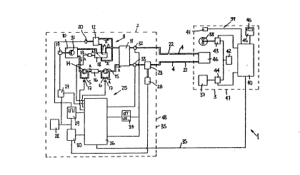
Referning to the drawings and initially to Figs. 1 to 6 there is
illustrated temperature eontrol apparatus accord;ng to the
invention indicated generally by the reference numeral 1 for
25 spaee heating and/or cooling a single zone in a building. The
heat control apparatus 1 comprises a central ~nit 2 also
aceording to the invention for supplyiny a heat transfer med;um,
namely, water to a remote unit 3, also according to the
wo 93/03311 PCT/IE92/000~4
3 8
1~
invention, for mounting in the zone of the building for heating
and/or cooling the zone. A oirculating circuit 4 connects the
cen~ral unit 2 ~nd ~he remote unit 3 fo~ circulating the heat
transfer med;um between the units 2 and 3 as will be described
belsw. The central unit 2 comprjses a reversib~_refri~eration
circuit 8 which is operable in a chill;ng mode for xupplying
cooling energy and in a heat pump mode for supplying heating
energy from the central 2 to the remote unit 3~ A refrigerant
medium, namely, freon gas is provided in ~he refrigeration
eircuit 8~ The refrigeration c;rcuit 8 compr;ses a master heat
exchanger 10 which in this case is provided by a fan assisted
coil heat exchanger for exehanging heat between the refrigerant
medium and the ambient air adjacent the central unit 2. A ~ain
heat exchanger 11 in the refrigeration circuit 8 exchanges heat
between the refrigerant medium and the heat transfer medium in
the eirculatlng circuit 4. The main heat exchanger 11 is
provided by a plate heat exchanger. A compressor means, namely,
a compressor 12t in this ease a scroll compressor compresses the
refrigerant medium. An expans;on means, namely, a pair of
expansion valves 14 and 1~ are connected between the master heat
exchanger 10 and the main heat exchan~er 11 for expanding the
refrigerant medium. A rece;ver 16 between the expansion valve 14
and l5 receives and buff ers t~e expanded refrigerant mediumO
Bypass valves S and 6 connected in parallel with the expansion
valves 14 and:15 are alternately opened so that one of the
expansion valves 14 and 15 is bypassed and the other i5
operational depending on the mode of operation of the
refr;gerat~on eircult 8. In a chill;ng mode the refrigerant
medium is expanded through the expansion valve 14, while in a
heat pump mode the refrigerant medium is expanded through the~
expansion valve 15. Reversing means for reversing the
refrigeration eircuit 8 to operate in a chilling mode and in a
heat pump mode comprises a reversing valve 18 which connects the
master heat exchanger 10l the main heat exchanger 11 and the
eompressor 17. When the refrigeratiQn circ~it 8 is to operate in
the chilling mode the revers;ng valve 18 is configured as
WO 93/03311 !PCI~/IE92/00004
18
illustrated in Fig. 1 and the flow of refrigerant medium through
the refrigeration circuit 8 is in the di~ection of arrows A. In
this configuration the master heat exehanger 10 acts as a
condenser, and the main heat exchanger 11 acts as an evaporator,
thus remoYing hea~ from the heat ~rans~er mediu~-in ~he main heat
exchanger 11 for delivering cooling to the remote unlt 3~ When
the refrigeration circuit 8 is operating in the heat pump mode
the reversing valve 18 is configured as illustra~ed in FigO 2 and
flow o~ the refri~erant medium throu~h the refrigeration circuit
B is in the direction of ~he arrows ~. In ~he hea~ pump mode
configuration, the master heat exchanger 10 acts as a evaporator
and the main heat exchanger 11 acts as a condenser, thus
transferring heat into the heat transfer medium circulating
through the main heat exchanger 11, thus delivering heating to
the remote unit 3. The reversing valYe 18 is opera~ed by a
solenoid 13 under the control of a first control ~eans oomprising
a first control circuit 25~ The first control circuit 25
compr;ses a microprocessor 26 which controls the soleno;d 13
under the control of a co~puter programme. The control circuit
25 and computer progra~me for controlling the micropr3cessor 2
ar~ described in more detail below. The reversing valve 18 is
normally configured as ;llustrated in Fig. 2 with the
refrigeration c.ircuit 8 operating in a heat pump mode. The
~icroprocessor 2~ controls the operation of the bypass valves 5
and 6 through solenoids 17 for switching the valves 5 and 6 on
the operating mode of the reversing valves 18 being changed.
An electrically powered motor 20 drives the co~pressor 12. Power
from a power supply unit 28 is delivered to the compressor motor
20 thro~gh a compressor control means, namely, a compressor
30 controller 29 for controlling the operation of the compressor 12 - ~:~
for enablin~ the heating and/or cooling energy output of the
refrigeration circuit 8 to be varied to match the demand of the
remote un;t 3. The compr2ssor controller 29 operates under the
control of the microprocessor 26 as will be described below. The
compressor controller 29 comprises means for varying the
w o 93/03311 P ~ llEg2~00004
9 3 8
19
~ark/space ratio of the power supply being delivered to the
compressor motor 20 under the control of the microprocessor 26
for varyiny the energy output of the refrigeration circuit 8. In
this case, the minimum mark/spaee cycle time is two ~inutes. The
mini~um mark t;me ;s one minute and the minimum s~ce time is one
minute. In other words, where the mark/space ratio is one the
power supply is deliYered to the compressor motor 20 for one
minute and is o ff for one minute. Needless to say, a cycle may
be any length of time, for example, in the case of a mark/space
ratio of 1:4 the cycle time would be five minutes, the power
supply being delivered to the motor for one m;nute and off for
four minutes~ The compressor controller 29 also permits
eontinuous delivery of power to the compressor controller 20.
A variable speed electr;cally powered motor 19 driYes a fan 31 of
the master heat exchanger 10. Power from the power supply 28 is
delivered to the motor 19 through a motor csntroller 27 also
under the control of the microprocessor 26. The fan 31 ;s
operated at full speed when the refrigeration circuit 8 is
operating in a heat pump mode for max;mising the delivery of ai~
through the master heat exchanger :L0 and in turn maximising heat
transfer from the air into the refrigerant medium. When the
refrigerat;on çircuit 8 is operat;ng in a ch;lling mode, the fan
is operated to maintain the temperature of the liquid refrigerant
medium leaving th~ master heat exehanger 10 at app~oximately
49C. Suitable temperature sensors (not shswn) connected to the
microprocessor 26 are provided for monitoring the tempcrature of
the liquid refriger~nt medium, and a suitable computer programme :~
(not shown or described~ is provided for controlling the ~otor
controller 27. The control of such fans when a refrigeration-
30 circuit is operating in a chilling mode will be well known to `~
those sk;lled in the art.
The circulating circuit 4 comprises a flow line 21 and a return
line 22. Circulating means, namely a pump means comprising a
variable output circulating pump 23 in the flow line 21
W O 93/03311 P ~ /IE92J00004
21~
circulates the heat transfer medium through the circulating
circuit 4 and ;n turn through the main heat exchan~er 11. A
Yar~able speed electr;cally powered motor 24 drives the pump 23.
Power from the power supply Ullit 28 is delivered to the motor 24
5 through a pump control means, namely, a pump con~troller 30 for
controlling the operation of the motor 24 and in turn the
circulating pump 23 for varying the delivery nate at which the
circulating pump 23 delivers the heat transfer medium through the
circulat;ng i:irGUit 4. In this way the rate of delivery of
10 heating arld/or cooling energy from ~he eentral uni~ 2 to the
remote unit 3 is var;ed to ma~eh the demand of ~he remote unit 3.
The pump controller 30 operates under ~he control of ~he
mieroprocessor 26 and controls the motor 24 to operate at four
different speeds, namely, speed one to speed four for operating
the pump 23 at four different delivery rates. SPeed one is ~he
fastest speed while speed four is the slowes~ sp~ed. Speeds two
and three are intermediate speeds, speed two being faster than
speed three. Accord~n~ly, when the motor 24 is operating at
speed one the pump 23 is circulating the heat transfer medium at
the highest delivery rate, while at speed four the pump 23 is
circulating at the lowest delivery rate.
A return temperature monitor;ng means provided by a return
temperature sensor 32 in the return line 22 adjacent the main
heat exchanger ll monit~rs the return temperature TR f the heat
transfer med;um returning to the main heat exchanger 11. A flow
temperature monitoring means provided by a flow temperature
sensor 33 in the tlow line ~1 adjacent the main heat exchanger 11
mon;tors the flow temperature of the heat transfer medium flowing
from the main heat exchanger 11. The return temperature sensor
32 and f1ow temperature sensor 33 are connected to the
mieroprocessor 26 so that the ~icroprocessor 26 can read ~he
return and flow temperatures monitored by the sensors 32 and 33,
respective1y. Differ@ntiating means comprising a differentiating
circuit 34 is conne~ted to the return temperature sensor 32 for
determining the rate of change of the return temperature of the
..... ... . .. ...
WO 93/03311 PCT/IE92/000~
3 ~
21
heat transfer medium w;th respect to time, namely, the ~/dt. The
d;fferentiat;ng circu;t 34 is conneeted to the microprocessor 26
for enabling the microproeessor 26 ~o read the rate of change of
the return temperature with respest to time.
The microprocessor 26 controls the compressor 12 through the
compressor cantroller 29 for varying the energy output of the
refrigerat;on circu;t 8 in response to the return temperature of
the heat transfer medium monitored by ~he return temperature
sensor 32 and the rate of change of the return tempera$~re
determined by the differentiating circuit 34. The energy output
of ~he refri~eration circuit 8 is varied inversely to the rate of
change of the return temperature wi~h respect to time, and
proportionately to the temperature d;fference between the return
te!mperature monitored by the sensor 32 and ~he flow temperature
o1 the heat transfer medium monitored by the flow tempe!rature
s~!nsor 33. In other words, as the! temperature di~ference between
the return and flow tenlpera~ures reduces, ~ha~ is the return
temperature is moving t.owards the flow tempsrature, andl the rate
of change of ~he return temperature 1s increasing, the supply of
heating or cooling energy from the cen~ral unit exceedsi the
deMand, and accordingly, the microprocessor 26 reduces the energy
OlltpUt of the-refrigeration circuit 8. This en~bles the energy
OlltpUt of the refrigeration circuit 8 to be var~ed to
substantially Tnatch th~ de~and for hea~in~ or cooling e~nergy
Z5 requ;red by the remote unit 3, thereby minimiz;ng wastage of
h~eating or cooling energy. In this embodiment of the invention
a~s will be deseribed belowj the energy output of the
refrigerat;on c;rcuit 8 ;s varied as the temperature diff erence
ble~ween the return and flow temperatures of the heat trans~er
mledium moves from one range of temperatures to anotherl and as
the rate of change of 1;he return temperature reaches a
predeterm;ned value. As the rate of change of the return :~
temperature exceeds the predetermined value the energy output of
the refrigeration circuit 8 is reduced, and where the rate o~
chanye o~ the return temperature falls below the predetermined
... . . . . . . . . . . .. . . . . .. .
WO 93/03311 P~/IE92/OB0041
value ~he energy output of the refrigera~ion circuit 8 is
increased.
The microprocessor 26 also controls the cireulating pump 23
throu~h the pump controller 30 in response to t~e_return
5 temperature of the heat ~ransfer medium monitored by the return
temperature sensor 32 and the rate of chan~e of the return
~emperature determined by ~he differentiating eircuit 34. The
delivery rate o~ the pump 23 ;s varied inversely to the rate of
ohange of the return temperature with respect to ti~e, and
proportionately to the temperature difference between the return
temperature monitored by the sensor 32 and the flow temperature
monitored by the flow sensor 33 of ~he heat transfer medium. In
other words, as the temperature difference betw~en the return and
flow tempera~ures reduoes, that is ~he return temperature is
~oYing towards the flow temperature, and the rage of change of
the return te~perature is increasing, the supply of heatins or
coolins ener~y of the central unit 2 exceeds the demand of the
remote unit 3, and accordingly, the microprocessor 26 reduces the
delivery rate of the pump 23, thereby reducing the energy output
being delivered from the refrigeration circuit &. This fur~her
enables the energy output of the central unit 2 to be
substantially matched to the demand for heating or cooling energy
required by the remote unit 3. Accordingly, wastage of heating
or cooling energy from the control unit 2 is further miniloised.
~5 In this embodiment of the invention as will be describ~ed in more
detail below, the delivery rate of the circul~ting pump 23 is
varied as the returr7 temper~ture of the heat transfer Imedium
moves from one range of rPturn temperatures to another, and as
the rate of change of the return temperature reaches a
30 predete~mined value, which in this embodiment of ~he invention is
different to the predetermined value at which the energy output
of the refrigeration circult 8 is varied. Needless to say, in
many cases, it is envisa~ed that ~he predetermined value of the
rate of change of the return temperature to which the circulating
35 pump 23 is responsive and the refrigeratiorl circuit 8 is
WO ~3/03311 PCr/IE92/00~04
9 3 8
responsive may be the same.
When the central unit 2 is supplying cooling to the remote unit
3, in other words, the refrigeration circuit 8 i~s operating ;n a
chilling mode, the flow temperature of the heat,tr~nsfer med;um
5 from the main heat exchanger 11 is approximately 4C. When the
central unit 2 is supplying heating to the remote unit 3, in
other words, the refrigeration circui~ 8 is operating in a heat
pump model the flow temperature of the heat transfer medium from
the main heat exchanger 11 is approximately 45C. The return
10 temperature of the heat transfer medium to the main heat
exchanger 11 depends on the demand for cooling or hea~ing by the
remote unit 3. In the case of a high deman~, the temperature
difference between the flow and return temperatures is relat;vely
high, while in the case of a rela~ively low demand the
15 temperature difference between the flow and return temper~tures
of the heat transfer medium is relatively low. In other words,
the rcturn temperature approaches the flow temperature.
Addit;onally, where the rate of change of the return ~elnperature
is high as it ;s moving towards the value of the flow
20 temperature, the supply sf energy from the central unit 2 is
exceeding demand from the remote unit 3 and may be redueed.
Where the central unit ~ is deliYering cooling, and the return
temperature of the heat transfer medium is greater than 1ûC~ in
other words, 6C above the flow temperature of 4~C, the demand
for cooling is high, and the compressor controller 29 sets the
mark~spaee rat;o so that the compressor 12 runs continuously.
Where the return temperature of the heat transfer ~ed;um lies in
the ran~e between 7C and 10C, ~nd the rate of change of the
return temperature is less than the predetermined value of 2C
per minute, the supply of cooling energy considerably exceeds
demand, and the compressor controller 29 sets the mark/space
ratio so that the compressor 12 runs continuously. On the other
hand, where the return temperature sf the heat transfer medium
lies between 7C and 10C and the rate of change of the return
WO93/03311 s ~ P~/IE92/OOOOql
24
temperature is greater than or equal to the predetermined value
of 2C per minute, the demand for cooling is not qu;te so high~
and the compressor controller 29 sets the mark/space ratio at 1:2
so that the compressor runs for one minute and is off for two
minutes for each three minute cycle. This thus,providîng a lower
cooling output from the centnal unit 2 to match the lower demand
for cooling from the remote un;~ 3. Where the return temperature
of the heat transfer medium lies in the range between 5C and 7C
and the rate of change of the return temperature is less than 2C
lO per minute, the compressor controller 29 sets the mark/space
ratio at 1:2 thus the compressor 12 runs for one ~inute and is
off for two minutes. On the other hand, where the return
temperature of the heat transfer medium lies in the range between
5C and 7C and the rate of chan~e of the return temperature is
15 greater than or equal to 2~C per minute, thus indicating a lower ~-
demand for cooling, the compressor controller sets the mark/space
ratio at 1:3. In other words, the compresscr is on for one
minute out of every four minutes. Where the return temperature
of the heat transfer medium lies in the range between 4C and 5~C
and the rate of change of the return temperature is less than 2C
per nlinute, thus indicating a reasonable demand for cooling, the
compressor control~er 29 sets the mark/space ratio 1:2. On the
other hand, where the return temperature of the heat transfer
medium lies in the range between 4C and 5C and the rate of
~5 change of the retllrn temperature is greater than or equal to 2C
per minutel thus indicating a relat;vely low demand for heat, the
compressor contro11er sets the mark/space ratio at 1:4. Thus,
the compressor 12 is operated for one minute in every five
minutes. Where the return temperature of the heat transfer
medium is less than or equal to 4C the compresssr controller 29
ceases to deliver power to the compressor motor 20 $hereby
switching off the compressor 12.
Additionally, as mentioned above the delivery rate o~ the
circulating pump 23 ;s varied to meet the demand for heating or
cooling of th~ remote unit 3. For example, where the central
WO g3/0331 I P~ 9~JOOû04
2~
unit 2 is supplyin~ cooling and the return temperature of the
heat transfer medium is greater than 10C, thus indicating a hi~h
demand for eoolin~, the pump controller 30 operates the pump 23
at speed one, namely, m~ximum speed. Where the return
5 temperature of the heat transfer medium lies inl-~ range between
7~C and 10C and the rate of ehange of the return temperature is
less than the predetermined value of 3C per minute, thus
;ndicating a high demand for cooling, the pump controller 30
operates the pump 23 at speed one. Where the return temperature
lQ of the heat transfer medium lies in the range between 7C and
10C and the rate of change of the return temperature ;s greater
than or equal to the predetermined Yalue of 3~ per minute, thus
indicating a lower demand for cool;ng, the pump controller 30
operates the pump 23 at speed two. Where the return temperature
15 of the heat translFer medium lies in the range between 5C and 7C
and the rate o~ change of the return ~emperature ;s less than 3C
per m;nute the pump controller operates ~he pump 23 at speed two.
Where the return temperature of the heat transfer ~edium lies in
the range between 5~C and 7C and the rate of change of the
return temperature is greater than or equal ~o 3C per minute
thus indic~ting a s~îll lower demand for cooling by the remote
un;t 3, the pump controller 30 operates the pump 23 at speed 3.
Where the return temperature of the heat transfer medium lies in
the range bet~een 4C and 5C thus indicating a relatively l~w
demand for cooling from the remote unit 3; the pump controller 30
operates the pump 23 at speed four, namely, the minimum speed.
Where the return temper ture of the heat transfer medium is less
than or equ~l to 4C the pump eontroller 30 switches off the pump
23,
When the eentral unit 2 is operating to s~pply heating to the
remote unit 3, in other words, when the refrigeration circuit 8
is operating in a heat pump mode, similar control of the
compressor 12 and pump 23 is exercised. The operation of the
compressor 12 and pump 23 when the return temperature of the heat
transfer medium is less than 37C, in other words, 8C below the
WO 93/03311 P~/IE92/00004
~L'~L~938 ,,,"~
7~
flow temperature, the compres~or 12 and pump 23 are controlled in
similar fashion as when the return temperature is lO~C when the
central unit 2 is supplying coolingO When the return temperature
of the heat transfer medium lies in the range between 40C and
37C the control of the compressor 12 and pump 2~ is similar to
that when the return temperature lies in the range between 7C
and lO~C when the eentral unit 2 is supplying cooling. The
re$urn temperature of the heat transfer medium lying in the range
between 43C and 40C corresponds to the range of 5C and 79C
when the central unit is supplying cooling. The return
~emperature of the heat transfer mediu~ lying in the range
between 45C and 43~C corresponds to the range of 4C and ~C
when the central uni~ is supplying cooling. When the return
temperature of heat transfer medium is greater than or equal to
45C the compressor 12 and pump 23 are shut off. The operation
of the microprocessor 26 under the control nf the comp~ter
programme controlling the compressor 12 and c;rculat;ng pump 23
is deseribed in more detail below with reference to the flow
charts of FigsO 4, 5 and 6.
The refrigeration oircuit 8 and the first control cireuit 25 as
well as the circulating pump 23 and pump motor 24 are housed in a
single housing (not shown), but indicated by the broken line 48
of Fig. 1. - ~
.. . . . . .
: Returning nnw to the remote unit 3, the re~ote unit 3 comprises a
secondary heat exchanger 36, in this case a coil heat exchanger
which i~ connected to the c~irculating circuit 14 for receiYing
the heat transfer medium~ and for exchanging heat between the
heat transfer medium and the ambient air in the zone. A booster
heat delivery means comprising an electrically powered resistance
wire heater 37 in the remote unit 3 delivers heat to the zone in
the event that the central unit 2 may be supplying cooling, or
the seeondary heat exchanger 36 cannot cope with the demand fon
he~t from the zone. A heat transfer means comprising a variable
speed electrically powered fan 38 mounted in the remote unit 3
WC~ 93/03311 pcr/lEs2/oooo4
9 3 8
27
transfers heat between the secondary heat exchanger 36 and the
zone, and the heater 37 and the zone.
A second control means, namely, a second control cirouit 39
comprising a microprocessor 40 controls the ope~a~ion of the
remote un;t 3 in response to the temperature of the amb;ent air
being returned to the remote unit 3, and ac~iva~es the central
unit 2 through a eommunicating means, namely, a cable 35
connected between the microprocessors 26 and 40 to supply heating
or cooling whichcver is required. The mieroproc~ssor 40 operates
lQ under the control of a computer progra~me which is described
below with reference to ~he flow chart of Fig. 3. An ambient air
temperature monitoring means comprising an air temperature sensor
41 is mounted in the remote unit 3 adjaeent the fan 38 for
monitoring the return air tempera~ture of ambient air being
returned to the remote un;t 3. The air temperature sensor 41 ;s
connected to the microprocessor 40. A power supply unit 42 in
the remote unit 3 delive~s electrical power ~o the fan 38 and the ~:
heater 37 through a fan controller 43 and a heater controller 44
which operates under the control of the microprocessor 40. The
fan controller 43 under the control of the microprocessor 40
operates the fan 38 at three speeds for varying the output of
hcating or coo.l;ng from the remote unit 3 to the zone. The
heater c~ntroller 48 under the control of the microprocessor 40
varies the markJspace ratio of power being supplied to the heater
37 from the power supply unit 42 for varying the heat output of
the heater 37.
A keypad 45 haviny a visual display 46 i~ connected to the
microprocessor 40 ~or enabling a set point te~perature about-
which the temperature of the zone is to be controlled to be
inpu~ed into the microprocessor 40. The keypad 45 may be
mounted or the remote unit 3 or may be provided for mount;ng in
the zone at a convenient locationO On the temperature of the
ambient air being monitored by the sensor 41 exceed;ng the set
point temperature by 1C or dropping below the set point
wa, 93/(13311 P~/IE92/lD0004
28
temperature by 1C, the microproeessor 40 operates the remote
unit 3 and delivers a signal to the microprocessor 2S ;n the
central unit to act;vate th~ central unit 2 to deliver heat;ng or
oooling, whichever is required.
The secondary heat exchanger 36l the heater 37 and fan 38, as
well as the control circuit 39 and the air temperature sensor 41
are mounted in a housing which is not shown but is illustrated by
the broken line 47.
Referring now to Fig. 3(a~ and 3(b) ~here is illus~rated a flow
chart of a computer programme under which the microproeessor 40
operates for controlling the operation of the remo~e unit 3.
Block 300 in Fig. 3(a~ of the flow chart commences operation of
the computer programme. Blook 301 reads ~he set point
temperature which is stored in the mieroprocessor 40 after being
entered through the keypad 45. Block 302 reads the ambient
~emperature from the air temperature sensor ~1. Bloek 303
co~pares the ambien~ temperature read by block 3C2 wi~h the set
point temperature read by block 301. If the ambient temperature
is greater than or equal to 1C above the set point temperature,
cooling is required in the zone, and the computer programme moves
to block 304 which will be described shortly. If the ambient
temperature is not greater than or equal to 1C above the set
point temperature, the eomputer programme moYes to block 305
which cheeks if the ~mbient temperature is greater than or equal
2~ to 1C below the set point temperature. Should block 305
determine that the ambient temperature is greater than or egual
to 1C below the set point temperature heating of the zone is
required, and the computer programme moves to block 306 wh;ch in
turn moves the co~puter programme to block 307 which is described
below~ On the other hand, should block 305 determine that the
ambient tempera$ure is not greater than or equal to 1C below the
set point temp~rature the computer programme is returned to block
3~1.
WO 93/033111 p~cr/IE9~/oooo4
3 ~ :
29
Returning now to blook 304, block 3M trans~its a reque~st from
the microprocessor 40 to the microprocessor 26 of the ol ntral
unit 2 requesting cooling. The computer programne then moves to
bloek 308 which causes the microprocessor 40 to eontroll the fan
5 controller 43 to operate the fan 38 at its low~d~ The
computer pro~ramme then moves to block 3û9 which checksi if the
ambient temperature monito~ed by the air temperature sensor 41 is
less than or equal to 2C above the set point temperature~ If
the ambient temperature is less than or equal to 2C above the
set point temperature the computer progra~ne moves to b10ck 310
which causes the microprocessor 40 to operate the fan c:ontroller
43 to run the fan 38 a1; the medium speed and the comput;er
programme is moved to block 311 which is described below~ On the
other hand, should block 309 determine that the ambient
1~ temperature is greater than 2C above the set point temlperature,
the computer programme is moved ~o block 31Z which caus,es the
microprocessor 4 to operate ~he fan controller 43 to run the fan
38 at ;ts high speed. The computer programme then moves to block
3~ lock 311 again reads the an1bient temperature and moves ~o
block 313 which checks if the ambient temperature is less than or
elqual to 1C above the set point temperature. If block 313
determines that the ambient temperature is less than or equal to
l~DC aboYe the set point temperature, the computer progra~e moves
to block 314 which causes the microprocessor 40 to operate the
` 2~ f~n controller 43 to run the fan 38 at its low speed and the
computer programme moves to black 315. Block 315 chechs if the
ambient temperature read by block 311 is less than or equal to
tlle set point tempera~ure, and if so, the computer pro!aramme
moves to block 316 which causes the m;croprocessor 40 to transmit
a request to the microprocessor 26 of the central unit 2
cancelling the request for cooling. The computer programme then
returns to block 301. On the other hand should bloek 313 have
determined that the ambient temperature is not less than or equal
to 1C above the set point temperature, the computer programme is
returned to block 309. I~ block 315 determines that the ambient
temperature is greater than the set point temperature, the
Wo 93/0331l pcr/IE92/oooo4
computer programme moves to block 311.
Referring now to Fig. 3~b) the part of the co~puter programme o~
the microprocessor 40 which oontrols the remote unit 3 in the
event of a requirement for heating of the zone w~Jl now be
described. Block 307 transmits a request from the ~icroprocessor
40 to the microprocessor 26 of the eentral unit 2 for heating.
The computer programme then moves to block 317 which causes the
microprocessor 40 to operate the fan controller 43 to run the fan
38 at its 1GW speed. The computer programme then moves to block
318 which checks if the ambient temperature read by blook 302 ;s
less than or equal to 2C below the set point temperature. If
the ambient temperature is less than or equal to 2~C below the
set point temperature the computer programme moves tQ block 219
which causes the microprocessor 40 to operate the fan controller
~5 43 to run the ~an 38 at the medium speed. On the other handl if
the ambient temperature is determined by block 318 to k~e ~reater
than 2C below the set point temp*rature the computer programme
moves to block 320 which causes the microprocessor 40 to operate
the fan controller 43 to run the fan 38 at high speed. A~ter
passiny to block 319 or block 320 the computer progranmle ~hen
moves to block 321 which reads the ambient temperature ~rom the
air temperature senscr 41 and the computer programme moves to
block 3Z. Block 322 chscks if the a~bient temperature is
greater than 2C below the set point temperature, and if so ~he
computer programme moves to block 3230 If block 3 Z de!tgrmines
~hat the ambient temperature is less than or e~ual to 2'C below
~he set point te~perature the computer programme moves to block
324 which will be deseribed below. Block 323 checks if the
ambient temperature is less ~han or equal to 2.5C below the set
point temperature. If so, the computer programme moves to block
325 which eauses the micr~processor 40 to control the hleater
controller 44 to run the electrically powered heater 37' at a
mark/space ratio of 40%. Should block 323 determine thlat the
ambient temperature is greater than 2.5C below the set po;nt
temperature the computer programme moves to block 326 which
WO 93/03311 P~/IE92/001104
q 3 ~
checks if the ambient temperature is greater than or equal to 5~C
below the set point temperature. If so, the computer progra~me
moves to block 327 which causes the microprocessor 40 to operate
the heater controller 44 to run the heater 37 continuously.
Should bloek 326 determine that the ambient te~pe~ature is less
than 5~ below the set point temperature, the computer progra~me
is moved to block 32B which causes the microprocessor 40 to
control the heater con~roller 44 a~ a mark/space ratio between
40% and continuous running whieh is proportional to the amount by
which th~ ambient temperature is below ghe set point temperature
between to 2.5C and 5C. The computer programme after pass;ng
throu~h blocks 325, 327 or 328 then returns to block 321.
Returning now to block 324, shoulcl block 324 determine that the
ambient temperature is less than or e~ual to 1~C below the set
point temperature, the eomputer progral.~e is moved to block 329
which causes the fan controller 43 to run the fan 38 at its low ~:
speed. The computer programme then moves to block 330 which
checks if the ambient temperature is greater than or equal to the
set point temperature. If so, the eompu~er programme moves to
block 331 which causes the microprocessor 40 to transmlt a-
request to the microprocessor 26 of the central unit to cancel
the request for heating ~nd the co~puter programme then moves to
block 332 which returns the programme to block 301~ In the event
~hat block 324 determines that the ~mbi~nt te~pera~ure is greater
- 25 than 1~C b~low the set point temperature the computer programme
moves to bloek 3331 which returns the csmputer progra~me to block
303. In the event that bluck 330 determines that the ambient
temperature is less than the set po;nt temperature, the computer
pro~ramme is returned to block 321.
Referring now to Fig. 4 a flow chart of the main computer
progra~me which controls the operation of the microprocessor 26
of the central unit 2 for controlling the central unit 2 is
illustrated. Block 400 of the flow chart starts the computer
programme. The computer programme then moves to block 401 which
WO 93/03311 P~/IE92/OOOlM
9 ~3 8 j- l
.
3~
checks if there i5 a request from the microprocessor 40 of the
remote unit 3 ~or heating or oooling. If no request has been
reeeived the oamputer progra~ane moves to block 402 which puts the
microprocessor-~6 to sleep to await an interrupt which returns
the computer programne to block 401. On block ,4~L determining
that there has been a request for heating or cooling from the
remote unit 3 the computer progranune moves the block 403 which
causes the microprocessor 26 to operate the pump controller 30 to
operate the circulating pump 23 at speed number one, namely, its
highest speed for cireulating heat transfer medium throuyh the
circulating circuit 4 to the remote unit 3. The computer
prograTr~ne then moves to block 404 which checks if the request
from the rem~te unit 3 is for cooling. If so the computer
progrannne moves to block 405. Whi le on the other hand, if the
request is for heating the ~omputer progranune moves to block 406.
Block 406 will be dealt with belowO Returning to block 405,
block 405 times a tilne delay of onf~ m;nute and then t~e computer
programme moYes to blocl( 407 which activates the reversing valve
18 for operating the refrigeration circuit 8 in a chillin~ mode
and thc computer programne moves to block 408. Block 408 times a
further delay of thirty seconds and moves the computer progranDe
onto block 4û9 which causes the microprocessor 26 to operate the
colnpressor controller 29 to switch on the compressor 12 to run
continuously. The computer programme then moves to block 410
which checks i~ the request for cooling from the remote u~;t 3
has been cancelled.- If so the computer programme moves to block
411 whi~h switches off the compressor 12 and in turn moves to
block 412 whieh returns the computer program~e to the st2rt block
400. Should the block 410 determine that the request for cooling
from the remote unit has not been cancelled the computer
programme moves to block 413 which reads the return temperature
of the heat transfer medium in the return line 22 from the return
temperature sensor 32 and the computer programme moves to block
430 which reads the numerical value of dT/dt from the
differentiating circuit 34. The computer pro~ramme moves to
block 414 which calls up sub-routine 1 which will be described
WO 93/03311 PCI'/IE92/00004
3 ~
below with reference to Fig. 5. Sub-routine 1 controls the
operation of the compressor 12 and the pump 23 in response to the
return temperature of the heat transfer medium to the main heat
exchanger 11 and the rate of cha~ge of the return temperature
with respects to time as will be described below~
Returning now to block 406. Block 406 times a time delay of one
m;nute and moves the computer programme to block 415. Block 415
operates the reversing valve 18 so that the refrigeration circuit
8 operates in a heat pump mode for delivering heat to the remote
un;t 3~ The computer programme then moves to block 416 which
times a further thirty second delay and moves the computer
programme onto block 417 which swi~ches on the compressor in the
same fashion as block 499. The computer programme ~hen moves to
block 418 which ohecks if the request for heating by the remote
unit 3 has been cancelled. If 50, ~he computer programme moves
to block 411 and in turn to block 41? both of which have already
been described. In the event that the request for heating in the
remnte unit 3 has no~ been cancelled the computer programme moves
to block 419 which reads the return temperature of the heat
transfer medium from the return temperature sensor 32 and then
proceeds to block 431. Block 431 reads the numerical value of
dT/dt from the~d;fferentia~ing circui~ 34. The computer progr~mme
then moves to block 420 which calls up sub-rout;ne number 2 which
is illustrated in Fig. 6. ~u~-routine number 2 controls the
2~ operation of the compressor 12 and the pump 23 in response to t~e
return temperature of the heat trans~er medium and the rate of
ehange of the return temperature with respect to time, as will be
descr;bed below.
Referring now to Fig. 5 sub-routine 1 of the computer programme
will now be described. Block 500 starts sub-routine 1 and the
computer programme moves to block 501. Block 501 checks if the
return temperature of the heat transfer medium read by block 413
is greater than 10C. I~ so, the computer programme moves to
block 502 which causes the microprocessor 26 to operate the
WO ~3/03311 PCr/lE92/000~
3 8
34
compressor controller 29 to run the compressor motor 20
continuously thereby operating the compressor 12 con~inuously.
The computer progran~ne then moves to block 503 which causes the
microprocessor 26 to operate the pump controller 30 to run the
pump motor 24 a~ speed one, namely, i~s maximum~peed thereby
running the pump 23 at its maximum speed for maximum delivery of
the heat transf~r medium through the circulating circu;t 4. The
computer programme ~hen moves to block 504 which returns control
of the microprocessor 26 to block 413 of the main computer
progra~me of Fi~. 3. Should block 501 de~ermine that the return
temp~rature read by the return temperature sensor 32 is greater
than 7C but less ~han or equal to 10C the computer programme
moves to block 506. Block 506 checks if the numerical value of
~/dt read by block 430 is yreater than or e~ual to 2C per
minute. If so, the computer programme moves to blook 507 which
causes the mîcroprocessor 26 to control the compress~r controller
29 to deliver power to the eompressor motor 20 with a mark/space
ratio 1:2~ The computer programme then moves to block 508 which
checks if the numerical value of ~tdt is greater than or equal to
3~C per minute. If so, the computer programme moves to block 509
which causes the ~icroprocessor 26 to operate the pump controller
30 for operating the pump motor 23 and in turn the pump 23 at
speed number two. The oomputer programme then moves to block
504. In the event that block ~06 determines that the numerical
value o~ tT/dt is less than 2C per minute, the computer programme
moves to block ~10 which operates the compressor controller 30 to
run the compressor motor 20 continuously, and in turn the
compressor 12 continuously. The computer programme moves to
block 51~ which causes the m;croprocessor 26 to operate the pump
controller 30 to run the pump motor 24 at speed one and in turn
the pump 23 ;s operated at the max;mum delivery rate~ The
computer programme then moves to block 504 which has already been
described. Should block 508 determine that the numer;cal value
of dT/dt is less than 3C per minute~ the computer programme moves
to block 511 which has just been described.
WO 93/03311 PCll~/IE92/00004
3 8
In the event that block 505 determines that the return
temperature does not lie between 7C and 10C the computer
programme moves to blo~k 512. Blook 512 ohecks ;f the return
temperature is greater than 5C and less than or equal to 7~C.
If so, the computer programme moves to block 5~_which cheeks if
the numerical v~lue f ~/dt iS greater than or equal to 2C per
minute. If so, the computer programme moves to block ~14 which
causes the microprocessor 26 ~o control the compressor eontroller
~9 to deliver power to the compressor motor 20 at a mark/space
ratio 1:3. The computer programme then moves to block 515 which
checks if the numerical value of dT/dt is greater than or equal to
3C per minute. If so, the computer programme moves to block 516
which causes the microprocessor ~6 to operate the pump controller
30 to run the pump motor 24 at speed three and in turn the
1~ c;rculating pump 23 is operated at speed three. The computer
pro~ramme then moves to block 504 which has already been
desoribed. Should block 513 determine that the value f ~/dt iS
less than 2~C per minute, the computer programme moves to block
517 whieh eauses the microprocess~Dr 26 ~o oontrol the eompressor
controller 29 for delivering power to the compressor motor 20
with a mark/space ratio of 1:2. The computer programme then
moves to block 518 which causes the microprocessor 26 to operate
the pump cont~oller 30 for running the pump motsr 24 at speed two
and ;n turn the c;rculating pu~p 23 at speed two. The computer
programme then ~o~es-to block 504. Should block 515 determine
that the numerical value of ~/dt iS less than 3C pcr minutel the
computer pro~ramme moves to block 518 which has just been
described.
In the event that bloek 512 determines that the return
temp rature does not lie between ~C and 7C the computer
programme moves to block 519 which cheeks if the return
~emperature is greater than 4C and less than or equal to 5C.
If so, the computer programme moves to block 520 which checks if
the numerical value of ~Jdt is greater than or equal to 2C per
minute~ If so the computer programme moves to block 521 which
W O 93/0331l pc~r/lEs2/oooo4
~ ~ :L ~ ~ 3 8
3~
causes the microprocessor 2h to opera~e the compressor controller
29 to deliver power to the compressor motor 20 with a mark/space
ratio 1:4. The computer programme then moves to block 527 whi~h
causes the microprocessor 26 to operate the pump controller 30
~or running the pump motor 24 at speed four, n~eLy, the minimum
speed and ;n turn run the circulating pump 23 a~ its minimum
delivery rate. The computer pr3gramme then moves to block 504
which has already been described. 5hould block 520 determine
that the numerical value of dT/dt is less than 2C per minute, the
computer programme moves to block 523 which causes the
microproeessor 26 to operate the compressor controller 29 for
delivering power to ~he compressor mo~or 20 with a mark/space
ratio of 1:2 thereby op~rating ~he eompressor 12 with a
mark/space ratio of 1:2. The computer programme then moves to
block 522 which has just been described.
In the event that block 519 determines that the return
temperature of the heat transfer mediu~ does not lie between 4C
and 5C, the eomputer programme ~aves to block 524. Block 524
checks if the temperature is less than or equal to 4C~ If block
524 determines that the return temperature is less than or equal
to 4C the computer programme moves to block 5?5 which ca~ses the
microprocessor.26 to operate the comprcssor controller 29 to
swltch off the compressor ~otor 20 and in turn the compressor 12.
` The computer programme then moves to block 526 whi~h causes the
microprocessor 26 to operate the pump controller 30 for runniny
the pump motor 24 at speed 4. The computer programme then moves
to block 5Z7 which returns the control of the microprocessor 26
to the main computer pro~ramme of Fig. 4 by returning to the
start block 400. If block 524 determinss that the return
temperature is greater than 4C the computer programme moves to
block 530. Block 530 causes the microproeessor 26 to operate the
compressor controller 29 to deliver power to the compressor motor
20 with a mark/space ratio of 1:4. Block 530 also causes the
microprocessor 26 to operate the pump controller 30 to run the
pump motor 24 at speed four. The computer programme then moves
wo 93~0331 ~ L~l ~ 3 8 ~Cr/lEs2/o~oo~
37
to block 531 which reads the return temperature of the heat
trallsfer med;um and returns the computer progrannne to block 5~4.
Referring now to Fig~ 6 the flow ehart of sub-routine number 2 of
the main computer programllle is illustrated. The ~low chart of
the sub-routine number two is subs~an~ially similar ~o lEhe flow
chart of the sub-routine number 1 and ~imilar blocks are
identified by the same reference numerals. ~ub rout;ne number 2
is called up by block 420 of the main flow chart of Fig. 1 when
~he! remote unit 3 ;s calling for heating from the central unit 2.
Thuls, the only blocks which are different in sub-rout;ne nurnber 2
to those in sub-routine number 1 are blocks 50l, 504, 505, ~02,
519 and 524. Accordingly, only the equivalent to these blocks in
sub-routine number 2 will be desoribed. Block 600 starts sub- :
rolltine number 2. Block 601 checks if the return temperature of
th~ heat transfer medium read by block 419 from the retlurn :-
terlperature sensor 32 is less th~n 37C. If the return
tefllperature is less than 37C the com,nuter progrannne ~oves to
bll~ck 502. On the other hand, the computer programme movas to
block 605 which checks if the return temperature is less than
40'~C and greater than or equal to 37C. If so, the computer ~;
programne moves to block 506. On the other hand, the computer
progran~ne mov~s to block 612 which checks if the return
telnperature is less than 42C and greater than 40C. If so, the
colnputer programme moves to.block 513. On the other hand, the ~:
2~ col~puter progra~ne In~ves to block 619 which checks if the return
temperature is less than 45C and greater than or equal to 43C.,
If so, the computer progranane moves to block 520~ If rot, the
computer progranane moves to block 624 which checks if the return
temperature is grea~er than or equal to 45C. If so, t.he :~
computer progrannne moves to block 525. If not, the computer
progranDne moves to block 530. On the sub-routine movirlg to block ~:
604 which is equivalent to block 504 of sub-routine 1, the sub-
rout;ne 2 ;s returned to block 419 of Fig. 4. In the c:ase of
blocks 506, 513, 520, 508, 515 and 522 these blocks che!ck the
value olF dTIdt read by block 431.
WO 93~03311 PCME92/00004
38
In use, the apparatus 1 is mounted ifl a building, in gen~eral,
with the central unit 2 mounted exteriorly of the buildingt
generally, ;n a covered location, but with sufficient ventilation
to permit the passage of air e~ficien~ly over the m~er heat
exchanger 10 for efficient running of the refri~e~t;on circuit 8
whether running in a chilling mode or in a heat pump modeO The
remofe unit 3 is mounted in a sui~able lacation in the zone for
heating or cool;ng the zone. The remote un;t 3 may be ~ounted on :-a wall, eeiling, or the like or may be free standing on a floor,
The keypad 45 may be mounted on the remote uni~ 3 or may be
mounted in any other suitable or desir~ble location in the zone :~for easy access by an occupant. The power supply units :'8 and 42
are connected to a suitable mains electricity power supply.
,..
An occupan~ of the zone enters the desired set point temperature
through the keypad 45 at which the ambient ~emperatu~e olF the
zone is to be mainta;ned~ The entered set point is displayed on ~:the visual display 46 for verification. The microprocessor 40 of
the remote unit 3 under the control of the computer prog7Oamme
described with referenGe to Fi~. 3 monitors the ambient
temperature by reading the air temperature sensor 41~ On the air
temperature exceed;ng the set point temperature by 1C 01' falling
bel~Dw the set ~oint temperature by 1C the microprocessor 40
under the control of the computer programme of Fig. 3 operat~s
the remote unit 3 as already described and transmits a s-ignal to
2~ the central unit 2 requesting heating or cooling. The central
unit 2 on receiving the request for heating ar cooling as the
cas~ may be operates und~r ~he control of the computer programme
and sub-routines 1 and 2 of Figs. 4 to 6 for delivering cooling
or heating to the remote unit 3.
Referring now to Figs~ 7 and 8 there is illustrated multi-zone
heat control apparatus ac:cording to the inYention indicated
generally by the reference numeral 50 for eontrolling thle
temperature in a pluralit;y of ~ones 51 in a building 52. In Fig.
8 f/~ur zones 51 are illustrated. The apparatus 50 comprises one
wo 93/03311 Pclr/lE92/00004
9 r) ~
39
central uni~ 2 substantially of the type descn;bed with reference
to Figs. 1 to 6 and a plurality of remote units 3, namely, four
realote units 3a to 3do one in each zone 51. The remote units 3a
to 3d are similar to those described with reference to l igs. 1 to
5 6, and may be either wall mounted, s:eiling mounted or otherwise.
The secondary heat exchangers 36 of the respective remolte units
3a to 3d are independently connected ~o the main heat exchanger
11 of the central unit 2 by four independent c;rculat;ng c;rcuits
4. Circulating pumps 23a to 23d driven by a pump motor 24a ~o
24d are proYided in the flow lines 21a to 21d of the re~spective
circulating circuit 4 adjacent the ma;n heat exchanger :11 for
independently circula~ing the heat transfer medium to tlhe remote
units 3a to 3d. The pump motors 24a to 24d ~re controlled by the
m;croprocessor 26 ~hrough pump controllers 30a to 30d,
respectively, for delivering heat transfer medium ~hrough the
circulating circui~s 4 to the re~s~te units 3a to 3d indlependently
of each other. A flow manifold 56 and a return manifold 57
connect the circulating circuits 4 directly ~o the main heat
exchanger 11 of the cen~ral unit 2~ Return temperature sensors
32a to 32d and flow temperature sensors 33a to 33d for monitoring
the return and ~low temperatures of the heat ~ransfer mediu~ are
provided in the return lines 22a to 22d and the flow lines 21a to
21d, respecti~ely.
Flow meters 5Ba to 58d are prov;ded ;n the respective circulating
2~ circuits 4 for determining the quantlty of heat t~ansfer medium
flowing in each circulating circuit 4 for determinin~ in
eombination with the return and flow temperature sensors 32a to
32d and 33a t:o 33d, the quantity of heat delivered to tlhe
secondary heat exchanger 36 of each remote unit 3.
The microprocessor 26 of the central uni~ 2 operates under the
control of a computer programme and sub-routines subs~antially
similar to those described with reference Figs~ 4 to 6~ The
microprocessors 40 of the remote units 3 operate under respective
computer programmes substantially similar to that described with
WO 93/U3311 PCr/IEs2J00004
38 ~ ~
referenee to Fig. 3. Should the m;croprocessor 40 of any of the
remote units 3 determine that the ~;empera~ure sensed by the air
temperature sensor 41 of that remote unit 3 is greater than or
equal to 1C abo~/e the set point temperature of the remote unit 3
or greater than or equal to 1C below the set poi~n~- temperature
of the remote unit 3, the microprocessor 40 under the control of
the computer programme operates the remote unit 3 as described
with reference to Fig. 3. A request for heating or cooling as
the case may be is delivered to the central unit 2 with the
10 identity of the remote unit 3. Should the request be for cooling
and the central unit 2 is inaotive, ~hen the microprocessor 26
under the control of the computer programne of F;gs. 4 to 6
operates the central unit 2 as alrcady described with reference
to Figs. 4 to 6. The refrigeration circui~ 8 is operated in a
15 ehilling mode. The circulating pump 23 of the circulating
circuit 4 ccrresponding to the remote unit 3 reques~ing cooling
is operated by the microprocessor 26 under the control of the
computer programme and the sub routine 1, and delivers cooling to
the remote unit 3. The microprocessor 26 reads the return and
20 flow temperature sensors 32 and 33, respectively, corresponding
to the remote unit 3 requesting cooling and the eorresponding
differentiating cireuit 34, and controls the eentral unit 2 and
the cooling energy output of the refrigeration circuit 8 and the
delivery rate of the circulating pump 23 corresponding to the
25 remote unit 3 in response $o the return temperature and the rate
of change of return temperature of the heat transfer medium
returning from that remote unit 3. Where a remote unit 3
requests heating from the central unit, and the central unit 2 is
inactive, the central unit 2 operates under the control of the
30 computer prograllnne of Figs. 4 and 6 and delivers heating to the
remote unit in response to the rehlrn temperature and the rate o~
chan~e oF the return temperature of the heat transfer med;um
returning from that remote unit 3. Where two ~r more remote
units 3 are being supplied w1th cooling or heating from the
35 central unit 2, the cooling or heating energy output of the
refrigeration circuit 8 is matched to the sum of the demands of
WC) 93/03311 PCr/IE92/00004
~ i ~ ~ 9 3 8
41
the remote un;ts 3. Th;s is achieved by operating the compressor
12 of the refrigeration circuit 8 in response to the return
temperature and the rate of ehange of the return temperature read
from the return temperature sensor 32 and the different;ating
circuit 34 which indieates the greatest demand,~ energy. The
circulating pumps corresponding to the ~emote units 3 are
controlled in response to the return temperature and the rate of
change of the return temperature of the heat transfer medium
being returned from the corresponding remote un;t 3.
~0 Should the central unit 2 on receiving a request for heating from
the remote unit 3 be in the process o~ satisfying a request for
cooling from another remote unit 3, the central unit 2 continues
to supply the cooling request of that remote unit 3 unt;l the
request 1or cooling has been satisfied. The central uni~ 2 then
1~ reverses the refr;geration cireuit 8 to operate ;n a heat pump
mode and supplies heating to the remote unit 3 re~uestlng
heating. However, in the intervening period before the central
unit 2 comanences to supply heating to the remote unit 3
requesting heating if the return temperature monitored by ~he air
temperature sensor 41 is determined to fall within the
compar;sons of bloeks 323 and 326 of the ~low chart of Fig. 2,
the electrical.ly powered heater 37 i5 operated in aecordanee with
~lock 325 and 327. In the event that the central unit 2 is
delivering heating to the remote unit 3 and the comparisons of
blocks 323 and 326 are found to apply the heater 37 of the remote
unit 3 is also operated under the control of block 325 and 327.
If the central unit 2 is operating in a heat pump mode delivering
heat to a remote unit 3 and anothe~ remote unit 3 demands~ -
cooling, the computer programme controlling the microprocessor 26
of the central unit 2 ~oes to block 405 and in turn reYerses the
refrigeration circuit 8 to operate in a chilling ~ode and
commences to proceed to block 408 onwards. In which case, if the
demand for heating by the remote unit 3 which had been receiving
heating from the ccntral unit 2 has not been satisfied, and the
WO 93/03311 lPCME92/00004
,t~ 8
42
compar;sons of blooks 323 and 326 of the computer progran~ne of
~ig. 3 apply, then the electrically powered Iheater 37 of that
remote unit 3 is operated under the control of blocks 325 or 3270
In use, the occupants of the respee~ive zones 5~ nter the
5 desired set point temperature at which the ambient air in the
zones is to be maintained into the microprocessors 40 of the
respective remote units 3 thrsugh the appropriate keypads 45.
This operation is similar to tha~ described witlh relFerence to the
appara~us of Figs. 1 to 6. The remote units 3 then operate under
10 the oontrol of l~he computer progranmes described with reference
to Fig. 3, and the central unit 2 operates under the control of
the colnpllter progran~ne and sub-routines described with reference
to ~igs. 4 to 6~ Where a request for cooling by a remote unit 3
is made to the central unit 2, the central unit 2 is operated to
15 supply eooling through the heat tra~nsfer mediunl t~ the remote
unit 3 as already described. Where a request for heating is made
by remote unit 3, the demand for heating is supplied by the
central unit 2 provided that the central unit is not already
supplying eooling to another remote unit 3. In which case, the
20 eentral U11it eontinues tn supply cool;ng to that remote unit 3
until its demand has been satisfied. The eentral unit 2 then,
should the demand still remain from the remote unit 3 for
heating, reverses to operate in a heat pump mode and supplie~
heating to the remote unit 3 requiring heating. Where heating is
not beirg supplied to a remote un;t 3 demanding heating by the
central unit 2, the microprocessor 40 under the control of the
computer programme operates the electrically powered heater 37 of
that remote unit 3 until the demand for heatins has been
satisfiedl or the cen~ral unit 2 can supply sufficient heating
that the electrically powered heater 37 ;s no longer required.
At which stage the heater 37 is deactivated by the microprocessor
40 of the remote unit 3 under the control of the computer
programme.
It is envisaged that Yarious other controls may be incorporated
WO 93/03311 P~/lE92/oolDo4
2 ~ 3 8
43
in the computer programmes of the microprocessors 26 and 40O For
example, it is envisaged that a sub-routine may be prov1ded for
permitting disabling of some or more of the remote un;ts and ;n
certain cases the central unit during predetermined periods of a
twenty-four cycle, particularly, for example, a~ ght from
midnight to six a.m~ It is also envisaged that maximum values of
set point temperatures which may be selected by occupiers in
remote units may be controlled from the central un;t, for
example, it is ~nvisa~ed that the maximum set point temperature
which may be selected during the morning might be set a maximum
limit over which an occupier could not exceed and such maximum
l;mit ~ay be lowen during the morning of a twenty-four hour
period than in the evening, when, in general, a higher ambient
temperature would be required, particularly, in a residential
zone.
It is also envisaged that a number of remo~e units may be
connected to one remote unit. In such cases, it is envisaged
that one of the remote units would act as a master remote unit
and the others would act as slave remote units under the control
of the master remote unit. In which case, the master and its
corresponding slave remote units would be connected to the :~
central unit through a single circulat;ng cirouit which would -:
include a s;ngle circulating pump. Signals reguesting heating or
cooling from the central !unit would be trans~itted from the
master remote un;t to the central unit.
While the multi-zone heat control apparatus of Figs. 7 and 8 has
been described for controlling the temperature of four zones of a
building, it will readily be apparent that the apparatus may be
used for controll;ng the temperature of any number of zones from
two upwards. In which case, a remote unit would be provided for
each zone and the remote units for each zone would be connected
independently of each other to the central unit 2. :`
it is envisaged that separate fans may be provided for
WO 93/03311 PCr/lE9~/0~004
". .. ~ ,
3 ~;
44
transfe~ring heat ~rom the secondary heat exchanger and the
electrically powered heater of each remote un;t. Needless to
say, any suitable booster heat delivery means besides an
electrically powered heater may be provided.
, --_
S While the secondary heat exchangers have been described as coil
heat exchangers, any other suitable heat exchangers may be
prov;ded. Needless to say, wh;le the main heat exchan~er has
been described as being a plate heat exchanger any other suitable
heat exehan~er may be used. It will also be appreciated that any
other suitable heat exchanger may be used besides a fan assisted
coil heat exchan~er for the master heat exchanger.
While the refrigerant med;um has been described as being freon,
any other ~uitable refrigerant medium may be used.
Additionally, while i~ is preferable that the heat transfer
lS ~edium should be water, any other suitable heat transfer mediums
may be used. In practice, i~ is envis~ged that the h~at transfer
medium w;ll be ~ liquid medium.
While the apparatus of Figs. 1 to 6 has been described for both
heating and cooling~ in certain cases, it is envisaged that the
apparatus may bc provided for space eooling only. In whieh case,
the refrigeration circuit would not be reversible.
Alternatively, it is envisaged that ~he refrigeratlcn circuit of
the appara~us of Figs. 1 to 5 may be constructed to aet as a heat
pump only, in which case, the apparatus of FigsO 1 to 6 w~uld
only provide space heating.
It is also envisaged that the temperature control apparatus of
Fig. 1 could include a number of remote uni~s which would be ~:
supplied by the same central unit either in para~lel or in serles
with each other.
30 While the di~ferentiating means for determining the rate o~ :
w o 93/0331l PC~/IE92/00004
chan!ye of temperature of the heat transfer medium returning to
the icentral uni~ has been descr;bed as being provided by a
diff~erentiating circuit, any other suitable differentiating means
may be provided. Indeed, in many cases, it is envisaged that the
5 differentiating means m~y be prov;ded in the mi~processor 26
and could be implem~nted by a suitable computer programmlD.
While the co~munieatin~ means for cammunicating the
microprocessors 40 of the remote units 3 wi~h ~he microprocessor
26 of the central unit 2 have been d~scribed as being cables, any
other su;tahle communicating means may be used, for example,
rad;io transmission communication means or the like.
While specif;c ran~es of return temperatures of the heat transfer
medium, and specific predetermined values of the ra~e of change
of lthe return temperature of the heat transfer medium have been
desoribed at which the output of the refrigeration cireuit and
the circulating pump are changed, it will be readily apparent to
tho~se skilled in the art, that other ran~es of return temperature
or temperature differences between return and flow tempe!ratures
and predetermined rates of change of return temperature may be
use,d. Indeedl in certain cases, it is envisaged that the energy
outlput of the refrigeration circuit and the delivery ra~e of the
eirculating pump may be responsive to relatively small increments
or decrements of change of return temperature or temperature
difference and to relatively small increments or decrements of
rate of change of return temperature.