Note: Descriptions are shown in the official language in which they were submitted.
CA 02115197 1999-01-18
P-2133 PATENT
James A. Burns
LANCET BLADE DESIGNED FOR REDUCED PAIN
10 Back~round of the Invention
1. Field of the Invention
The present invention relates to a blade for a lancet and, more particularly,
relates to a lancet blade designed for reducing the amount of pain inflicted when being
15 used to draw blood from a patient for diagnostic testing.
2. Background Description
A lancet is a device commonly used in hospitals, doctors offices and
20 homes to pierce a patient's flesh to draw capillary blood for diagnostic testing.
Conventional lancets consist of a shank portion having at a distal end a blade
or spike, which is sharp and adapted to pierce the patient's skin so to sever
capillaries and provide blood for testing. Since the blade or spike is sharp,
some lancets are provided with a removable shield for protectively
25 covering the sharp edge or point of the lancet's blade or spike
f--
when not in use to protect the patient and users from inadvertent s~in puncture.Fig. 1 is a perspective view of a conventional lancet assembly 10 described in
U.S. Patent No. 4,577,630 (Nitzsche et al), which is assigned to Becton, Dickinson
and Company. Lancet assembly 10 includes a handle portion 11, a spike 12 .oxt~.n-1ing
5 outwardly from a distal end 13 and a removable shield 14 adapted to mate with spike
12 when the lancet is not in use and protect users from a~ lf,.~lAl pullclult;. Spike 12
in lancet assembly 10 can also be replaced with a conventional lancet blade, likc that
shown in Fig. 2. ;
As showr, in Pig. 2, con~ t;o l I lancet blade 20 has an included angle ~ of
10 60~, a blade width A of l.lmm, a blade length B of 1.85mm and a shear length C of
0.635mm. In addition, blade 20 has a shear pel~.l~e of 349~, wherein~
. .
SHEAR LENGTH C
~CHEA~ PERCENTAGE = BLADE LENGTH B (1) : .
An example of a conv~ ioi~al lancet as~-.~ , for holding blade 20, is flf.S.'~ d in
U.S. Patent No. 4,616,649 (Burns), assigned to Becton, ~;c~;nson and Company, ~ ~ -
which is similar to the 6356 Lancet sold by Becton, DiclLIlson and Ce , ~.
A problem with the lancets ~If '~ ed above is that during pf r-, -. ~ al the b!ade ~ -
20 or spike initially cuts but then tears sensitive nerve endings where the p..nclul~ wound
is made in a finger, which causes a d,. ~ amount of pain to the patient. When
using blade 20 shown in Fig. 2, the skin is cut by a shearing action over the shear
length C of the b1ade. IIo _._., after the shearing portion of the blade has been fully
insened into tbe p~mclul~ wound, the blade continues to enter the skin without any
2S cuttingactionbeingpe.ro. l~dbytheblade. Sincethet; ' of blade20~,t;",~s
- 2 -
.
... . ..
. . .
CA 02115197 1999-01-18
to increase beyond the sheared portion, additional blade thickness is forced into the
puncture wound thus causing tearing of the skin, which results in increased pain to the
patient. Such pain to the patient is very severe since the nerve endings in the finger
5 are very sensitive.
Summary of the Invention
The present invention overcomes the problems identified in the background
material by providing a lancet having a blade designed for reduced pain and reduced
10 penetration force. In a preferred lancet blade according to present invention, the blade
has a decreased width and an increased shear percentage from conventional lancetblades. In addition, the lancet blade of the present invention has a cross-sectional
thickness that approaches a maximum thickness close to the junction of the bladeportion and the base portion, which enables the blade to perforrn additional cutting
15 action as the blade is being inserted in the puncture wound and reduce skin tear.
An alternative embodiment of a lancet blade according to the present invention
has a decreased width and a blade length A equal to shear length C to provide a shear
percentage of 100%. A blade of this type causes even less pain to the patient since
during the entire process of inserting the blade into the puncture wound cutting of the
20 skin is performed which results in reduced skin tear. Applicant has discovered that
any increase in shear percentage also decreases penetration force which likewisereduces pain to the patient.
These and other aspects, features and advantages of the present invention will
become apparent from the following detailed description taken in conjunction with the
25 accompanying drawings.
~llàl~7
DESCRlPrION OF THE DRAWINGS
Fig. 1 is a pe~ e view of a conventional lancet assembly;
Pig. 2 is a side view of a co.~ ional lancet blade;
Pig. 3 is a cross ~I ;o~ view of a lancet assembly in a retracted position
having a pl~fcll.,d blade of the present i~.ie..tion;
Fig. 4 is a cross-sectionql view of the lancet a~.l-bl~ shown in Pig. 3 in an
b d~d po~ition;
o Fig. 5 is an enlarged side view of the blade in the lancet assembly shown in
Figs. 3 and 4; and
Fig. 6 is an ~ blade ac~ld;ng to the present i ~v_.~tion.
DETAn~l~n DESCRIPIION
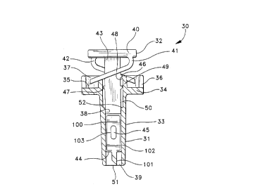
Fig. 3 shows a cross-s~ ' view of a lancet ass~ bly 30 that is similar to
the lancet as~lbly df-~';l~ in U.S. Patent 4,616,649 ~- f ~ above. However,
Flg. 3 shows a pl~,fc;..~,d blade 100 of the present il~ ion I ' in lan~t assemb;y
30 in place of the blade shown in U.S. Patent 4,616,649.
Lancet a~ , 30 shown in Fig. 3 includes a housing 31 and a slidably
mounted lancet blade holder ?S ' ~ 32. Housing 31 includes an Pl~n~ ti~ lower
por~on 33 and an upper flange pofion 34 having an ~ g ", g surface 35 and an
integ~al upwardly ~ " g annular wall 36 which together define a space 37 for
leceiving a pofion of lance~ blade holder assembly 32. A pair of arms 49 are located
2S within space 37 at the top of lower porlion 33, each arm 49 ~l ' g an integral
- 4 -
-, .. ~.. - . . . : . .
.. . . . .. . .... .. ... .
CA 0211~197 1999-01-18
abutment 48 extending into a passageway 39 in housing 31. Passageway 39 is defined
S by an internal surface 38 that extends from arms 49 in upper flange portion 34 to a
lower end opening 51 at the base of lower portion 33. In operation, lancet bladeholder assembly 32 is received by and travels within passageway 39. Passageway 39
also has an enlarged portion 50 in upper flange portion 34, which receives the top
portion of lancet blade holder assembly 32, described below.
Lancet blade holder assembly 32 includes an integral push-button top 4û with
resilient springs 41 and 42 and a shank 43 extending therefrom, shank 43 being
shaped to travel through passageway 39 in housing 31 during use. Pairs of integral
abutments 46 and 47 extend from opposite sides of shank 43 to cooperate with theinternally extending integral abutments 48 extending from each arm 49 to controlmovement of lancet blade holder assembly 32 within housing 31. A boss 45 is
located near a distal end 44 of shank 43 for receiving and holding blade 100 of the
present invention, with boss 45 being cold staked into an opening 103 in a base
portion 102 of blade 100.
Lancet assembly 30 is shown in Fig. 3 in a retracted position with a blade
portion 101 of blade 100 surrounded by lower portion 33 of housing 31 and contained
within lower end opening 51. In the retracted position, abutments 48 on arms 49 are
engaged with abutments 46 and 47 on shank 43 which effectively holds lancet blade
holder assembly 32 in a releasably fixed position within housing 31. In the position
shown in Fig. 3, abutments 46 are located on the proximal side of abutments 48
which prevents shank 43 from sliding in the distal direction and provides a tactile
indication to a user to indicate that lancet assembly 30 has not been used or activated.
However, after the lancet assembly 30 has been used, abutments 46 are located on and
abut the distal side of abutments 48, as shown in Fig. 4, with pressure being applied
by compressed resilient springs 41 and 42. In the position shown in Fig. 4, the user is
1 9 7
.
able to feel by the soft support under push-button top 40 that lancet assembly 30 has
been used.
To use lancet assembly 30, for example, the user holds housing 31 between a
thumb and third finger and holds lower end opening 51 of housing 31 in contact with
s the skin surface to be punct~lred on a patient's finger. The user then presses push-
I)utton top 40 with a second finger to force shank 43 through passdge~.dy 39 towards
lower end opening S l . As for~e is applied to push-button top 40, qbu~m~nt 46 is
forced over abi~ e.~t 4~ which causes lancet blade holder assembly 32 to thrust
forward and make ar, audible "snap", and project blade portion 101 beyond lower end
lO opening 51 to ~ u~l~;lul~ the patient's skin. The "snapn b:~' '~ to the user that the
lancet blade is fully f~,ct~n(~
Fig. 4 is a cross-sectionql view of lancet assembly 30 in an ~ ed position
during use a~ter bemg activated, wherein blade portion 101 of blade 100 projectsbeyond lower end openiDg 51 of housing 31 and is piercing the patient's skin. In the
5 extended position, resilient springs 41 and 42 are coln~Jl~d within space 37 in upper
flange portion 34 of housing 31 and hL - 48 on arms 4q are in contact with thebottom of push-button top 40, which stops distal end Illo~.,..le~l~ of shank 43. In this
position, blade portion 101 of blade 100 will have y~lllclul~d the patient's skin ;o begin
blood flowing from carillqn~-s in the patient's finger for testing y...yos~,s. After being
20 activated, the user release~s the pressure on pushbutton top 40 which allows colllplessed
resilient springs 41 and 42 to withdraw lancet blade 100 from the pUll~;lUl~; wound.
More particularly, as pressure is released from push-button top 40 resilient springs 41
and 42 retract blade holder ~ ~ 32 into lower end opening 51 of housing 31 so
that blade portion 101 is sul '~ d and contained within lower portion 33 of housing
25 31 for disposah
- 6 -
9 7
Fig. 5 is an enlarged side view of the prefelTed blade 100 shown in Figs. 3
and 4. As dcsc.il,ed above, blade 100 includes blade portion 101 and base po}tion 102,
with base portion 102 having an opening 103 for receiving boss 45 on shank 43 oflancet blade holder assembly 32. As shown in Fig. 5, blade po~tion 101 has a width A
of .60mm, a blade length B of 2.3mm, a shear length cf 0.874mm, and an included
angle O of 45~. Using equation (1), defined above, the shear pelce.-t~ c,c for blade 100
is 38%. The inventor has discovered th..l inc~ash~g the shear pe.-,e.lL~ of a lancet
blade, so that the blade performs more cutting action as it is piercing the patient's skin,
reduces the overall p~ ;o~ force needed to pierce the patient's s!~n ~us reducing
o the pain that the patient feels. In ~ lA;~ , the inventor has disoovered tha~ ucing
the width of the blade and the blade length, within reason so to avoid jeop~ldiLii1g the
qu..ntity of blood flowing from the ~ ..~ul~, also reduces p - force which
likewise reduces pain during ~ - Blade 100 of ~ present in~ention includes a ~ -
d~.~d blade width A of .60mm and an increased sbear pCl~ ~e ot 38 %, which
~5 c ' ~ provide a lancet blade that is much ~mproved over c;o~ lancet blades
since it causes the pat:ent much less pain during pf "- Of course, the above- ;listed l~ - - are merely ~ - P~ - y. other ~ C;~AC. could aiso be used. For
e , ', another e..ll~; e..l of bl2de 100 could ha~e a c s ~ l blade length of
1.5mm with a blade width A less than l.lmm, e.g., Imm, .60mm or .SOmm, or a
20 c~ ~. '~ -'bladewidthof l.lmmwi~han ~as~lshearpc..~ ~uptoto 100%.
Fig. 6 shows an alte~..ati~/e e...b~ of a lancet blade 110 for reduced
pain, which is b' ~ in lancet blade ? ~ S ~ 'y 30 shown in Figs. 3 and 4 in place
of blade 100. As shown, blade 110 has a base 112 wi~h an opening 113 that receives
boss 45 on sbank 43 to mount and hold blade 110. Blade 110 also includes an e, ~cn~
2S blade portion 111 that is offset from the center of the I ~ ' I axis of blade 110.
-7-
~.: , . : . ....
~ '
.~ ' , . -; - - . ' . .
1 9 ~ '
Offset blade portion 111 pelTnits the edge of blade 110 to be easily ground to have a -
cutting edge with a shear percentage of 100% In addition, blade 110 has a blade
width A of 1.0mm, a blade length B of 2.3mm, a shear length C of 2 3mm and an
included angle ~ of 25~. With a shear percentage of 100%, blade 110 con~innq-lly cuts
s the patient's skin during penel.,nion which causes even less pain than conventional
blades. The decreased width A of l.Omm on blade 110 also d~cltases the pain caused
during penetr~i( n of the patient's skin, as desc.;hcd above with respect to blade 100.
As for mqn~ ctnrin~ lancet q-scembli~s with blades 100 and 110, the blades
are made of surgical st~l ~nd ~re cold staked onto shank 43 of lancet assembly 30
10 using co..;~ ' ~ r ~l ...,. .r,,~ ~;.,,g techni~ues. Housing 31 and blade holder assembly
32 of assembly 30 are made of molded plastic. However, of course, these
t~;ne teC~ v~s and lc are merely exemplary, various other
r ~ h~g r.lethods and r/~riqlc could also be used.
In the fol~o ~ it is to be l~nrlpr~ood that the above~e~s~nhed
lS ~im~n-~ are simply illustrative of a lancet blade that provides a reduction in the
pain inflicted on a patient when piercing the patient's skin in accold~nce with the
present invention. Other suitable ~ ions and l--o lil~ .nS could be made to these
and still remain within the scope of the present i..~e.llion
- 8 -
... ... . ~ :
'- ~