Language selection

Search

Patent 2115347 Summary

Third-party information liability

Some of the information on this Web page has been provided by external sources. The Government of Canada is not responsible for the accuracy, reliability or currency of the information supplied by external sources. Users wishing to rely upon this information should consult directly with the source of the information. Content provided by external sources is not subject to official languages, privacy and accessibility requirements.

Claims and Abstract availability

Any discrepancies in the text and image of the Claims and Abstract are due to differing posting times. Text of the Claims and Abstract are posted:

  • At the time the application is open to public inspection;
  • At the time of issue of the patent (grant).
(12) Patent Application: (11) CA 2115347
(54) English Title: SCREW CAP FOR SEALING A BOTTLE OR THE LIKE
(54) French Title: BOUCHON A PAS DE VIS POUR BOUTEILLES OU AUTRES RECIPIENTS
Status: Deemed Abandoned and Beyond the Period of Reinstatement - Pending Response to Notice of Disregarded Communication
Bibliographic Data
Abstracts

English Abstract


A screw cap for sealing a bottleneck or the like with a substantially
cylindrical securing section (1) with a female thread (2) which can be
screwed on a male thread (7) of a bottleneck (8). The base of the screw cap
forms a sealing section (3). In addition, there is a stop to define the posi-
tion at which an edge of the bottleneck bears on the securing section. This
stop is on the inner wall of the cylindrical securing section and preferably
forms a bearing surface (6) in a plane perpendicular to the screw axis. As
the bearing surface is on the outside of the bottleneck, the face of the bot-
tleneck is free for the abutment of the sealing section or a seal. The stop se-
curely establishes a given screw-on distance even when the cap is detached
and refitted several times with differing torques and thus ensures that the
force with which the sealing section or seal bears on the face of the bottleneck is precisely defined. This also precisely defines the
pressure which, when exceeded, results in an increased internal pressure escaping from the bottle.


Claims

Note: Claims are shown in the official language in which they were submitted.

Claims:
1) A screw cap for the sealing of a bottle or the like;
o With an essentially cylindrical securing section (1) with
a female thread (2) which can be screwed onto a male
thread (7) of a bottleneck (8);
o With a sealing section (3) which essentially forms the
base of the screw cap; and:
o With a bearing surface (6), positioned on an internal
wall of the cylindrical securing section (1), for the
defined application of the securing section (1) to a
bearing edge of the bottleneck (8);
-- characterized in that, the bearing surface (6) proceeds in
a plane which is perpendicular to the screw axis.
2) A screw cap in accordance with claim 1, characterized in that,
the bearing surface (6) is ring-shaped.
3) A screw cap in accordance with claim 1, characterized in that,
the bearing surface (6) proceeds, in the area of a bearing
edge, or of the male thread (10) of the bottleneck, laterally
to the bottleneck (8).

4) A screw cap in accordance with claim 1, characterized in that,
the bearing surface is formed by the free edge of the cylind-
rical securing section.

Description

Note: Descriptions are shown in the official language in which they were submitted.


~115347
Reference: 722/18 Wo 1 04-26-1993
LEINE & RONIG
-- Patent Attorneys --
Sigurd Leine, grad. eng.
Dr. Norbert Konig, grad. phys.
Burckhardtstra~e 1
D-3000 Hannover 1
Telephone: (05 11) 62 30 05
Dr. Michael Hertrampf Our reference: 722/18 WO
Date: 04-26-1993
SCREW CAP FOR SEALING A BOTTLE OR THE LIRE.
/Stamp at bottom of each page/:
"Replacement Page"
The invention relates to a screw cap, of the type stated in the
introductory portion of claim 1, for the sealing of a bottle or the
like.
A screw cap of the type under discussion, in which the stop is, for
the defined bearing of the securing section, positioned on the edge
of the bottleneck in such a radial area that, upon being screwed
tight, it comes to bear on a frontal surface of the bottleneck, is
already known from DE 37 44 292 C2. Since the sealing section is
likewise applied to the edge of the bottleneck, which is, as a
rule, more internal, the reciprocal position of the securing sect-
ion and sealing part is precisely defined by that means. By that

- ~115347
Reference: 722/18 WO 2 04-26-1993
means, however, the magnitude of the force with which the sealing
section is pressed against the bottleneck or the sealing positioned
between the same is thereby defined. The result of this is that
the pressure by which the sealing or the sealing section raises
from the frontal edge of the bottle edge, which, as a whole, the
overpressure which is formed therefore opens, is also determined in
a precise manner.
A screw cap of the type under discussion, in which a braking ele-
ment with a run-up edge is provided on the internal wall of the
securing section, which lies in the area of the screw line of a
male thread and a bottleneck, and serves, upon the running up of
the male thread onto the braking element, to change the screwing-on
forces into a radial force component, and to thus overcome the
braking element and to thereby force the same in a direction radi-
ally outwardly, is already known from W0 90/10581. By that means,
the stoppage of the screw cap with a delay, in order to impede a
screwing of the cap up to the container aperture with too great a
torque, is thereby brought about. A precise aperture between the
base of the screw cap and the edge of the bottleneck can not
thereby be attained.

~1153~7
Reference: 722/18 WO 3 04-26-1993
The task which forms the basis of the invention is that of creating
a screw cap of the type under discussion for the sealing of a
bottle or the like, in which the constructive formation of the stop
is made easier, and a precise distance between the base of the
screw cap and the frontal edge of a bottleneck can be achieved.
The task which forms the basis of the invention is solved by means
of the concept which is stated by the characterizing portion of the
patent claim 1.
The basis of this concept is that of positioning the surface of the
stop on the screw cap in such a manner that it does not come to
bearing on the frontal edge of the bottleneck but, rather, upon a
bearing which is provided on the male thread of the bottleneck.
This is achieved through the fact that the bearing surface is
positioned on the internal wall of the cylindrical securing sect-
ion, in a plane perpendicular to the screw axis. In this manner,
a bearing is brought about, in the simplest case, directly at the
end of the screw thread which is turned to the frontal edge of the
bottleneck, forming a counter-stop on the external wall of the
bottleneck, and consequently determines the screwing-on depth of
the screw cap and thereby, at the same time, the distance of the
sealing section from the frontal edge of the bottleneck. Because
of this precisely-determined distance, it is possible to position
a flexible sealing between the sealing section and the frontal edge
of the bottleneck, the pressing together of which can, because of

~ l5347
Reference: 722/18 WO 4 04-26-1993
the precisely defined distance between the sealing section and the
frontal edge of the bottleneck, be determined in a precise manner.
This sealing is then in a position to form an overpressure valve.
If the pressure inside the bottle exceeds the bearing force of the
sealing which has been pressed together, then this presses together
somewhat further, so that a smaller aperture, through which the
overpressure can escape, is formed.
In accordance with the further development in accordance with claim
2, the counter-stop is formed by a ring-shaped, circular bearing
surface which is positioned on the external surface of the bottle-
neck.
It is possible, of course, in all cases to connect the sealing
section, as in DE 37 44 292 C2, by means of an elastic element,
with the securing section so that the prestressing of the elastic
element, and thereby the pressure at which the overpressure escapes
from the interior of the bottle, can be determined by means of the
stop in accordance with the invention.
The invention will now be illustrated in greater detail, in one
example of implementation, by means of the diagrams.

~1153~7
Reference: 722/18 WO 5 04-26-1993
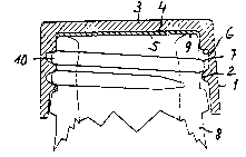
Figure 1: Depicts a section through one example of
implementation of a screw cap in accordance
with the invention; and:
Figure 2: Depicts the screw cap in accordance with
Figure 1, screwed onto the neck of a bottle,
which is partially represented.
The screw cap which is depicted in cross-section in Figure 1 con-
sists of a cylindrical securing section (1), on the internal wall
of which a female thread (2) is positioned. The base of the screw
cap forms a sealing section (3), on the internal wall (4) of which
a flexible sealing (5), such as of foam material of a certain com-
pressibility, for example, is brought to bear, and is held there,
preferably by means of adhesion, pressing in, or the like.
A ring-shaped bearing surface (6), which is directed in the direct-
ion of screwing on and acts as a stop during the screwing on, as is
made further evident in Figure 2, is formed on the end of the
female thread (2) which is turned to the base (4) of the sealing
section (3).
In Figure 2, the screw cap is screwed onto a male thread (7) of a
bottleneck (8), which is only partially depicted. It is to be
noted that the bearing surface (6) is applied to the last thread
part (10) which is placed the closest to a frontal edge (9) of the
bottleneck (8). By that means, the screwing-on depth of the screw

~1153~7
Reference: 722/18 W0 6 04-26-1993
cap is limited and precisely defined. At the same time, the aper-
ture between the frontal surface (9) of the bottleneck (8) and the
base (4) of the sealing section (3) is thereby defined. The seal-
ing (5), which consists of compressible material, is located within
this aperture. By means of a corresponding dimensioning of the
thickness of the sealing (5) and/or the dimensioning of the aper-
ture between the frontal surface (9) and the base (4), the force
with which the sealing (5) is compressed, and comes to bear on the
frontal surface (9), is precisely determined, even after being
repeatedly screwed on. This bearing force is, however, at the same
time, decisive for the pressure at which, upon being exceeded, an
overpressure escapes from the interior of the bottle.
.............

Representative Drawing
A single figure which represents the drawing illustrating the invention.
Administrative Status

2024-08-01:As part of the Next Generation Patents (NGP) transition, the Canadian Patents Database (CPD) now contains a more detailed Event History, which replicates the Event Log of our new back-office solution.

Please note that "Inactive:" events refers to events no longer in use in our new back-office solution.

For a clearer understanding of the status of the application/patent presented on this page, the site Disclaimer , as well as the definitions for Patent , Event History , Maintenance Fee  and Payment History  should be consulted.

Event History

Description Date
Application Not Reinstated by Deadline 2003-06-25
Time Limit for Reversal Expired 2003-06-25
Deemed Abandoned - Failure to Respond to Maintenance Fee Notice 2002-06-25
Inactive: Adhoc Request Documented 2001-08-01
Inactive: Status info is complete as of Log entry date 2001-07-24
Inactive: Application prosecuted on TS as of Log entry date 2001-07-09
Inactive: RFE acknowledged - Prior art enquiry 1999-05-07
Request for Examination Requirements Determined Compliant 1999-04-12
Inactive: Transfer reinstatement 1999-04-12
All Requirements for Examination Determined Compliant 1999-04-12
Request for Examination Received 1999-04-12
Application Published (Open to Public Inspection) 1993-02-18

Abandonment History

Abandonment Date Reason Reinstatement Date
2002-06-25

Maintenance Fee

The last payment was received on 2001-05-24

Note : If the full payment has not been received on or before the date indicated, a further fee may be required which may be one of the following

  • the reinstatement fee;
  • the late payment fee; or
  • additional fee to reverse deemed expiry.

Please refer to the CIPO Patent Fees web page to see all current fee amounts.

Fee History

Fee Type Anniversary Year Due Date Paid Date
MF (application, 6th anniv.) - small 06 1998-06-25 1998-06-11
Request for examination - small 1999-04-12
MF (application, 7th anniv.) - small 07 1999-06-25 1999-06-09
MF (application, 8th anniv.) - small 08 2000-06-26 2000-06-08
MF (application, 9th anniv.) - small 09 2001-06-25 2001-05-24
Owners on Record

Note: Records showing the ownership history in alphabetical order.

Current Owners on Record
MICHAEL HERTRAMPF
Past Owners on Record
None
Past Owners that do not appear in the "Owners on Record" listing will appear in other documentation within the application.
Documents

To view selected files, please enter reCAPTCHA code :


To view images, click a link in the Document Description column. To download the documents, select one or more checkboxes in the first column and then click the "Download Selected in PDF format (Zip Archive)" or the "Download Selected as Single PDF" button.

List of published and non-published patent-specific documents on the CPD .

If you have any difficulty accessing content, you can call the Client Service Centre at 1-866-997-1936 or send them an e-mail at CIPO Client Service Centre.


Document
Description 
Date
(yyyy-mm-dd) 
Number of pages   Size of Image (KB) 
Representative drawing 1998-05-26 1 5
Cover Page 1996-10-24 1 16
Abstract 1993-02-18 1 71
Description 1993-02-18 6 188
Claims 1993-02-18 2 32
Drawings 1993-02-18 1 12
Claims 2001-07-30 2 43
Description 2001-07-30 6 236
Reminder - Request for Examination 1999-03-01 1 117
Acknowledgement of Request for Examination 1999-05-07 1 174
Courtesy - Abandonment Letter (Maintenance Fee) 2002-07-23 1 183
PCT 1994-02-09 36 1,761
Fees 1996-05-16 1 41
Fees 1997-05-23 1 68
Fees 1995-04-03 1 37
Fees 1994-08-25 1 16
Fees 1994-06-01 1 36