Note: Descriptions are shown in the official language in which they were submitted.
W094/00866 PCT/VS93/05810
211~4~9
MANUAL OVERRIDE MECHANISM FOR
A REMOTE CONTROLLED CIRCUIT BREAKER
, . . . . . . . .
Cross Referellce ~o Related AppIication
This is a continuation in part of U.S. Patent application Serial No. 07/722,050, filed
June 28, 1991, entitled "Remote Control Circuit Breaker."
s Fie!d Qf The In~ention
The present invention relates generally to remote control circuit breakers and, more
particularly, to improvements in the control of remotely controlled circuit breakers.
Back~rQund O The In~ention
0 Remote control circuit breakers are commonly used for temporary interruption of
electrical service during peak use hours and for programmable lighting control of industrial
lDca~iorls. By opening and closing on demand from a remote location, ~hese circuit breakers
provide a sigI~ificant improvement over manually operated circuit breakers in terms of
conver~ience .
A variety of operatin~ mechanisms have beerl employed to realize remote control of
circuit breakers. One of the more common t~es of remote control mechamsms energizes a
solenoid to hold the circuit breaker in the open position. Such energization must be
` ~ continuous to prevent the circuit breaker from moving to the closed position.
Improved remote control mechanisrns have included the use of a motor to operate
the opening or closing of the contac~s. The motor is coupled to one of the contacts through
a gear, which rotates simultaneously with the shaft of the motor to cause the circui~ breaker
~ontæts to open and close.
A further improved remotely controlled circuit breaker mechanism is disclosed inthe above-referenced co-pending U.S. palent application Serial No. 07/722,050, which
2~ includes gear driving means responsive to "open" and "closed" control signals generated
from a remote location for moving a moveable one of a pair of electrical contacts through
associated ~ear means in order tO correspondingly interrupt or establish a circuit path.
SUBSTITUTE SHEEr
Wo 94/00866 Pcr/us93/05810
211~429
In ~11 such remote controlled circuit breaker mechanisms, it is desirable to provide
override means for manually controlling the circuit breaker when necessary by disabling or
overriding the remote control mechanism for the circuit breaker. There exists a distinct
need for a simple and conveniently operable manual override mechanism which is
5 particularly adapted for use with remote control circuit breaker mechanisms.
Summarv Of The Invention
It is a general object of the present invention to provide an improved remote control
circuit breaker arrangement which is convenient tO monitor and operate both locally and
o remotely.
It is a more specific object of the present invention to provide a remote control
circuit breaker having an improved manual override mechanism ~or disabling the remote
control mechanism when necessary.
It is a related object of this invention to provide an improved circuit breaker
5 ~ arrangement which includes a manual override mechanism of the above type which is
simple in design,~conveniently;manufactured, and capable of being easily assembled into
the~Qrcuit breaker.
In~accordance with the present inventiont the foregoing objectives are rea}ized by
; providing a rnanual override mechanism particularly adapted fQr use with a remotely
20 controllable circuit brealcer de~vice which includes: a ~lrst contact and a second contact
cooperatively arranged in the circuit path so as to provide current from the source to the
load and at least one of the contacts being movable for interrupting the power provided to
the load; gear driving means, responsive to "open" and "closed" control signals generated
from a remote location, for moving the movable contact so that the circuit path is
~5 correspondingly interrupted and established; and a rotatable gear lneans which responds to
the gear driving means and is coupled tO the movable contact so that the circuit path is
interrupted in response to the control signal.
... ,, . . ... . . ,.. . , . , . , , . . ; . . ,, ~ . . . ~ ~ ,
WO 94/00866 pcr/us93/os81~
2115429
Brief DeScrintion Of The Drawin~s
Other objects and advantages of the invention will be apparent from the following
detailed description and the accompanying drawings in which:
FIG. 1 is a perspective view of a remote controlled circuit breaker wherein the
manual override mechanism according to the present invention may be used, illustrating
the housing and cover;
FIG. 2 is a side view of the circuit breaker of Fig. 1 with the cover removed, showing
the circuit breaker in the~closed position;
FIG. 3a is a side view of the circuit breaker of FIG. 1 with the cover removed,
: showing the circuit breaker in the open position;
; FIG. 3b is a side new of the circuit breaker of FIG. 1 with the cover removed,showing the circuit breaker m~ the tripped position;
`
; FlG. 4 is a side view of the drcuit breaker with the cover removed, showing the
s ~ circuit~breakor with its remote control mechanism in the disabled position;
FIG. 5 is a perspective view illustrating the manual override mechanism used to
disabie the remote control mechanism~ for the circuit breaker of FIGS. 1-5, accord;ng to an
iDustrative embodiment~ of the ~present invention;
FIG. 6 JS a schematic d~agram of an electrical circuit which may be used to control
:~ ~ 20 the :clr~uit breaker arrangement of FIGS. 1-5 and to monitor and report the status of the
contacts; and
Fig. 7 is a perspective view of a preferred embodiment of the manually operated
override mecha~ism of this invention for use with the circuit breaker of FIGS. 1-S in order
to disable the remote control mechanism.
2s While the invention is susceptible to various modifications and alternative forms, a
specific embodiment thereof has been shown by way of example in the drawings and will be
described in detail. It should be understood, however, that it is not intended to limit the
.
WO 94/00866 Pcr/us93~os8lo
211S~29
invention to the particular form described, but, an the contrary, the invention is to cover all
modifications, equivalents7 and alternatives falling within the spirit and scope of the
invention as defined by the appended claims.
s Description Of The Preferr_Embodiment
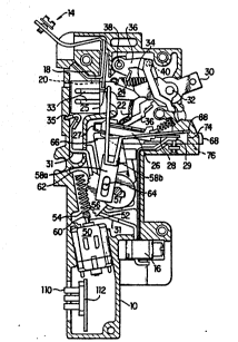
Turning now to the drawings and referring specifically to FIGS. 1-4, there is
illustrated a remotely controllable circuit breaker arrangement wherein the manual
override mechanism according to the present invention may be used advantageously. The
..
arrangement includes an insulative body or housing 10 closed at one face by a detachable
lO cover 12, a line te~rrninal 14 and a load terminal 16 for completing the circuit bet~Neen the
source and load (not shown). More specifically, the circuit path beginning at line terminal
..
14 carries current through stationary and movable contacts 18 and 20 and through a flexible
copper corlductor 22, which; IS soldered between a carrier 24 and a bimetal 28. The movable
~,
contact~20 may be formed~as~part of the carrier 24. A rigid conductive plate 29, which is
15 ~ ~ ~welded to~ the blmetai 28,~carries current from the bimetal 28 to the load terminal 16.
e above-described current path is controlled remotely and locally by a number ofdif~erent components, some of which are similar in structure and operation to the
corresponding componénts used~n Square D Company's circuit breaker Model No. QO-PI~ and ~descnbed in ~U.S.~ Patenl ~4,623,859, entitled REMOTE CONTROL CIRCUIT
: BREAhOER, issued on Nov. 18, 1986, and assigned to Square D Company, which is also the
assignee of all rigbts to the subject application. For example, the components associated
with an external operating handle 30 and a trip mechanism assemblyt whose descriptions
irnmediately follow, are similar in stmcture and operation to the corresponding
components in the above-referenced product and patent.
s Local control of the circuit breaker arrangement is provided using the external
operating harldle 30 pivotally mounted about an axis 32 in Ihe housing 10 to control the
contacl carrier 24. The upper end of the contact carrier 24 is rotatably secured to the
Wo 94/00866 Pcr/us~3/~sxl~
21~5~2!~
bottom of the operating handle 30 so that the contact carrier 24 can be rocked clockwise
and counterclockwise using a biasing spring 34. The biasing spring 34 is secured to the
bottom of the carrier 24 and to an equilibrium position on a trip lever 36 so as to urge the
carrier 24 toward the handle 30.
s In response to movement of the handle 30 to the right or left, the carrier 24 is
moved counterclockwise or clockwise, respectively, by the action of the~spring 34. The
handle 30 moves the top of the carrier 24 to either side of the equilibrium position, so that
the bottom of the carrier 24 biases the movable contact 20 to either the open or closed
, .
posltlon.
o l~e trip mechanism assembly:includes an armature 27, a bimetal member 28 and a
yoke 26. Upon the occurrence of a moderately sustained overload, from the contact-closed
position (FIG:. 2), the bimetal member~28 heats up and flexes to the right, causing the
armature 27 and :the :yoke~ 26 to swing counter-clockwlse (FIG. 3b) so as to release the
stand-off pressuN of the end of ;the~ trip lever 36, which is piwtable about a pin 38. This
5: ~; causes:the;trip 1ever 36~to swing clockwise and the spring 34 to pull the carrier 24 away
from: the stationa~y contàct ~l8 so: as~to interrupt the current path.
Similarly, upon the~occurrence of an extensive current overload, the yoke 26
manifests~a magne:tic force that attracts the armature 27, causing it to swing
: ; counter~loclnvise.~ This ~causes the trip lever:36 to swing clockwise and the spring 34 to pull
the carrier:24 so that the 0rrent path is interrupted.
After being tripped, the trip mechanism assembly is reset by cocking the operating
: handle 30 to the right so~that the~bottom of ~he operating handle 30 pushes pin 40. This
engagement of the pin 40 rotates the trip lever 36 in a counterclock~Ase direction to allow
the:end of the trip lever 36 to engage and set the armature 27.
2s In the circuit breaker arrangement described above, remote control is provided
~: using a m~tor 50 having a shaft ~2 which rotates in one direction tO pull the carrier 24 and
break the current path and which rotates in the opposite direction to allow the carrier 24 tO
: ~
WO 9q/00866 ~r/uSs3/0s8l0
211~429
be pulled by spring 34 to re-establish the current path. This is accomplished with a shaft
spri~g 54 which is mounted over the shaft 52, and a gear 56 which rotates about a pin 57 to
control a drive rod assembly or coupling arrangement 58 which includes (i) a substantially
rectangular plate member S~a hav~ng an aperture defined therein for accornmodating a
s coupling pin 64 linked to the gear 56, and (ii) a hook-shaped coupling member 58b having
a leg portion which extends into a hole 25 in the contact carrier 24 for pulling the carrier
24. The shaft spring 54 is secured at one end 60 to the shaft 52, using a torsional-type
pressure fitting, so that the shaft spring 54 rotates with the motor shaft 52. The gear 56
includes teeth 62 which interlock with ~he windings of the spring 54 to establish a linear
o relationship between the rotation of the shaft 52 and the rotation of the gear 56 about pin
57. For example, clockwise rotation of the shaft 52 may correspond to a counterclockwise
: ~rotation of the gear 56 about pin~57.
l~e coupling pin 64, which is secured to and protrudes out of the gear 56, responds
.
to the rotation of the gear 56 to control the position of the contact carrier 24 by virtue of
5 being coupled thereto through the drive rod assembly 58. As the gear teeth 62 move with
: , ~
the shaft spring 54, the side of the gear 56 opposite the teeth 62 rotates to the same degree,
thereby forcing the coupling pin 64 to rotate about pin 57. The movement of the coupling
pin 64 in the counterclockwise direction pulls the drive rod assembly 58 to the right in
`
order to:pull ~he contact carrier 24 away from the stationary contact 18. The drive rod
~: 20 : assembly 58 and particularly the dimensions of the plate member 58a and the leg por~ion of
the hook-shaped member 58b are such as to provide a gap on the right side of the coupling
pin~:64 when the gear 56 is fully rotated clockwise so that the contact carrier 24 does not
prevent the contacts 18 and 20 from closing.
In response to the motor operating in the opposite direction, the coupling pin 64
2s rotates in the clockwise direction and through the coupling arrangement provided by the
drive rod assembly 58 allows the biasing spring 34 tO return the contact carrier 24 to the
contacts-closed position.
wo 94/00866 rcr/uss3/o58lo
2115429
According to a feature of the present invention, the remote control circuit breaker
arrangement described above is provided with a manual override mechanism whereby an
operation may activate or use the breaker when the remote control mechanism is not in
use. More speciffcally, the pin 57, about which the gear 56 ro~ates, is defined as an integral
5 part of a ~lide mechanism 66 (FIG. 5) and may be used to override or disable the remote
control mechanics of the circuit breaker. As illustrated in FIGS. 2, 4-5, the override
mechanism of this invention incltldes a manually operated override button 68 which, when
presscd, laterally releases a holding force from the slide mechar~sm 66. The holding force
is implemented with a spring 72, supported by and surrounding an elongated member 70,
o urging a shoulder 74 of thc elongatcd member 70 against the inside surface of the housing
in a aperture 76. When thc compression on the spring 72 is released, an angled edge 78 in
the slide mechanism 66 forces the elongated member 70 toward the aperture 76 so that the
slide mechanism 66 no~longcr~ has a fLxed position from which the pin 64 can pull the
c y carner 24. Consequcntly, the slide mechanism 66, rather than the corltact carrier
s 24, movcs in rcsponse to~ thc rotation of ~ the shaft spring 54.
Thc slide mechànism 66 is also designed to prevent lockup of the gear 56 on the
shaft spring 54 when Ihc~remote control mechanics of the circuit breaker are not disabled
and arc beillg coMrollcd by thc motor 50. Becausc ihc shaft spring 54 can drive the gear 56
to eitber end of its teeth, it is~conceîvable that the motor S0 can o~erdrive the gear 56 to
20 ~ the ~extent that the shaf~t spring 54 is unable to rctain control over the position of the gear
56. As illustrated in FIG. 5, to prevent this potential lock-up situation, a torsion spring 86
may be sinlated in a slot 85 on the slide mechanism 66 and in a slot 87 in the gear 56 to
spnng-load the gear 56 in thc dock~ise or counterclockwise direction. The torsion spring
86 thereby prevents gear overdrive when the gear rotates in the- either direction, i.e., to
2~ allow the contacts to close or to force the contacts open.
In a preferred embodiment, the torsion spring 86 biases the gear 56 cloc}~ise when
the gear is overdriven during counlerclockwise rotation, so that the teeth 62 retain
.. , . , , ., ~ ,.. . ~.... . . , . . . , . .. "... . ,- . .. .. . . .
WO 94/00866 PCl~/US93/~)5810
2115429
engagement with the shaft spring 54. If the gear 56 is overdriven after its clockwise
rotation, the biasing spring 34 biases the gear 56 counterclockwise, by pulling the coupling
pin 64 via the contact c~rrier 24 and the coupling member 58, so that the teeth 62 retain
engagement wi~h the shaft spring 54.
S FIG. 7 shows a preferred embodiment of a manual override mechanism 150 which
uses an alternative design for the override button described above in connection with FIG.
5. The override button 152 shown in FIG. 7 operates similar to the override button 68 of
: FIG. S. In particular, the button 152 also cooperates with the slide mechanism 66 and
overrides or disables the remote control mechanism of the circuit breaker when the button
o is pressed laterally so as tO release a holding force form the slide mechanism 66.
~: ~ The releasable hoiding force is implemented by means of a spring 154 which is
~: mounted on an elongated pin-like extension 156 disposed on the button 152. As iliustrated
;~ in FIG. 7, the override button: 152 preferably has an elongated body integrally comprising a
reiativeb flat angled edge :portion 158 at its leading end. The edge portion 158 is linked to
:
5: a button-like extension 160 at its trailing end through a flat central portion 162 which
:; de~nes a~shoulder 164 about the junction thereof Wlth the button-like extension 160. The
elongated extension 156 proJects outwardly in a~ position substantially parallel to the
general length of the override button 152 from a support portion 166 extending from a side
of the nat central portion 162~ of the button 152.
~ ; With the above arrangement, the releasab1e force exerted by the spring 154 urges
, the shoulder 164 on the override button lS2 against a corresponding obstruction, such as a
ridge (wt shown) on the inside surface of the housing 10 about tbe apernlre 76 (see FIG.
2). In its ~ctive position,~the spring 154 is supported on one end by the elongated extension
156 and on the other end by the housing 10.
s In normal remote control operation the releasable holding force created by the
; spring 154 holds the leading angled edge 79 of the override button 152 against the angled
edge 78 in the slide mechanism 66. thereby causing the slide mechanism 66 to slide forward
wo 94/00866 2 1 1 ~ ~ 2 9 PCI'/1~93/05810
into a fixed position and allow2ng the coupling pin 64 associated with the gear 56 to pull the
contact carrier 24. When the override button 152 is depressed so that the shoulder 164 is
removed from engagement with the breaker housing, the compression on the spring 154 is
released. This, in turn, forces ~he override button 152 toward the aperture 76 and separates
5 the leading angled edge 158 from the slide mechanism angled edge 78. As a result, the slide
mechanism 66 no longer has a fixed position from which the coupling pin 64 can pull the
contact carrier 24. Consequently, the slide mechaI~ism 66, rather than the contact carrier
24, moves ih response to the rotation of the shaft spring 54, thereby disabling or overriding
the remote control mechamsm of the circuit breaker.
Referring once again to FIGS. 2 and 3, the circuit brealcer arrangement described
above also ~ncludes means for providing a reliable, and conveniently implemented, fail-safe
coMact status indicadon for local (versus remote) supervision. Because the hook-shaped
; leg portion of the drive rod assembly 58 Is shaped into an aperture 25 in the contact carner
24, mwement of the moveable contact 20 can be reliably detected by observing theis corresponding movement of the hook-shaped coupling member 58b. Thus, a portion 88 of
the~hook-shaped coupling member 58 is shaped tO be observed through an aperture (or
window)~90 in the cover 12 (FI~. 1) of the housing. Preferably, a- white cap (not shown) is
used on the end of the portlon 88 so that, when observed through the aperture 90, the white
cap indicates that the ~contacts 18 and 20 are together. Conversely, whe~ the white cap
20 cannot be observed, the contact carrier 24 has moved the white cap to its hidden position
on the motor side of the aperture 90. In either case, an observer can easily determine
whether the contacts 18 and 20 are closed by loo}cing at the front of the circuit breaker.
Because the hook-shaped coupling member 58 is secured to both the contact carrier 24 and
the gear 56 with no intervening, breakable parts, observing the portion 88 reliably indicates
2s the position of the contact carrier 24,
The circuit breaker arrangement shown in FIGS. 1-4 is also adapted to shunt
energy around the bimetal member 28 during short circuit conditions. Ex~ending down
WO 9~/00866 Pcr/uss3/os81o
~llS429
from the load lug 16 to arc plates 33 is a shunt terminal 31 (similar to the load terminal 29),
which dissipates arcing current during the short circuit conditions. An arc yoke 35 is used to
attract the arc and shunt current around the bimetal member 28. This type of arc shunting
practice is conventional in expanding the short circuit capacity of the breaker, which is
s otherwise limited by the current capacity of the bimetal member 28.
Most of the nonconductive components, e.g., the housing 10, the cover 12 and theoperating handle 30, may be made from a thermoset-type plastic. The hook-shaped
coupling member 58b and the springs may be manufactured using any durable metal.Electrically, the preferred circuit breaker arrangement is operated using signals
o which pass through a plug-in connector 110 and a circuit board assembly 112. The plug-in
connector 110 provides a conveniently removable interconnection between the circuit
breaker and a remotely located control/monitoring device, while the circuit board
assembly 112 carries the interface circuit for controlling the motor 50 and mor~itoring the
current delivered to the load through load terminal 16.
:: :
5 ~ FIG. 6 depicts a schematic~ diagram of the circuit on the circuit board assembly 112.
There are four leads carried by the plug-in connector 110; they include: a status lead 114,
- ~ positive and negative motor leads 116 and 118, and a neutral lead 120, which is common to
~ ~ the circuit breaker and the device providing the remote control signaling.
.
The motor 50, which is preferably implemented using a FK130S-10300 Mabuchi DC
motor, is directly connected to the circuit board assembly 112 at lead 118 and lead 122,
with lead 116 connected to the motor 50 indirectly through a parallel resistorfdiode
arrangement 124/125. I~e parallel resistor/diode arrangement 124/125 serves two
functions. The diode 125 may be used to provide current flow in a unilateral direction,
while the resistor 124 is used to control the power provided from lead 116 to the rnotor 50.
2s The ~value of the resistor 1~4 is selected according to the necessa~ current specified
tO operate the motor. In the event that the lead 116 is used to control a motor, e.g., for
controlling two or three circuit breaker poles. the resistance required will vary. For single
Wo 94/008~6 ~ 1 1 5 4 2 ~ P~r~US93/~)SXl~)
pole operation by the FK130S-10300 Mabuchi motor exemplified above, the value of the
resistor 124 is preferably 12 Ohms.
Forward and reverse rotation of the motor shaft 52 is then provided by applying the
appropriate voltage to either lead 116 or lead 118. Provision of +24 Volts over lead 116,
s witb respect to ground, will rotate the motor shaft 52 to cause the contact carrier 24 to
separate the conta~ts 18 and 20, and provision of -24 Volts over lead 118, with respect to
ground, will rotate the motor shafe 52 in the opposite direction to allow the contacts 18 and
20 to recoMect in the previously discussed marmer.
The current that is provided to the load is remotely monitored using a sensor which
is optically or magnetically coupled to the load side of the circuit breaker andcom~nuI~icatively coupled to the remote control/monitoring station via status lead 114 and
the plug-in connector 110. The status lead 114 may be directly connected (or coupled via a
radio or other nonwire iMerface) to the remote control signaling device to report whether
or not the current path to the load has been interrupted. This is accomplished using a line
5~ isolation circuit, e.g., opto-isolator 128 (FIG. 63, having an input connected to the load
terminal 16 (also shown~in FIG. 2 where lead 130 is connected to the shunt terminal 31)
and having an output, lead 114, connected directly to the remote control signaling device.
While current is being provided to the load, current passes through current limiting resistor
l36 to activa~e the opto-isolator 128. When activated, the opto-isolator 128 passes current
20 through its collector-emitter output ports so as to report to the remote control/monitoring
device ~na leads 116 and 114. When current to the load is intemlpted, voltage at lead 130 is
abseIlt and the output ports of the opto-isolator 128 do not pass current; thereby indicating
to the~re2~ote control/monitoring device that the contacts have interrupted the current
path provided to the load. The resistor 136, preferably 180k Ohrns at a 1/2 Watt rating,
2~ may be used at the input of the opto-isolator 128 to offset the heat dissipating through the
opto-isolator 128.
A diode 138 may be used to prevent reverse current from causing false contact
WO g4/00866 Pcr/l)s93/OSXl~)
2115~29
status readings in other parts of the system, e.g., from another circuit board assembly 112
OR-tied at lead 114. Such a configuration is described in detail in the aforementioned co-
pending application.
The signal which is transn~itted from the remote control/ monitoring device to open
s or close the contacts is preferably a DC pulse having a prescribed width. This pulse width is
selected in accordance with a calculated and premeasured test signal tQ rotate the gear 56
over a predetermined angle and, thus, move the contact carrier 24 linearly over a predeter-
mined length so that the contacts 18 and 20 are separated or closed.
TKe remote control/monitoring device may then check lead 114 to deterrnine if the
lo circuit breaker properly responded to ~he transmitted contacts-open (contacts-closed)
command. If the lead 114 indicates that the contacts-open (contacts-closed) command was
not obeyed~properly, ~the remote ~controltmonitoring device may then transrnit one or more
additiona~ pulses in an attempt ~to move the contact carrier 24 slightly further: Preferably,
the remote control/monitoring device transmits up to three additional pulses, one at a
5 ~ time, until the lead 114 indicates that the contact carrier 24 has rea~ed as instnucted.
Preferably, the original~ pulse width is about 47 milliseconds to open the contacts and about
14 nulliseconds to close the contacts. The pulse width of each of the follow-up pulses is
:~ ` : ::
equivalent to the original puise;width.
The foregoing description is not limited to the specific embodiment herein
20 descnbed, but rather by the scope of the claims which are appended hereto. For example,
:: : ~ :
although the invention has been described with reference to a single pole circuit breaker
tbe design may be easily adapted to a multipole circuit breaker to be operated from a
remote location. Moreover, in certain applications, it is conceivable that the motor/gear
assembly may be replaced by a solenoid operated mechanism. In particular~ the illustrative
2s manual override mechanism may be used effectively with alternative coupling
arrangemenls or drive rod assemblies different from that described above for coupling the
driving gear means to the movable contact.
:::
.. , . . . . , , ~, .. , v ., . ,, , ,,, " , . . . . . . . . . . . ..