Note: Descriptions are shown in the official language in which they were submitted.
~ YVO 93/05196 PCI`/US92/06622
7 2
PROCESS AND APPARATUS FOR TREATING
CELLULOSIC FIBER-CONTAINING FABRIC
TO IMPROVE DURABLE PRESS AND SHRINKAGE RESISTANCE
BACKGROUND OF THE INVENTION
1. Field o_the Inventlon
This invention relates to the treatment of cellulosic fiber-containing fabric
and artioles made from such fabric with a cross-linking agent in the presence of a
catalyst to improve durable press and shrinkage resistance properties of the fabric.
2. Discussion of Related Art
Treatment of cellulosic fibers (e.g., cotton, linen, hemp, rayon, etc.) ar,d
blends of fibers including cellulosic fibers with a cross-linking agent such as
formaldehyde in the presence of moisture and a catalytic acid producer such as
sulphur dioxide to improve the durable press (i.e., crease resistance) and shrinkage
properties of fabric and articles made of such fibers is well do^umented in published
literature and well known to those skilled in the art of fiber treatment. The physical
chemistry of the process is also well documented and the effect of the cross-linking
treatment on ce.lulosic containing fabric and articles of apparel made from such
fabric has been researched and published extensively.
WO 93/05196 PCI`/US92/06622 "~` `
2 1 1 .j ~i 7 2 ~ ~
Exemplary prior art processes are described in the patent literature, where
previous attempts have resulted in systems that are intended to solve some of the
more practical problems of applying cross-linking treatmen~ to finished article-~ of
apparel in a low cost, high volume (i.e., commercial scale) and efficiene manner, as
well as cross-linking treatment systems generally for cellulosic material.
The prsblems intended to be solved by the prior art processes and systems
are described in the various patents issued to inventors in this field, but thisdiscussion is concerned with prior art systems for treating cellulosic and cellulosic
blend fabrics that have been formed into finished articles of apparel on a high
volume, continuous production basis to improve the durable press and shrinkage
resistance properties of the apparel.
One approach tc treating cellulosic fabrics and articies made from such
fabric~ described in the patent literature involves treating garments in a closed
chamber using a gaseous cross-linking agent with steam and a gaseous catalyst,
such as is described in U.S. Patent Nos. 3,660,013 and 3,712,086 issued to G.
Payet and J. Forg on May 2, 1972 and January 23, 1973, respectively. This
process involved ~he generation of gaseous phase cross-linking agent by heating
powder of solid para-formaldehyde in a chamber containing the garmen~s to be
treated and then mixing the gas with steam and a gaseous cross-linking promotingcatalyst such as sulphur dioxide in the chamber so that the mixture permeates the
garments therein. The temperature in the chamber is then reduced for a period oftime and the temperature in the chamber is then increased to the cross-linking
temperature of the fabric and cross-linking agent. While successful, this process
has drawbacks in that heated trays used to vaporize formaldehyde required
~O 93/05196 2 1 1 5 S 7 2 Pcr/US92,06622
constant cleaning and maintenance, the moisture content of the fabric, while
critical, was difficult to control, and excess formaldehyde absorbed into the fabric
weakened the fabric and required careful cleaning of residual, non-cross-linked
formaldehyde from the garments after the cross-linking procedure to avoid
undesirable formaldehyde odors and irritant being left on the garments.
In U.S. Patent No. 3,837,799 issued to K. W. Wilson, R. Swidler and J. P.
Gamarra on September 24, 1974, a process is described for crease proofing
garments made from cellulosic fiber-containing fabric using gaseous formaldehydegenerated by heating para-formaldehyd~in mineral oil and subjecting cellulosic
fiher-containing fabric with previously applied latent catalyst to the gaseous
formaldehyde in a reaction chamber at about 90-150C. In this process, two
controlled procedures are required to expose the fabric to catalyst and
formaldehyde, the process is both temperature and moisture sensitive, and careful
cleaning of the formaldehyde and water soluble catalyst from the fabric is required.
U.S. Patent Nos. 3,960,482 and 3,960,483 issued to G.L. Payet on June
1, 1976 describe a durable press process involving a similar procedure for pre-
conditioning fabric with a water soluble catalyst and then subjecting it to
formaldehyde vapors and moisture before curing (cross-linking) the fabric and
formaldehyde at cross^linking temperatures. The problems of the prior art systems
are discussed in this patent, particularly the difficulties encountered in precisely
controlling moisture content in the fabric in the presence of a toxic gas and a
gaseous catalyst. In accordance with the process described in this patent, the
moisture content of the cellulosic fibers is controlled so they have over 20% weight
of moisture and contain a selected amount of catalyst when exposed to cross-
,
;:
WO 93/051g6 PCI/VS92/06622 ,.i. .
211~5~
linking formaldehyde vapor. This enables the process to be carried out at a lower
temperature (i.e., room temperaturei with a drastically reduced concentration offormaldehyde (6% by volume) as compared with prior art procedures. This
process, as with processes previously used, required separate moisture,
formaldehyde and catalyst applications to the fabric, and also was highly dependent
on the moisture content of the fabric for its successful implementation. The
moisture was introduced into the fabric as a spray, mist or fog, or was padded on
the fabric alone or with a catalyst. This left the problem of generating the gaseous
cross-linking agent and applying it to the fabric in a uniform manner as rapidly as
possible. Presumably, the cross-linking 40rmaldehyde vapor used in accordance
with the process described in the patent was generated from vaporizing solid form
para-formaldehyde, which entailed maintenance problems already discussed above~
,~ ~
U.S. Patent No. 3,865,545 issued to J.H. Forg and G. L. Payet describes an
~- other process for treating cellulosic fiber articles to impart a durable press thereto
involving vaporizing solid para-formaldehyde in a reaction chamber and exposing the
fsbric articles to the formaldehyde vapors, steam and gaseous catalyst for a period
,
,~.,
of time at a temperature initially ranging from 1 20F to about 14~F, followed by
cooling the fabric 10-30 by the time of completion of the procedure. Steam and
free chemicals are then purged from the chamber before the temperature in the
chamber is increased to cross-linking temperature. Steam and fresh air are then
circulated over the articles to clean them of residual odors. As in previously
described processes, control over moisture content, cross-linking agent
concentration and catal~/st content in the fabric as well as temperatures are all
critical to some degree; vaporization of solid para-formaldehyde is difficult to
", :
,: :
~:,
, ::
~o 93~0slg6 2 1 1 ~ ~ 7 2 Pcr/usg2/06622
control precisely; and the formaldehyde vapor generating system is maintenance
intensive.
A process f or the continuous treatment of continuous fabric and/or garments
for improved durable press characteristics is described in U.S. Pàtent No.
3,884,632 issued to G.L. Payet and B. D. Brummet on May 20, 1975. In this
patented system, the material to be treated was advanced through successive
treating stations where it was sequentially moisturized, subjected to formaldeh~/de
(generated by vaporizing solid para-formaldehyde) and catalyst, heated and cross-
I;nked, and cleaned in a continuous proc~ss.
U.S. Patent No. 4,032,294 issued June 28, 1g77 to R. D. Thompson, D.
Thompson and M. A. Beeley describes a similar process for continuously treating
garments using a ser;es of workstations and chambers to process equal sized
batches of garments.
' :
U.S. Patent No. 3,706,~26 issued on December 19, 1972 to R. Swidler and
K. Wilson describes a durable press process using formaldehyde and sulphur dioxide
to ~reat cellulosic fabrics. Moisture content of the fabric is described as being very
important to achieve a self-limiting reaction (cross-linking) but moisture, gaseous
formaldehyde snd gaseous catalyst are all conveyed to the fabric by different
routes and equipment, therefore requiring careful control over the system at alltimes to maintain proper proportioning of chemicals and moisture roaching the
fabric.
,
,
,~ :
WO93/05196 PCI`/US92/06622
5 7 2 6
U.S. Patent No. 4,067,688 issued on January 10, 1978 to G. L. Payet
descr;bes a durable press process for cellulosic fiber containing fabrics using
formaldehyde vapor and a liquid catalyst (aryl sulfonic liquid or acid) in a high
moisture environment. The moisture, formaldehyde and catalyst generally are
introduced to the fabric via different routes in the process, requiring careful control
over operating parameters.
A known commercial process involves direct injection of a known quantity
of liquid formaldehyde cross-linking agent into a stream of steam supplied at a
tsmperature sufficient to vaporize the foralaldehyde and then supplying a quantity
of the steam with entrained vaporized formaldehyde into a treating chamber
wherein a cellulosic containing fabric article has been placed for treatment. A
gaseous cross-linking promoting catalyst such as sulfur dioxide is then introduced
into the chamber and the fabric article is exposed to the mixture of steam,
formaldehyde, and sulfur dioxide for a preselected time. The free steam,
formaldehyde and sulfur dioxide (not retained by the fabric article) are then purged
from the treating chamber and the chamber's temperature is el~vated to cross-
linking temperature for a sufficient time to cross-link the cellulosic material in the
fabric, following which the chamber is cooled and the fabric is removed from thechamber. This process, while facilitating the delivery of formaldehyde to the fabric
article to be treated by using a stream of steam as a vehicle, still required close
! ' control over the suppiy of gaseous catalyst, along with all of the gaseous supply
tanks, conduits, valves and controls associated with the sulfur dioxide supply
system. Inside the treating chamber, the gaseous catalyst moved independently
of the steam and vaporized formaldehyde, so experimentation was required to
ensure that the appropriate amount of sulfur dioxide gas actually reached the fabric
WO93/05196 211~ 5 7 2 pcr/US92/06622
. ~ 7
with the cross-linking formaldehyde in a correct manner to ensure good cross-
linking results for the particular fabric undergoing treatment. Achieving minimum
strength loss in the treated fabric article and low residual free chemicals to be
removed from the fabric after completion of the cross-linking process required
careful control over the process.
Thus, while the known systems for cross-linking cellulosic containing fabric
articles using steam, cross-linking agent and cross-linking promoting catalyst in a
treating chamber have achieved some success, problems still remain in terms of
processing cost, speed and efficiency, ~s well as residual chemicals left in thecross-linked fabric. Fabric strength loss resulting from cross-linking and
achievement of shrinkage cor.trol with acceptable durable press quality remainedto be achieved at minimum cost.
BRIEF SUMMARY OF THE INVENTION
The present invention provides improvements in an apparatus and process
fortreating a cellulosic material containing fabric to improve its shrinkage resistance
and durable press properties, wherein steam is used as the vehicle for delivering a
cellulosic cross-linking agent to the fabric in a treating chamber in which the cross-
linking reaction takes place.
More specifically, this invention provides apparatus for treating a fabric
article containing cellulosic material including a treating chamber for receiving a
fabric article to Ibe treated, a source of pressurized treating steam and a conduit for
carrying the treating steam from the source of treating steam into the treating
chamber; an ejector type pump having a suction zone associated with the conduit
WO 93~05196 P~/US92/06622
211~572 8
and arranged to receive treating steam from the conduit for generating suction at
the suction zone and to discharge the treating steam into the treating chamber;
means for supplying at least a liquid cellulosic cross-linking agent to the suction
zone of the pump for entrainment with the treating steam; the treating steam
having a temperature sufficiently high to vaporize the cellulosic cross-linking agent
upon entrainment of the latter into the treating steam; and a means for supplying
a cross-linking promoting catalyst into the treating chamber. This system enables
the cellulosic cross-linking agent to be entrained and vaporized in the treating steam
at the suction zone of the pump and to be discharged wi.n the treating steam into
the treating chamber for treating a fabric erticle in the treating chamber.
The invention also provides a means for supplying a cross-linking promoting
catalyst into the treating chamber by supplying the catalyst in liquid form to the
suction zone of the pump for entrainment with the treating steam, and a means for
controlling the level of the cross-linking agent at the inlet area of the suction zone
of the pump.
The invention furthermore contemplates a me~hod f or treating a fabric article
as described above including the steps of providing a steam driven ejector type
pump in a treating steam conduit and introducing the cross-linking agent into the
treating steam by entraining it in liquid form into the steam at the suction zone of
the pump, where the cross-linking agent is vaporized and carried into the treating
chamber with the treating steam.
The invention furthermore contemplates the step of introducing a cross-
linking promoting catalyst into the treating chamber by entraining a normally liquid
~ .~WO 93/05196 2 1 1 ~ S 7 2 Pcr/US92/06622
g
catalyst into the trsating steam at the suction zone of the steam driven ejector type
pump, vaporizing the catalyst in the steam and then delivering both the steam and
the catalyst to the treating chamber.
Also, in accordance with the invention, both the cross-linking agent and the
catalyst may be simultaneously introduced into the tr~ating steam and vaporized
therein at the steam driven ejector type pump by supplying a rnixture of the liquid
cross-linking agent and liquid catalyst to the suction zone of the ejector type pump
while it is driven by the treating steam.
The invention also contemplates a process for treating a fabriG article as
described previously wherein the fabric article is exposed to gaseous ammonia,
; preferably with steam, in the treating chamber before the cellulosic material is
, cross-linked.
,;
;~ This invention also contemplates a process for treating a fabric article as
, ~ ~
; ~ ~ described previously wherein the cellulosic cross-linking agent and the cross-linking
promoting catalyst are introduced into the treating chamber by directly injecting the
cross-linking agent and catalyst into the treating steam that is supplied to thechamber, following which the normal cross-linking process is carried out. In
accordance with this process, the cross-linking agent and catalyst may be supplied
to the steam independently or simultaneously by mixing them together before
injection into the steam, and the steam is supplied at a temperature above the
vaporization temperature of the cross-linking agent and catalyst.
-, :
i ,
~ ~ .
WO 93/05196 PCI'/US92/06622 ~
2 1 1 5 5 7 2 1 0
The invention furthermore contemplates utilizing specific liquid cross-linking
agents and cross-linking promoting catalysts as described herein.
DESCRIPTION OF THE DRAWINGS
The present invention, including its characteristics and features, as well as
preferred embodiments thereof, will be described in more detail in connection with
the appended drawings wherein:
Figure 1 is a schematic illustration of one embodiment of apparatus utilized
for carrying out the invention including a steam driven ejector type pump;
Figure 2 is a similar schematic ill~stration of the invention wherein liquid
cross-linking and catalyst chemicals are directly injected into a stream of treating
stearn; ~
Figure 3 shows a detail of an ejector type pump utilized in Figure 1;
Figure 4, shows a detail of an alternative ejector type pump useful in the
Figure 1 embodiment; and
Figure 5 schematically illustrates a flowchart depicting the processes
embodying the invention.
DETAILED DESCRIPTION OF THE PREFERRED FMBODIMENTS
OF THE INVENTION
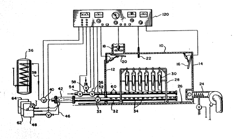
With reference to Figure 1, apparatus embodying this invention for treating
one or more fabric articles containing cellulosic material to improve the shrinkresistance properties of the fabric articles during laundering and to improve the
durable press properties of the fabric articles includes a reaction or treating
chamber 10 having a door 12 for loading fabric articles into the chamber, a fresh
air inlet 14 having a controllable closure 16 and an exhaust vent 18 having a
~WO 93/05196 2 1 1 ~ ~ 7 2 Pcr/US92/06622
1 1 ~
controllable closure 20. A temperature probe 22 and a heater 24 are also
connected to the chamber. Rails 26 are provided on the floor of the chamber for
supportin~ and ~uiding a cart 28 arranged to carry finished fabric articles 30 into
and out of the chamber 1Q through door 12.
A first conduit 32 is provided near the bottom of the treating chamber 10
and includes openings 34 for providing communication between the interior of theconduit 32 and the interior of the chamber 10. A control valve 33 is provided tocontrol flow through conduit 32. Conduit 32 is connected to a source 36 of
treating steam under pressure via a stea~n conduit 38 and a control valve 40 as
seen at the left of Figure 1. A steam driven ejector type pump 42 is provided
between the steam conduit 38 and the conduit 32 for entraining a liquid chemicalinto a stream of treating steam supplied to the pump 42 and discharged into the
conduit 32.
A preferred embodiment of an ejector type pump useful in carrying out the
process in accordance with this inven~ion is shown in more detail in Figure 3, and
includes an inlet end 39 connected to steam conduit 38 and an outlet end. 39a
connected to the conduit 32. The pump includes a low pressure suction zone 44
created by the accelerated flow of pressurized steam through the suction zone inaccordance with well-known principles. The pump includes an inlet 39b for fluid
to be pumped by the action of the driving steam, with the inlet 39b connected toa supply conduit 46 for fluid supplied to the suction zone M of the pump. In
accordance with well-known principles of operation involving ejector type pumps,the supply of pressurized steam to the inlet end 39 of pump 42 produces a suction
at the suction zone 44 which will pump fluid (in this case liquid) through the supply
WO 93/05196 PCI`/U$92/06622 f~
211!~572 12
conduit 46 by entraining and mixing the driving steam and pumped fluid together.The mixture is dischar~ed through the outlet end 39a of the pump and flows
through conduit 32 eventually into the treating chamber 10.
In Figure 4, an alternate embodiment of an ejector type pump 42' is
illustrated and includes a venturi suction zone 44' connected to a supply tube 46
for liquid to be pumped with the steam. The embodiment of ejector type pump
illustrated in Figure 4 operates in the same manner as the pump illus~rated in Figure
3; specifically, pressurized stearn supplied through conduit 38 is accelerated as it
passes through the suction zone 44' o~the pump creating a low pressure for
pumping fluid through supply tube 46.
In accordance with this invention, steam supplied through conduit 38 is
maintained at a temperature at or above the vsporization temperature of liquid
supplied through supply tube 46 so that the mixture discharged from the steam
driven pump is in vapor form. It is to be understood that the term "ejector typepump" is intended to broadly encompass any fluid driven pump arrangement
wherein suction is created by a change in the velocity or pressure of pumping ordriving fluid at a suction zone and wherein a fluid to be pumped is supplied to the
suction zone. In all instances it is intended that the driving and pumped fluids will
be mixed in a pump of this type.
The liquid ahemical supply tube 46 is connected at its outlet end to the
suction zone 44 of the pump 42 and at its other end is connected to a supply 48
; ~ of liquid chemical to be entrained in the treating steam. A valve 50 is provided to
control the flow of liquid chemical into the supply tube 46. The supply source 48
' : ~
~NO 93/05196 21 1 a a 7 2 Pcr/U592/06622
in its simplest embodiment may comprise a tank having an inlet valve that is
controlled by 8 float that senses liquid level of chemical in the tank and maintains
the chemical in the tank at a predetermined selected level that will maintain a liquid
level in the supply tube 46. The iiquid level in the supply tube 46, of course,
determines the rate at which liquid chemical will be taken up at the suction zone
44 of the pump 42 in accordance with well-known principles. It is to be
understood that any suitable arrangement could be- provided to- secure the
maintenance of a predetermined liquid level of chemical in the supply tube 46 tocontrol the rate at which the liquid chemical will be entrained in the moving stream
of steam driving pump 42. ~ -
Operation of the system described thus far is as follows. The door to
treating chamber 10 is opened and a cart 28 with fabric articles such as finished
garments made of fabric containing a cellulosic material is wheeled into the
chamber on the rails 26. The door 12 is closed and the closures 16 and 20 are
closed~ Pressurized steam from source 36 is then driven through the pump 42 and
into chamber 10 via conduit 32. The initial steam supplied to the chamber 10 mayor may not contain any liquid chemical supplied through tube 46 at the pump 42,
depending upon whether it is desired to introduce the liquid chemical into the
chamber 10 at this point or merely to provide moisture to the fabric articles 30.
At the desired time, valve 50 is opened and liquid chemical is supplied to the tube
46 and entrained in the driving stream of steam passing through pump 42 into theconduit 32 and ultimately into the chamber 10. The temperature of the steam
moving through the pump 42 is maintained at a suitable level to ensure that the
liquid chemical introduced through the tube 46 will vaporize as it is entrained in the
steam and before it enters the treating chamber 10. The fabric articles 30 thus will
WO 93/05196 PC~/US92/06622 ,~ ~.
211~72 14 `
be exposed to a uniform mixture of steam and liQuid treating chemical within thetreatin~ chamber 10 as the steam and chemical condense on the fabric of the
ar~icles 30.
In accordance with this invention, it is desired to introduce liquid cellulosic
cross-linking agent as a liquid chemical. introduced to the supply tube 46 at
connected to pump 42. In this manner, a liquid cross-linking agent can be supplied
with the trealting steam supplied to the chamber 10 in a manner that is self-
regulating, as deterrnined by the level of liquid cross-linking agent maintained in
supply tube 46 and the suction capacit~c of the ejector type pump 42. More
specifically, the use of the ejector type pump 42 enables the use of a minimum
amount of cross-linking agent required to carry out the cross-linking of the cellulosic
material in the fabric articles 30. The only major controls required are the pressure
and temperature of the treating steam, the level at which the steam can generatesuction at the pump suction zone, the liquid level of cross-linking agent in thesupply tube 46, and the time of injection of the steam to ensure that the fabricarticies 30 are exposed to a desired quantity of steam and cross-linking agent.
Various arrangements can be used to introduce a cross-linking promoting
catalyst into the treating chamber 10. In accordance with one preferred
embodiment of such apparatus, a gaseous catalyst may be supplied to a second
coriduit 52 under the control of appropriate valves 54, 56 and/or 58. Second
conduit 52 includes openings 60 to provide communication between the interior ofsecond conduit 52 and the interior of treating chamber 10. Thus, at an appropriate
point during the treating process, one or more valves 54, 56 or 58 are suitably
controlled so as to provide communication between second conduit 52 and a
.--WO 93/05196 2 ~ 7 ~ PCr~US92/06622
source of cellulosic cross-linking promoting catalyst in gaseous form so that the
gaseous catalyst is introduced into the interior of chamber 10 with the steam and
c011ulosic cross-linking agent that has been supplied through conduit 32.
In accordance with known methodology, the fabric articles 30 are exposed
to a known concentration of steam, cross-linking agent and catalyst f or a
predetermined time interval, following which the chamber is purged by opening the
closures 16, 20 and the chamber is ventilated by operating an exhaust fan in theexhaust vent 18. Following the ventilation of the chamber 10, the closures 16 and
20 are closed and the temperature in tl~le chamber is elevated by activating theheater 24 until the chamber reaches a desired cross-linking temperature depending
upon the fabric articles 30 and the cross-linking agent and catalyst used in theprocess. Following cross-linking, the temperature in the chamber is lowered and
the finished articles 30 are removed frorri the chamber through the door 12.
Beneficial results can be obtained by utilizing the ejector type pump 42 to
entrain a normally liquid cross-linking promoting catalyst into the driving steam
supplied through conduit 32 to the chambsr 1 C). In this embodiment, a rnixture of
liquid cross-linking agent and liquid catalyst appropriate for the cross-linking agent
is provided in the supply source tank 48 and is supplied to the pump 42 through
supply tube 46, in the same manner as the cross-linking agent alone was suppliedin the embodiment described above. Thus, both cross-linking agent and catalyst
in liquid form can be drawn into and vaporized in the stream of steam moving
through pump 42 at its suction zone 44 and then supplied as a mixture of steam,
cross-lihking agent and catalyst to the interior of the chamber 10 for use in the
above-described cross-linking process.
.
WO 93/OSlg6 PCr/US92/06622 ,~
211S572
~
In still another embodiment, the liquid catalyst can be supplied through tube
46 from a separats supply tank 62 or a separate steam driven ejector type pump
(not illustrated) could be provided for entraining liquid catalyst into a stream of
steam carried by conduit 32 or by a separate conduit ~not illustrated) having
openings for providing communication between the separate conduit and the
interior of the chamber 10.
In any of the errlbodiments thus far discussed, still another liquid chemical
supply tank 64 can be provided to supply liquid chernical to the stream of steamcarried by conduit 32 through pump 42 er another ejector type pump driven by a
stream of pressurized steam that is then supplied to the interior of the treating
chamber 10. The ejector type purnp thus provides a simple expedient for entraining
; ` liquid chemical into a stream of steam supplied to the interior of treating chamber
10. Since the steam temperature will be maintained above the vaporization
temperature of the liquid chemical, the liquid chemical will be vaporized in thetreating steam, so that virtually no controls are requirad within the chamber 10 to
ensure that the fabric articles 30 are uniformly exposed to a mixture of steam and
the chemical entrained in the steam.
In accordance with another embodiment of the invention, gaseous ammonia
can be supplied to the interior of treating chamber 10 to further condition the fabric
articles 30 during the treating process. The gaseous ammonia may be supplied
through conduit 52 or may be supplied through the conduit 32 with treating steam.
The process utilizing ammonia will be described in more detail below.
~ ~ .
.
-~VO93/05196 211 ~ ~ 7 2 rcr/US92/06622
17
With reference to Figure 2, apparatus for introducing steam and liquid
chemical includes a direct injector 70 arranged to inject liquid chemical under
pressure from a supply tank 72. An appropriate pump 74 and control valve 76
provide a pressurized supply of liquid chemical to the injector 70 for direct injection
of the liquid chemical into a flowing stream of steam supplied through conduit 78
connected to a source of steam 80. An appropriate valve 82 controls the flow of
steam through conduit 78, which in turn is connected to-a supply conduit 84 thatcorresponds to supply conduit 32 in the embodiment of Figure 1. Thus, the conduit
84 includes openings 86 that provide communication between the conduit 84 and
ths interior of treating chamber 10, which otherwise corresponds with the treating
chamber 10 illustrated in Figure 1.
Preferably, the direct injector 70 is arranged to cause direct head-to-head
, impingement of a stream of steam flowing into conduit 84 and liquid chemical
supplied to the injector 70.
In accordance with this embodiment, a stream of treating steam under
pressure is supplied from source 80 through conduit 78 and conduit 84 under the
control of valves 82 and 90. At an appropriate time, liquid chemical from tank 72
and delivered by pump 74 is supplied to the injector 70 for direct injection into the
moving stream of steam supplied through conduit 78. The liquid chemical is
entrained in the moving stream of steam supplied to the conduit 84 and ultimately
is discharged into the interior of treating chamber 10 to provide an atmosphere in
the chamber suitable for carrying out the fabric treating process outlined above.
The temperature of the steam supplied through conduit 78 is maintained at a
suitable level to ensure vaporization of the liquid chemical supplied through the
:
:.
WO 93/0~196 PCI`/US92/06622
2 l1 ~ 57 2 18 `
injector 70 so that the chemical is uniformly distributed throughout the interior of
the chamber 1 t) with the steam supplied through conduit 84.
In accordance with this embodiment, a liquid cellulosic cross-linking agent
is supplied through the injector 70 for entrainment in the stream of treating steam
supplied through conduit 84. In addition, a liquid cross-linking promoting catalyst
can be supplied by mixing the catalyst with the cross-linking agent in the tank 72
and supplying the mixture to the injector 70. In accordance with this arrangement,
the steam, cross-linking agent and catalyst will be supplied as a mixture to treating
chamber 10 via conduit 84. Alternatively, the liquid catalyst may be supplied
through a separate tank 92 connect~d to the injector 70 through an appropriate
conduit means incorporating suitable valving and purnping means. If desired, still
other tanks ~not illustrated) could be connected to the injector 70 in conjunction
with suitable pumps and valving arrangements so that additional liquid chemicalscan be injected directly into the stream of treating steam supplied through conduit
78 and introduced to the chamber 10 through conduit 84.
A second conduit 92 including openings 94 is provided to supply other
chemical treating agents to the interior of treating chamber 10 under the control of
vaive 96. The second conduit 92 normally will supply a gaseous treating agent,
such as a liquid cross-linking promoting catalyst, ammonia, or other desired agents
to the interior of treating chamber 10 as part of the fabric treating.
In Figure 5 there is illustrated a flowchart for carrying out cross-linking of
cellulosic material containing fabric articles 30 in chamber 10 in accordance with
this invention. As illustrated, chamber 10 is in communication with a source of
~-~O93/OS196 2~ 72 PCI/USg2/06622
19
heat 100, and includes an exhaust vent 102 and a fresh air vent 104. Fabric
srticles containing cellulosic material such as garments 30 are periodically placed
in the treating chamber 10 where an atmosphere of steam, vaporized cellulosic
cross-linking agent, and vaporized or gaseous catalyst is provided. The vaporized
cellulosic cross-linking agent will be supplied as a liquid that has been vaporized and
entrained in a quantity of treating steam supplied through conduit 106 by direct
injection or by entrainment at^the suction zone of an~jector-type-pump prov~ded
at point 108 along the conduit 106. The vaporized or gaseous cross-linking
catalyst will be supplied as a liquid directly injected into the treating steam in
conduit 106 at point 108, a liquid entrai~ed at the suction zone of an ejector type
pump provided at point 108, or as a gas supplied via conduit 1 12. If desired, the
ammonia in gaseous form rnay be supplied either directly to the interior of treating
chamber 10 via conduit 1 14 or may be injected into the treating steam via conduit
116 before the cross-linking is carried out, preferably before the fabric articles are
1 S exposed to the cross-linking agent and catalyst.
After the fabric articles 30 are exposed to the cellulosic cross-linking agent,
catalyst and steam in the chamber 10, cross-linking is carried out at a cross-linking
temperature in accordance with the procedure described previously. Finished fabric
articles 30 are then removed from the treating chamber for further processing and
distribution~
A central control panel 120 preferably incorporating a microprocessor is
connected by appropriate leads to the various actuators, pumps, valves,
temperature probe, heater and blower utilized in the system illustrated in Figure 1.
The central control panel enables an operator to observe operation of the entire
WO 93/05196 PCI`/US92/06622 ~r
2 1 1 ~i 5 7 2 2 0 ' ; j
system. For example, opening and closing of the closures 16 and 20 as well as
operation of the vent fan and the exhaust vent 18 can be operated at the proper
time under the control of a microprocessor associated with the control panel 120and the operation of the heater 24, including its associated gas supply valve and
blower likewise can be controlled for proper operation to control the temperature
within the chamber 10. A temperature sensor probe 22 enables sensing of the
temperature within the chamber 10 and various other sensors ~not illustrated) can
be utilized as well to monitor the interior of the reaction chamber 10. The timeinterval for delivery of treating steam through conduit 24 can be controlled through
the control panel 120 by controlling the epening and closing of valves associated
with the steam supply conduit 32 and the ejector type 42. The flow and the timing
of flow of gaseous ch~micals through conduit 52 likewise can be controlled via the
control panel 120 by controlling the opening and closing of associated valves 54,
56 and 58. Preferably, the various control valves are electrically actuated, as are
the various pump motors and blower motors utilized in the system. It will be
understood that any suitable control panel arrangement could be utilized in
accord~nce with well known and accepted procedures and standards in the industryand in a manner that will be apparent to persons skilled in the art of chemical
processing. Lilcewise, the microprocessor contemplated for use in connection with
the control panel 120 can be a typical personal computer type microprocessor
containing program instructions convertible into electrical signals for controllin~ the
various equipment associated with the apparatus illustra~ed in Figure 1.
Examples of the results obtained are described below.
~ WO93/OS196 211 a ~ 7 2 PCr/US92/06622
21
EXAMPLE 1
Samples of U.S. Testing Cotton Twill, U.S. Testing 80 Square Cotton and
Cotton Je~sey measuring approximately 18 in. x 24 in. were subjected to a singlehousehold laundering cycle (warm wash, cool rinse) and a permanent press drying
cycle. The samples were tested for shrinkage (i.e., the washed sample dimensionswere compared with the dimensions before washing) and then washed four more
times. After the fifth wash cycle, shrinkage was measured again.- Shrinkage-was
measured lengthwise (L) and widthwise (W) of the fabric samples and shrinkage
was determined as a percentile of the original fabric dimensions.
In addition, the durable press properties of the twill and 80 Square samples
were measured by the American Association of Textile Colorists and Chemists TestProcedure No. AATCC Test Method 124-1984: "Appearance of Durable Press
Fabrics After Repeated Home Laundering." Essentially, the samples were launderedas described above and dried using standard home laundry equipment with a
durable press (permanent press) cycle. The samples were then permitted to relax
for a predetermined period of time and their surface appearances were compared
with a chart, yielding a durable press rating (DP) of 1 to 5, with 5 being the highest
rating. The results were as follows:
TABLE 1
A. Single Wash Cycle
Shrinkage (%)
Fabric L W DP
Twill 9
80 Square 5 4
- 25 Jersey 7.5 7.5
, ':
WO 93/05196 PCI/US92/06622
211~572 22 ```
B. Five Wash Cycles:
Shrinkage (%)
Fabric L W DP
Twill 11 0
80 Square 7.5 7.5
Jersey 11 6
Similar samples of the same fabric described above were then placed in a
stainless steel reaction chamber as described in Figure 1 herein, the chamber
measuring approximately 6 feet wide by 10 feet long by 7 feet high. Access to the
chamber was through an entry door in one end of the chamber and two steam
conduits with openings along their lengths extended along the lower sides of thechamber sidewalls. An additional conduit with discharge ports extended the length
of the chamber for supplying a gaseous chemical to the interior of the chamber.
A direct injector as described above with reference to Figure 2 for injecting liquid
chemical directly into a stream of steam was provided so that steam and entrained
vaporized chemical could be suppiied into the chamber 1û via the steam supply
conduit. The reaction chamber also included various accessories for enabling
carrying out a cellulosic cross-linking process, including fresh air inlet and outlet
vents with controllable closures, an air blowing fan for ventilation of the chamber,
an open combustion gas heater and a hot air oirculation system for heating the
chamber interior. Also provided were a supply tank for liquid cellulosic cross-linking
agent, a pump and conduit system for supplying cross-linking agent to the injector,
a steam supply source at 17 psi connected to the injector and the steam conduit
in the reaction chamber, and a conduit for gaseous chemical to be supplied into the
reaction chamber. The central control panel was wired to the pump, fan, air inlet
and outlet closures, as well as various solenoid operated flow control valves
~ vog3/oslg6 211~572 PCI/lJSg2/06622
provided in the liquid cross-linking agent, steam and gaseous chemical supply
conc i ts. A microprocessor incorporated in the control panel was pro~rammed to
control timing of various portions of the treatment cycles to be carried out in the
chamber, as well as the timing of flow of steam and chemicals. The liquid cross-linking agent supply tank was calibrated to provide a measuring system for
indicating quantity of chemical solutions supplied to the injector. Specifically, a
translucent tank was provided with v~lume graduations in English unit increments(i.e., feet-inches) and, through calibration tests, it was determined that the tank
held .36 gallons of chemical per inch of vertical height of the tank (approximately
1.36 liters/inch or .54 liters/cm.) Wit~ the chamber sealed, and using liquid
formaldehyde as the cellulosic cross-linking agent, steam at 17 psi and at
approxlmately 220 F was supplied to the chamber through the injector and steam
conduit for 1.5 minutes, while 2400 grams of liquid formaldehyde were injected
and entrained in the steam at the injector. 15 Ibs. of sulfur dioxide gas wa~ then
injected into the chamber through the gaseous chemical supply conduit. After a
soak period of 2 minutes, the free cross-linking agent and catalyst not retained on
the fabric samples, along with free steam and moisture, were vented from the
chamber and the chamber was sealed again. The temperature in ~he chamber was
raised to 260F to cross-link the samples are then steam at 60 psi was injected
into the chamber for five minutes to clean residual formaldehyde from the samples.
The chamber was then vented and cooled and the samples were removed.
Following removal of the samples, they were washed in the same manner
as the control samples and tested for shrinkage, strength loss, durable press
properties and residual unreacted formaldehyde (expressed as parts per million or
ppm) remaining in the samples. Strength Loss lengthwise (L) and widthwise (W)
WO 93/0~1~6 PCr/US92/06622 ~ ~.
Z1~72
24
was measured by using a standard ball burst tester (Mullen tester) except for the
jersoy knit, where strength loss was determined in a single ball type burst test. The
results were as follows:
TABLE 2
PPM
Shrinkage (%)* Strength Loss ~/0) DP Residual
Fabric L W L W
Twill 4 0 39 41 3 374
80 Square 1 1 57 53 3 517
Jersey 2.5 2.5 39 538
* Shrinkage Measured after single wash cycle
This test indicated that the process used met or exceeded commercial
specifications for shrinkage control and durable press for the samples.
Similar samples of twill, 80 square and jersey cotton fabric were then
subjected to the identical process described above, except that an ejector type
pump Series 270-SYP (3/4 in.) supplied by Fox Valve Development Corp. of Dover,
N.J. was used in the steam supply condui~ to entrain the liquid formaldehyde
instead of the direct injector. This ejector pump was simiiar to the one shown in
Figure 3. S~eam was supplied at 50 psi and approximately 275F to the ejector
type pump and liquid formaldehyde was supplied through a supply tube to the
suction zone of the pump, resulting in the entrainment and vaporization of liquid
formaldehyde cross-linking agent with the steam that was supplied ~o the interior
of the reaction chamber. In this test, the pump capacity and the level of liquidformaldehyde were set so that 400 grams of liquid formaldehyde was supplied to
the suction zone of the pump while driving and treating steam was supplied to the
chamber via the pump for a period of 3 minutes. Following soak, venting, cross-
....~W093/OSt96 2 1 1 ~i a 7 2 PCI-/US92/a{i622
linking and steam cleaning operations as described previously, the samples were
removed from the chamber and tested for shrinkage, strength loss, durable press
properties and residual formaldehyde (PPM). The results were as follows:
TABLE 3
PPM
Shrinkage ~%)~ Strength Loss ~%) DP Residual
Fabric L W L W
Twill 7.5 0 0 21 2 76
80 Square 4 2.5 10 0 2 93.5
Jersey 4 0 11 - 1 14
* Shrinkage Measured after single wash cycle
This test show d that the use of the ejector pump enabled the achievement
of improved strength loss, substantially reduced free formaldehyde in the finished
treated samples, with some sacrifice in shrinkage resistance and durable press
quality. Most importantly, the quantity of cross-linkin~ agent consurned was
substantially reduced.
Other test runs were made using similar fabric samples with the same cross-
linkin~ process steps, but with increasing amounts of liquid formaldehyde entrained
at the ejector type pump. The properties of the treated fabric samples were
obs~rved as follows:
WO 93/05196 PCr/VS92/06622 ~`
7 ~ 26
TABLE 4
A. Quantity of Formaldehyde: 1020 gms.
PPM
Shrinka~e (%~ Strength Loss (%) DP Residual
Fabric L W L W
Twill 5 0 3 34 2. 5 128
80 Square 2.5 2.5 23 23 1 219.5
lersey 1 2.5 19 - 187
B. Quantity of Formaldehyde: 2000 gms.
1 0 PPM
Shrinkage (/0)* Strength Loss (%) DP Residual
Fabric L W L W
Twill 5 0 0 35 2.5 209.5
80 Square 1 1 10 . 29 2.5 275
Jersey 1 4 28 1 256
* Shrinkage measured after single wash cycle
From the above tests, it is evident that acceptable shrinkage, strength loss,
durable press and residual formaldehyde properties can be achieved using a steamdriven ejector type pump for entraining and vaporizing liquid formaldehyde cellulosic
cross-linking agent in a stream of steam used to drive the purnp, and that the
amount of formaldehyde required for cross-linking, as compared with the amount
used with the direct injector system to achieve comparable resuits, can be
substantially decreased.
EXAMPLE 2
Samples of cotton Twill, 80 square and jersey as described in Example 1
were subjected to a cross-linking process corresponding to the process described
in Example 1 using a direct injector similar to that illustrated in Figure 2 forentraining liquid forrnaldehyde cross-linking agent into a stream of treating steam
discharged into the reaction chamber similar to the chamber described in Exampie
~vo 93/oslg6 2 1 1 5 5 7 2 PCI`/US92/06622
27
1, except that gaseous ammonia with steam was injected into the chamber and th
samples were exposed to the ammonia ~as and steam for a brief period of time
~usually one to two minutes) before the cross-linking agent was dischar~ed into the
reaction chamber to initiate the cross-linking process. The ammonia was vented
out of the chamber before the cross-linking agent was discharged into the chamber.
Table 2 above shows the results observ.ed of the basic cross-linking process in
terms of fabric shrinkage and strength loss for the fabric samples. Using the
ammonia pretreatment and the same basic process, the following properties were
observed in relationship to varying amounts of ammonia discharged Into the
chamber before the cross-linking proces~ was initiated: -
TABLE 5
A. 30 Ibs. NH3:
Shrinkage (%)* Strength Loss (%)
Fabric L W L W
Twill 5 0 12 54
80 Square 1 2.5 44 19.5
Jersey 4 2.5 42
B. 40 Ibs. NH3:
Shrinkage (%)* Strength Loss (%)
Fabric L W L W
Twill 5 0 15 35
80 Square 1 1.5 63 49.5
Jersey 4 2.5 43
,
C. 50 Ibs. NH3:
Shrinkage (%)* Strength Loss (%)
Fabric L W L W
Twill 5 0 2 38
80 Square 1 2.5 40 54
Jersey. 4 2.5 35
* All shrinkage measurements were made after five wash cycles
. .
WO 93/OS196 PCI`/US92/06622 .,.~.
2115~72 28 `
It will be seen that pretreatment of the fabric samples with ammonia did not
adversely affect shrinkage resistance of the fabric samples beyond limits of
acceptability, yet improved strength loss in one sample or another depending upon
the specific concentration of ammonia to which the fabric samples were exposed.
This was surprising since the ammonia was caustic and increased the pH of the
fabric samples, while the prior art experience and literature up to now suggested
that the fabrics should be acidic (pH below 7) for good cross-linking using
formaldehyde as the cross-linking agent.
EXAMPLE 3
Fabric samples similar to samples used in Example 1 were cross-linked in a
reaction chamber using a process similar to that described in Example 1, but
wherein liquid cellulosic cross-linking agent and liquid cross-linking promotingcatalyst were premixed in a supply tank and then directly injected into and
vaporized in a stream of treating steam at 17 psi using an ejector s;milar to the
ejector 70 described in Figure 2. The steam and vaporized mixture was then
supplied to the reaction chamber. Following a soak period, the free chemicals were
vented from the chamber and the chamber was heated to a cross-linking
temperature suitable for the particular cross-linking agent and catalyst used. The
following tests were made using different cross-linking and catalyst mixtures.
Test 1.
A solution of 600 gms of liquid Protorez, a commercially available liquid
cellulosic cross-linking agent manufactured by National Starch and Chemical
Company of Salisbury, North Carolina 28145, 120 gms of Curite, a commercially
available liquid cross-linking promoting catalyst also made by National Starch
YO 93/05196 2 i 1 S 5 7 ~ PCl-/US92/06622
29
Chemical Company, and 2,280 gms of water were added to 14,400 gms of a
mixture of liquid formaldehyde ~37% fotmaldehyde, 1.5% methanol snd the
balance water) and Cat No. 9, an industry standard liquid catalyst comprising a
solution of magnesium chloride ~the mixture of formaldehyde and CAT#9 was
originally mixed using 30,400 gms of formaldehyde and 5,526 gms of Cat. No. 9),
and this mixture was directly injected into a stream of treating steam at 17 psi that
was supplied for a duration of two minutes into the reaction chamber. The total
mixture of the liquid mixture used during injection was 3,200 gms. Cross-linkingwas carried out by heating the reaction chamber to 320F and the samples were
then steam cleaned by using 60 psi ste~m for five minutes. The shrinkage and
strength loss tests showed the following results:
TABLE 7
Shrinkage (%)* Strength Loss (%)
Fabric L W L W
Twill 5 0 0 10
80 Square - not tested -
Jersey 5 1 13
single wash cycle
Test 2.
A solution of 2,00C) gms of liquid formaidehyde as described above and
3,600 gms of Cat. No. 9 was directly injected into a stream of 17 psi treating
steam supplied to the interior of the reaction chamber for 1 1/2 minutes which
resulted in a discharge of 2,400 gms of formaldehyde and catalyst mixture in thereaction chamber. Cross-linking was carried out in the chamber at 340F after the
samples were soaked in the steam, cross-linking agent and catalyst atmosphere for
two minutes followed by evacuation of the chemicals in the chamber. After steam
WO 93/OS196 PCI'/US92/06622
211~572 ` ~ ~
cleaning for five minutes using steam at 60 psi, the samples were tested for
shrinkage and strength loss, with the following results.
TABLE 8
Shrinkage (%)* Strength Loss (/0)
Fabric L W L W
Twill 7.5 0 0 21
80 Square 7 2.5 7 0
Jersey - not tested -
* single wash cycle
Test 3.
A mixture of 12,000 gms of formaldehyde as described above and 2,160
gms of Sequa No. 531, a liquid catalyst available from Sequa Chemicals Inc. of
Chester, SC 29706-0070 was directly injected into treating steam at 17 psi
flowing into the reaction chamber for three minutes, delivering 4,80û gms of thevaporized cross-linkin~ agent and catalyst mixture into the chamber. After a soak
period of two minutes, the chamber was vented and cross-linking was carried out
by heating the chamber to 320F. The samples were cleaned using steam at 60
psi for five minutes and the chamber was cooled. After removal of the samples,
they were tested for shrinkage and strength loss with the following results:
TABLE 9
Shrink3ge (%)* Strength Loss (%)
Fabric L W L W
Twill 7 0 0 21
80 Square 2.5 2.5 11 22
~lersey 9 1 9
~ Single Wash cycle
21i5~7~
~WO 93/05196 - PCI`/US92/06622
3 1
Test 4.
A mixture of 16,000 gms of water, 1,280 gms of Granathane, a liquid
cellulosic cross-linking agent manufactured by Grant Industries of Elmwood, NJ
07407 and 480 gms of Gransil, a liquid catalyst also manufactured by Grant
Industries, was directly injected into 17 psi of steam that was permitted to flow
into the reaction chamber for 1.5 minutes, delivering 2,400 gms of mixture to the
reaction chamber with the steam. The samples were exposed in this atmosphere
for two minutes, the atmosphere was purged, the chamber was heated to 260F,
repurged, and then reheated to 350F. Upon cooling, the samples were removed
and tested for shrinkage and strength loss, with the following results observed: -
TABLE 10
Shrinkage ~%)* Strength Loss (%)
Fabric L W L W
Twill - not tested -
80 Square 2.5 1 0 0
Jersey 7 . 5 1 1 9
* single wash cycle
From the series of tests described above, it is clear that a mixture of Jiquid
cross-linking agent with liquid catalyst can be supplied by direct injection into a
reaction chamber in a cellulosic cross-linking process using steam as the vehicle.
The use of such a mixture results in a reduction of process controls, plumbing, gas
supply apparatus and proportioning or metering equipment as compared with a
process using a gaseous catalyst. Notably, using liquid catalyst instead of sulfur
dioxide gas was observed to produce less color change in dyed fabrics.
WO 93/0~i196 PCI'/US92/06622
~ 1 1 5 5 7 2 3 2
It will be understood that various modifications to the apparatus and process
described herein can be made by those skilled in the art without departin~ from the
spirit and scope of the invention, which is defined in the claims below.