Note: Descriptions are shown in the official language in which they were submitted.
"") 94/00925 2 115 6 5 6 PCI'/US93/05271
FAULT TOLERANT RADIO COUUWNICATION
t~l CONTROLLER
Field of the Invention
The invention relates ~enerally to radio
communication systoms, and particularly to such systems
which require fault tolerance computing in order to
10 maintain system performance requirements.
Background of the Invention
~ Radio frequency (RF) trunked communications
- 15 systems are well known in the art. Such syste."s use one
- or more system controllers to allocate communication
r~sources (e.g., channels) amon~ ~ub~ribers throughout
the syst~ . Accordin~ly, a reliable, computer based
system architecture is required to maintain system
20 performance and provide real time fault tolerance.
Fault tolerance can be achieved using one or more
;~ fundamental hardware àrchitectures. Such architectures
include, but are not limited to, systems employing: i) hot-
standbys with voting, and ii) dynamic redundancy.
2 5 Additionally, fault tolerance software techniques for
supporting these architectures include: i) N-version
prog~a,..,..in~, and ii) check~pointing (i.e. throu~h use of
recover; blocks). Unfortunatel~, each of the foregoing
methodologies is inadequate for meeting the rigorous
3 0 requirements of today's radio communication systems.
These shortcomings are illustrated in the following
discussion of each
A hot-standby syslem with voting typically utilizes
- multiple processors, such as a microprocessor or the like,
WO 94/00925 PCI~/US93/05271~~
21156~6 2
and an arbitrator. Each processor, while processing
identical system inputs in parallel with each other,
provides inpu~ to the arbitrator. The arbitrator might then
elect the proper output based on the inputs provided (e.~.,
S by comparin~ the respective outputs of the three
microprocessors, and selscting that output which is
identical to at least one other output). The problem with
the foregoing approach is the requirement for additional
hardware (i.e., two extra processors, in addition to the
arbitrator hardware). Further, votin~ schemes typically do
not isolate the location of a real-time fault, as any one of
the processcr outputs may be invalid at a ~iven time. That
is, the occurrence of an intermittent faul~ may go
undet~ct~d until the individual outputs are sampled for
validity. The extra step of sampling the outputs
represents an inefficient method of obtaining fault
tolerance, particularly where system up-time is critical,
as in a radio communication system that might be
providin~ emer~ency service communication
Dynamic redundancy systems typically include a dual
microprocessor arran~ement, where both processors are
processing inputs, or stimulus, while only one processor
(i.e., the so-called active processor) gen~rales an output,
or response. This arrangement, whib an improvement over
2 5 a sin~le, non-redundant microprocessor scheme, still has
si~nificant limitations which need to be overcome to make
it suitable for use in a real-time communication system.
In particular, problems of synchronizing information
between the two processors, as well as the time required
to debct failure of the active procGssor, are but a few of
the notable shortcomin~s of such a sysl~m. Of course, the
potential loss of information, and an undesirable time
delay associated with switch-over after a fault is
~vo 94~00925 211 5 6 ~ 6 PCI'JUS93/05271
detected, make this approach impractical to use in a radio
communication syste.--.
As with any computer-based system, the hardware
components perform tasks in response to software
S instructions. It should be noted that the foregoing
hardware archit~clures are typically supported by one of
two software (i.e., pro~rammin~) methods: 1 ) N-version
pr~,a"lmin~, or 2) check-point pro~ra..lmin~.
An N vo~ion pro~ramming method can be defined as
1 0 N ~ independently pro~rammed, but functionally equivalent,
pro~rams operatin~ concLrrenlly. For example, in a two-
processor arran~ement, there exists two separate
operatin~ systems, each providin~ directi1~s to one o~ the
prcGesssrs. This approach, however, has a disadvantage in
15 that the software development required is incre~ed by a
factor of N. Of course, as N incre ~ses, the software
development costs inc,~e~s, thereby makin~ this approach
an even less desirable all~r--dtill~
By contrast, check-point pro~ra~..'..in,3 involves a
- 2 0 technique under which a primary task is divided into
blocks, the end of which each constîtute a so-called check
point. During normal system operation, these blocks are
executed and the process state is saved at each check
point. In the event of a task failure, the failed task can be
2 5 re-executed from the last check point. That is, by
-retrieving the recorded process state data from the last
check point, the system is able to service the fault and
continue processing~ While check pointin~ provides a
mar~inal i.-.~,rovenlent over the N-version pro~ramming
approach, it still does not provide adequate fault recovery
for a real time syste.--. In particular, the efficiency of the
system is directly proportional to tbe frequency of check
point operations. That is, for a check point system to be
truly fault tolerant (i.e., where faults are virtually
WO g4/00925 PCl~/IJS93/05271_
211565S 4
lra..~p~ent to the user, and time delays minimal) there
would have to be a lar~e number of check points. Of
course, storing process data consumes otherwise available
processor time. For this reason, such a system could not
S be efficiently employed as a radio communication system
controller.
Accordin~ly, there exists a need for a radio
communications system controller which, through limited
hardware and sofhNare redundancy, provides a continuous,
10 real time output. This output should be reliable throughout
normal system operation, and should, through fault
detection lo~ic, maintain a smooth transition between the
pri...aly and auxiliary proc~ssir.~ units.
Brief Description of the Drawings
FIG. 1 shows a simplified block diagram of a radio
system controller, in accordance with the present
invention.
FIG. 2 shows a simplified flow dia~ram depicting the
controller operation, in accordance with a preferred
embodiment of the present invention.
25 - FIG. 3 shows a detailed fbw diagram depicting one of
the functional steps shown in FIG. 2, in accordance with
the invention.
FIG. 4 shows a detailed flow diagram depicting
3 0 another of the functional steps shown in FIG. 2, in
accordance with the invention.
Detailed Description of a rr~f~r~d Embodiment
wo 94~00g25 2 1 1 5 6 ~ ~ PCr/USg3/05271
~ 5
The present invention encom,u~sses a cost e~t~_ti~c
implementation of a fault tolerant controller tor a radio
communication syst~.-.. In a preferred embodim~nt, the
controller utilizes two versa-module European (VME)
S computers which are able to maintain real-time current
process information after fault detection using a shared
memory resource This resource is a~sA~d in a mutually
exclusive manner, both durin~ normal processin~ and
durin~ switch-over to an auxiliary (i.e., redundant)
10 proce~or. The present invention might be employed in a
radio communication controller by providing two
processing units, (e.~., Motorola Smartnet~ Central Site
ControJler (CSC )), together with switching lo~ic for
couplin~ one or the other to other non-redundant system
1 5 components, as herein described.
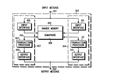
FIG. 1 shows a fault tolerant radio communication
system controller 100 which is able to maintain its
current process state in the event of a failure. That is
controller 100 is able to switch between parallel
2 0 processes, while maintainin~ current calls in progress,
after a primary processor experiences a fault. Controller
100 receives information from the rest of the radio
communication system in the form of input messages 101
and produces information for the rest of the syst~.l. in the
25 form o~;- output messages 102. An exampb of an input
message might be a request for a blk group call; while an
example of an output message mi~ht be a channel grant for
placin~ that call. Input messages 101 and output messages
102 are shown in FIG. 1 as separate entities, but might be
3 0 coupled together via a duplex, or half-duplex,
communication link. This arran~ement is commonly
employed, for example, in a so-called Ethernet~ link (i.e.,
IEEE 802.3 Local Area Ne~vork (LAN ).
5 6 6 PCI'/US93/05271-
Controller 100 includes two identical processors
103, 104, each bein~ connected to shared memory 105. In
a preferred embodiment, input messages 101 arrive at both
pr~cessors substantially simultaneously. Processors 103,
5 104 could be any of a wide variety of computers, but in the
preferred embodiment are two Delta Series computers (i.e.,
b.-ed on the Motorola MC68000 family of ~--icr~,~rocessors
and the VMEbus standard). Likewise, the shared memory
could be of any type compatible with the selected
10 processor, but a preferred implementation employs
reflective memory available from SYSTRAN Corporation as
part of the so-called SCRAMNetT~ Network. It should be
noted that the selection of processor (103, 104) and
shared, or reflective, memory (105) should be made to
l 5 provide electrical isolation between the two processors,
- such that electrical faults within one processor will not
affect the other. Processors 103, 104 are configured to
arbitrate among themselves, as later described, for the
ri~ht to enter input message 101 into-shared memory 105,
2 0 and for the right to ~enerate output m6ssages 102.
Processors 103, 104 thereby provide substantially
concurrent processin~ on input messa~es 101 in order to
enter it into shared memory 105. Once an input message
101 is effectively stored in shared memory 105,
2 5 processors 103, 104 will under~o subst~n~ially concurrent
processing to provide a val-~ output. Of course, only one of
the processors (103 or 104) will write a ~iven message to
shared memory, and only one will provide the requisite
output messages. In a preferred embodiment, the
3 0 arbitration schemes used to determine which processor
writes input messages 101 to shared memory 105, and
which provides output messa~es 102 are substantially
different, and hence are described separately.
... .... . ... ... .. .... ... .. . .... . ... ... . .. .. . . . . .. . . . . . . .
g4~00g2s 2 1 1 ~ 6 5 ~ PCI'/US93/05271
For purposes of further dcscribing the ou".ponents of
processors 103, 104, a single processor (103) wi!l be
described, as both processors are identical in this regard.
Processor 103 includes input interface 106 which receives
5 input mes~n~es 101 and manipulates a so-called
semaphore to gain exclusive access to a desi,3nat~ area of
shared memory 105. Once exclusive access has been
achieved, input interface 106 determines if input message
102 has already been stored, and if not, writes the input
l 0 communication messa~e to the shared memory. In a
pref~rred embodiment, input interfaces 106, 1 t 0 each
comprise hardware (e.~., Motorola VME 167 ~ingle board
computer) to~ether with sottware. Semaphore 108 resides
in a predetermined stora~e location of shared memory 105,
l 5 and provides for mutually exclusive access to shared
memory 105 by input interfaces 106, 1~0 and transaction
pr~.~sQrs 107, 111. Once it has exclusive use of shared
memory 105, input interface 106 searches a linked list
stored in shared memory 105, to determine whether the
2 0 current input message is presently stored in shared
memory (i.e., having already been written by the other
processor). If not, the input interface (with exclusive use)
would append the eurfent input message to the end of the
linked list. Subsequently, shared memory 105 is released
2 5 by -the input interface by modifying semaphore 108 in a
predeterminod fashion.
Proc&ssor 103 further includes output interface 109,
which provWes output messages 102, when enabled. As
described earlier, output messages 102 simply represent a
30 response to input message, and may take the form of a
channel assignment, busy indication, etc.
Lastly, processor 103 includes transaction processor
107, which oporat~s on the messages stored in shared
memory 105. While transaction processor 107 is capable
WO g4~00925 PCT/USg3~0S271,_
211~65~ 8
of directly reading input messa~e 102 from the linked list,
a preferred embodiment requires that transaction
processor 107 remove the message from the linked list
only after providing an output to output interface 109
SUpon completion access of this task, transaction proc~sor
107 then ~ains exclusive access to the linked list, via
semaphore 108. Since transaction processor 107 can read
the linked list as well as modify it by removing items,
transaction processor 107 requires a bi-directional link
10114 to shared memory 105, as shown.
Transaction processors 107, 111 additionally include
fault debction capability, which capability is well known
in the art. In a preferred embodiment, a fault is said to
have occurred when either pr~essor (103 or 104) fails to
lSproduce an output messa~e 102 from input message 101
within a predetermined time. Transaction processors 107
and 111 eaçh use shared memory 105, as later described,
to detect a fault on the opposin~ processor, thereby
determining which unit is pr~ently- providing output
; - 20messa~es 102 (i.e. which processor is enabled). It should
be noted that, though the foregoin~ description, as wel! as
a preferred embodiment, involves a two-procsssor
arrangement, it is recognized that allernate embodiments
mi~m employ more proce~sQrs.
25FIG. 2 shows a simplified flow diagram 200 depicting
the operation of a radio system controller, as it might be
embodied in pr~sssors 103, 104. Upon receipt of an input
message, the input is stored (201) in the shared memory.
(Note that process 201 is responsible for arbilr~ting the
30mutually exclusive use of the input message storage area
of shared memory, storing the messa~e only if not already
present, as later described.) Having succ~ssl,Jlly stored
- the message, the controller then processes (202) the
transaction. That is, the controller determines an
211~656
-'"O 94/00925 PCI'/US93/05271
appropriate response (i.e., output m~s~ ~e) for the
re~iv~l stimulus (i.e., input messa~e). As an example of
such a transaction, the controller mi~ht produce a channel
grant for talk-~roup ac~iv;t~r in response to a channel
S request (whkh request has been stored in shar~d memory).
Having determined an appropriate response, the controller
the determines (203) which of the two process~rs is
active, before the routine is exited (204). In addition to
fault detection, the foregoin~ determination routine is
10 necessary to ensure that the output is correctly produced,
and allows the input messa~e to be removed from the
linked list (recall that only the active processor is able to
do this). Active determination is a!so responsible for
fault detection and the change of status of which
15 processor is the one enabled to wrib the output.
FIG. 3 shows a detailed flow diagram depicting the
store input proc~ss (201) shown in FIG. 2. After an input
message is received (301), the active processor (which is
determined using process 203, as later described)
20 attempts to gain (302) exclusive access to shared memory.
This is accomplished usin~ a stora~e location in shared
memory, commonly referred to as a semaphore, to prohibit
access to the input m~-s~e stora~e area by other
processors. A preferred embodiment utilizes a semaphore
2 5 which provides for an insep;~rable read-modify-write
memory operation. For example, a processor instruction
~add one to a particular memory location~ provides that one
prc ssor read the location, modify the contents by addin~
one, and writ~ the modified contents back to the memory
3 0 location, while pr~v~nting other processQrs from reading
from, or writing to, memory. This approach represents but
a sampling of the many available semaphore techniques
which can be employed pursuant to this invention.
WO 94/00925 rCr/USg3tO527,~
211565 ~ l o
Once exclusive access is achieved, a doci;.ion (303)
is reached to detar...ine whether or not the current
message has already been stored in shared memory. Again,
there are many possible implementations, but a preferfed
embodiment provides that the controller scan the input
message area, comparing some predebrmined field of me
current input message (e.g., call identifier) with each of
the stored messages. If the current messa~e has not yet
been stored, the input messa~e is stored (304~ in shared
l 0 memory, before releasin~ (305) the shared memory
(modifying the semaphore). In a preferred embodiment, the
store operation involves adding the current message to the
tail of a linked list, and the memory is releassd by
subtracting one from the predetermined semaphore
l 5 memory location. By contrast, if the messa~e has already
been stored, the shared memory is released (305) and the
routine is exited (306).
FIG. 4 shows a detailed flow diagram depicffng the
active determination process (203) shown in FIG. 2, which
- 2 0 process is executed by each of the processors in the
system. In ~eneral, this routine is used to provide fault
detection, modify which processor is presently providin~
the output messages (active), and, based on the active
st~tus, determine whether or not to enable the ~ output
2 5 messa~e operation. After the transaction has been
processed, a timer is started (401), whîch timer value
r~presents an interval durin~ which a properly operating
processor is capable of producing an output. In a preferred
embodiment, the ~timer~ is represented by an operating
s~ste.-- call which returns a predetermined message after
the specified time (i.e., timer value). îf the timer has not
expired (e.~., no return message), the processors check
(403) to see if another (or, in a preferred embodiment, the
only other) processor's output is ready. This loop
211S65fi
'"O 94/0092~ PCI~/US93/05271
1 1
continues until either the timer expires (e.~., message
returned~, or another processor's output is ready.
Expiration of the timer indicates a fault in one of the
processors (e.~., not producin~ processed transactions),
S hence the fault indicator is set (405). The processor then
attempts to determine (406) whether or not it has active
st~tus, as later described.
By contrast, if another pr4ces~0r's output is ready
(403) before the timer expires, which case represents the
10 normal sequence when all (e.~., both) processors are
healthy, the timer is cancelled (404). A ~cision (406) is
then reached to determine whether or not the proc~ssor
has active status, e.~., as defined by a predetermined value
bein~ present in a predetermined memory location. If the
1 5 prsc~ssQr determines (e.g., by examining the predetermined
memory location) that it is not the active proc~ssor, the
routine is exited (408). If however, the i,-~icalion is that
the proces~Qr is the active one, the processors output is
enabled (407), which allows the processed tran~-ctien
20 results to flow to the output messa~e channel (102 shown
in FIG. 1). It shouW be noted that at this time, the input
message is re...oved from the input messa~e linked list in
shared memory, so that the same input is not ~rocessed
twice.
2 5 Thus, the present invention allows for an
implementation of a radio communication system
controller which uses ~eneral purpose computers coupled
together using a commercially available shared memory.
Each processor is able to operate under a readily available
3 0 operating system, and fault tolerance is achieved with
minimum~ impact on application software development.
Additionally, time delays after a fault are substantially
reduced, thus providin~ real-time outputs (i.e., without
- loss of current processing activity).