Note: Descriptions are shown in the official language in which they were submitted.
2115776
- 1 -
CAPTURE DISPLAY PACKAGE
BACKGROUND AND SIJMMARY
This invention relates to packaging, and more
particularly to a package for an elongated object such as
a flashlight in which at least a portion of the packaged
object is exposed.
Various packages are known in the prior art for
packaging of elongated objects, in which the package is
made up of a rear panel and a front panel which is folded
to define outwardly extending ribs, with the unfolded
portions of the front panel being secured to the rear
panel. An example of this construction is Cote U.S.
Patent 3,022,722; which illustrates upper and lower V-
shaped ribs. An opening is formed in the upper wall of
the lower rib, and a pair of aligned openings are formed
in the upper and lower walls of the upper rib, extending
rearwardly from the fold line of the upper rib. With
this construction, the package is assembled and trans-
formed to the location at which the object is to be
packaged, where the base of the object is placed through
the opening in the upper wall of the lower rib, and the
upper end of the object is "snapped" into the passage in
the upper rib defined by the aligned openings in the
upper and lower walls of the upper rib. This construc-
tion provides a package which generally functions satis-
factorily in retaining the object in position during
shipping, handling and display. However, it is possible
for the'object to be removed from the package during
display, simply by reversing the above steps carried out
in placing the object into the package.
It is an object of the present invention to
provide a folded-panel package for an elongated object,
such as a flashlight or the like, in which the object is
securely retained in engagement with the package in a
manner preventing the object from being removed from the
package without destroying the package. It is another
object of the invention to provide such a package in
. .. . ..._......_............
2115776
- 2 -
which a substantial portion of the object is exposed for
viewing by potential consumers. It is a further object
of the invention to provide a folded-panel package capa-
ble of packaging other objects alonq with the elongated
object, such as batteries and/or flashlights having a
different size and shape. Yet another object of the
invention is to provide a folded-pariel package which is
simple in its construction yet which provides highly
satisfactory performance in retainirig the objects in
engagement with the package after placement of the ob-
jects in the package.
In accordance with one aspect of the invention,
a package for an elongated object defining spaced first
and second ends includes a rear panel against which the
object is located, and a front panel secured 'to the rear
panel. A first outwardly extending rib is formed in the
front panel, and includes an opening for receiving and
engaging the object toward its first end. A second
outwardly extending rib is formed in the front panel, and
has an opening for receiving and engaging the object
toward its second end. The first and second ribs are
arranged such that at least a portion of the object
.{111 between its first and second ends is exposed therebe-
tween. The rear panel functions to retain the object
adjacent its first and second ends in engagement with the
first and second ribs, respectively, to maintain the
' object in the package. The first and second ribs are
each V-shaped, being formed by a pair of walls with a
fold line therebetween. The first and second ribs define
facing walls in which the openings in the first and
second ribs, respectively, are formed such that the edges
of the first and second ribs adjacent the openings engage
the object adjacent its first and second ends, respec-
tively. A third outwardly extending V-shaped rib may be
formed in the front panel. Like the first and second
ribs, the third rib is formed by a pair of walls with a
fold line therebetween. The second rib is located be-
..
5
2115776
- 3 -
tween the first and third ribs, and the second and third
ribs define facing walls with openings therein for re-
ceiving one or more second objects therein such that a
portion of each of the second objects between the second
and third ribs is exposed. As noted previously, the
first object may be a flashlight and the second object
may be one or more batteries for the flashlight. One end
of each of the first and second objects is enclosed by
the second rib, and the ends of the objects engage each
i 10 other to maintain the first and second objects in longi-
tudinal position within the package. The opposite end of
the second object is received within an opening formed in
a wall of the third rib.
In one form, the first end of the object in-
cludes a recess, and the opening formed in the first rib
is formed in the inner wall of the first rib in a manner
defining a cut-out flap, with the flap being engaged with
the recess in the first end of the object. This func-
tions to assist in retaining the object in engagement
with the first rib. The recess in the first end of the
object is defined by a lip, and the opening in the inner
wall of the first rib is formed so as to engage the lip.
In another form, the first end of the object
defines an external shoulder, e.g. a shoulder from which
the lip defining the recess extends. A first opening is
formed in the inner wall of the first rib through which
the object extends. A second opening is formed in the
outer wall of the first rib, and the second opening,is
configured so as to engage the shoulder defined by the
first end of the object to retain the object in position.
The invention further contemplates a method of
packaging an elongated object defining spaced first and
second ends. The method involves the steps of providing
a package including a pair of panels, and folding por-
tions of a first one of the panels to provide at least
first and second spaced ribs. Openings are formed in the
folded portions of the first panel, and the elongated
.
2115776
_ 4 -
object is placed into the openings. The ribs and the
openings are arranged such that the ribs engage the
spaced first and second end's of the object to prevent
outward movement of the object relative to the first
panel. The second panel is then secured to the unfolded
portions of the first panel to prevent movement of the
object in the opposite direction, for positively securing
the object within the package. The details of the method
are substantially in accordance with the foregoing summa-
ry.
Various other features, objects and advantages
of the invention will be made apparent from the following
description taken together with the drawings.
BRIEF DESCRIPTION OF THE DRAWINGS
The drawings illustrate the best mode presently
contemplated of carrying out the invention.
In the drawings:
Fig. 1 is an isometric view illustrating one
embodiment of a package constructed according to the
invention;
Fig. 2 is a plan view of a package blank from
+rv~ which the package of Fig. 1 is constructed;
Fig. 3 is a side elevation showing the package
blank of Fig. 2 folded for receiving the objects within
the folded ribs;
Fig. 4 is a section view taken along line 4-4
of Fig. 1;
Fig. 5 is a section view taken along line 5-5
of Fig. 1;
Fig. 6 is an isometric view similar to Fig. 1,
J showing another embodiment of the package of the inven-
tion; and
Fig. 7 is an isometric view similar to Figs. 1
and 6, showing yet another embodiment of the package of
the invention.
=;
:..~
'.~
2115776
_ 5 -
DETAILED DESCRIPTION OF THE INVENTION
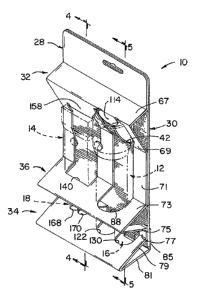
Fig. 1 illustrates a package 10 constructed
according to the invention for packaging a pair of elon-
gated objects such as a pair of flashlights 12, 14 and a
series of batteries 16, 18 for use with flashlights 12,
14, respectively. Referring briefly to Fig. 3, flash-
light 12 is a conventional flashlight having a cylindri-
cal handle 20 within which batteries 16 are adapted to be
received, and a head 22 housing a lens and a bulb. Head
22 defines an outwardly extending lip 24 which protects
the lens, and an angled section 26 is located between
handle 20 and head 22. Flashlight 14 is somewhat similar
in construction to flashlight 12, having a handle within
which batteries 18 are adapted to be received and a head
housing a bulb and a lens, and including an outwardly
extending lip for protecting the lens. However, the
handle and head of flashlight 14 are rectangular in
cross-section, and flashlight 14 has a shorter overall
length than that of flashlight 12. Batteries 16 are
conventional C-sized or D-sized cylindrical batteries,
and batteries 18 are conventional A-sized cylindrical
batteries.
As shown in Fig. 1, package 10 consists of a
front panel 28 and a rear panel 30. Portions of front
panel 28 are folded to define a series of ribs, generally
including an upper rib 32, a lower rib 34 and an interme-
diate rib 36.
Fig. 2 illustrates a blank from which package
10 is constructed. As shown in Fig. 2, the blank in-
cludes panels 28, 30, which are separated by a fold line
38.
Rear panel 30 is generally rectangular in plan,
having an opening 40 formed therein. Opening 40 is
defined by a semicircular edge 42 and a pair of parallel
side edges 44, 46. Rear panel 30 includes a tab 48,
defined by a pair of parallel edges 50, 52 and a trans-
verse edge 54 of opening 40. A pair of spaced end edges
2115776
- 6 -
56, 58 interconnect parallel edges 50, 52 and side edges
44, 46, respectively, of opening 40.
Rear panel 30 further includes a hang opening
60.
A series of transverse partial perforations or
fold lines are formed in front pane:L 28 including, from
top to bottom, a front side perforation 64 cooperating
with fold line 38 to define an upper wall 65 therebe-
tween, a rear side perforation 66 cooperating with per-
foration 64 to define a rib upper wall 67 therebetween, a
front side perforation 68 cooperating with perforation 66
to define a rib lower wall 69 therebetween, a front side
perforation 70 cooperating with perforation 68 to define
a central wall 71 therebetween, a rear side perforation
72 cooperating with perforation 70 to define a rib upper
wall 73 therebetween, a front side perforation 74 cooper-
ating with perforation 72 to define a rib lower wall 75
therebetween, a front side perforation 76 cooperating
with perforation 74 to define a lower wall 77 therebe-
tween, a rear side perforation 78 cooperating with perfo-
ration 76 to define a rib upper wall 79 therebetween, and
a front side perforation 80 cooperating with perforation
78 to define a rib lower wall 81 therebetween. A pair of
three-sided die cuts 82, 84 are formed along with front
side perforation 80. A flap 85 is defined between perfo-
ration 80 and the lower end of front panel 28.
Perforations 64, 66, 68, 70, 72, 74, 76 and 80
preferably extend only partially through front panel 28,
such that each front side perforation extends through
only a portion of the thickness of panel 28 leaving the
rear surface intact, and each rear side perforation
extends only partially through the thickness of panel 28
leaving the front surface intact.
A first opening 86 is formed in front panel 28.
Opening 86 extends from rear side perforation 66 past
front side perforation 70, encompassing walls 69 and 71,
and a portion of wall 73. Opening 86 includes a semi-
i
2115776
- 7 -
circular edge 88, the center point of which is approxi-
mately midway through the height of wall 73. A pair of
parallel side edges 90, 92 extend from semicircular edge
88, extending through wall 73 and the full height of wall
71, terminating at front side perforation 68. A pair of
divergent angled edges 94, 96 extend between parallel
side edges 90, 92, respectively, and a second pair of
parallel side edges 98, 100, respectively, formed in wall
69. Opening 86 is further defined by spaced, staggered
end edges 102, 104 and 106, 108 oriented parallel to rear
side perforation 66, with edges 106, 108 lying along rear
side perforation 66. Convergent angled edges 110, 112
extend between staggered end edges 102, 106 and 104, 108,
respectively.
A truncated circular tab 114 is defined between
the innermost points of end edges 106, 108, providing a
circular edge 116 extending therebetween. Tab 114 is
formed by a portion of the material of wall 69 which
remains after opening 86 is cut out in the manner de-
scribed. Tab 114 is adapted to bend rearwardly at rear
side perforation 66, which defines the truncated end of
tab 114.
A pair of oval openings 118, 120 are formed in
front panel 28 below opening 86. Oval opening 118 de-
fines semicircular end edges 122, 124 with a pair of
parallel side edges 126, 128, respectively, extending
therebetween. Similarly, oval opening 120 defines a pair
of semicircular end edges 130, 132, with a pair of paral-
lel side edges 134, 136, respectively, extending therebe-
tween. Oval openings 118, 120 are identical in construc-
tion, extending throughout wall 77 and partially through
walls 75, 79. Semicircular end edges 124, 132 define an
outermost point approximately midway through the height
of wall 75 above front side perforation 74, and semicir-
cular end edges 122, 130 are located an equal distance
below front side perforation 76.
2115776
_ 8 -
openings 86 and 40 in front and rear panels 28,
30, respectively, lie along a common longitudinal axis,
about which openings 118, 120 are symmetrical. That is,
the common longitudinal axis along which openings 86 and
40 lie is located midway between the longitudinal axes of
openings 118, 120.
A second opening 138 is formed in front panel
28 adjacent opening 86. Opening 138 is defined by a
transverse end edge 140, a pair of spaced parallel lower
side edges 142, 144, a pair of diverging angled edges
146, 148, a pair of spaced parallel upper side edges 150,
152, and a pair of convergent angled upper end side edges
154, 156. An upper tab 158 is defined by a transverse
upper edge 160 and oppositely oriented inverted L-shaped
edges extending between the opposite ends of edge 160 and
the upper ends of edges 154, 156. Opening 138 extends
throughout the height of wall 71, and partially through
wall 73 below front side perforation 70 and partially
through wall 69 above front side perforation 68.
A lower opening 162 is formed in front panel 28
adjacent openings 118, 120. Opening 162 consists of a
pair of parallel side edges 164, 166, the ends of which
are interconnected by scalloped lower arcuate edges 168,
170 and scalloped upper arcuate edges 172, 174. Opening
162 extends throughout wall 77 and a portion of each of
walls 75, 79, with edges 172, 174 and 168, 170 being
spaced an equal distance below and above front side
perforations 74, 76, respectively.
Openings 138, 162 lie along a common longitu-
dinal axis, which is spaced from and parallel to the
longitudinal axes of openings 40 and 86 and the axis of
symmetry of openings 118, 120.
To construct package 10, the blank of Fig. 2 is
first folded to its configuration illustrated in Fig. 3,
in which walls 67 and 69 cooperate to define upper V-
shaped rib 32, walls 79 and 81 cooperate to define lower
. .,
2115776
- 9 -
V-shaped rib 34, and walls 73, 75 cooperate to define
intermediate V-shaped rib 36.
Walls 65, 71 and 77 are not folded, such that
ribs 32, 34 and 36 extend outwardly therefrom. Walls 65,
71 and 77 lie in a common plane. Either before or after
folding the blank of Fig. 2 to its folded condition of
Fig. 3, an adhesive 176 is applied to the rear surface of
wall 65, an adhesive 178 is applied to the rear surface
of wall 71, an adhesive 180 is applied to the rear sur-
face of wall 77, and an adhesive 182 is applied to the
rear surface of flap 85. Alternatively, the adhesive
could be applied in corresponding locations on rear panel
30.
With the package blank of Fig. 2 in its folded
condition of Fig. 3, a pair of batteries 16 are placed
into openings 118, 120 in a manner as shown in Fig. 3,
wherein arcuate end walls 122, 124 and 130, 132 of open-
ings 118, 120, respectively, engage and cradle batteries
16 such that the longitudinal axes of batteries 16 are
substantially parallel to the plane of walls 65, 71 and
77. One end of each battery 16 is enclosed by lower rib
34, and the opposite end of each battery 16 is enclosed
by intermediate rib 36. A portion of each battery 16 is
exposed between walls 75, 79. Batteries 16 are prefera-
bly placed into the position of Fig. 3 utilizing rear-to-
front movement of batteries 16 so as to bring the side
wall of each battery 16 into engagement with arcuate end
walls 122, 124 and 130, 132 of openings 118, 120, respec-
tively.
Either before or after placement of batteries
16, flashlight 12 is placed into its Fig. 3 position.
This is preferably done by moving flashlight 12 in a
rear-to-front direction into opening 86. The butt end of
flashlight 12 passes through the lower portion of opening
86 such that the lower end of flashlight handle 20 engag-
es curved.end wall 88 and the remainder of handle 20
passes between side edges 90, 92 of opening 86. The head
2115776
- 10 -
end of flashlight 12 is moved in a rear-to-front direc-
tion such that flashlight head 22 is positioned within
the upper end of opening 86 between walls 98, 100. Lip
24 of flashlight head 22 is received within the narrow
spaces between upper converging edges 110, 112 of opening
86 and the adjacent portion of tab edge 116. Edges 110,
112 and 116 engage the inner and outer surfaces of lip
24, and staggered edges 106, 108 engage the end of lip 24
at spaced locations. Simultaneously, truncated circular
tab 114 is pivoted clockwise about rear side perforation
66 and held in position and, after flashlight 12 is in
its Fig. 3 position, is returned to its Fig. 3 position
so as to engage the inner edge of lip 24, and the end of
tab 114 opposite rear side perforation 66 is engaged
within the recess defined by lip 24 with the lens of
flashlight 12. This functions to retain flashlight 12 in
its Fig. 3 position, wherein the butt end of flashlight
12 is enclosed within intermediate rib 36 and the head
end of flashlight 12 is engaged by tab 114 and the edges
of opening 86 in wall 69 of rib 32. The upper end of
opening 86 is configured such that the distance between
convergent angled edges 110, 112 is less than the diame-
ter of lip 24, to allow only a small portion of lip 24 to
project outwardly from the fold of upper rib 32.
With flashlight 12 in its Fig. 3 position, the
:.; longitudinal axis of flashlight 12 is parallel to the
longitudinal axes of batteries 16 and to the plane of
walls 65, 71 and 77. A portion of flashlight head 22
extends above walls 65, 71 and 77.
Flashlight 14 is placed into opening 138 in a
manner similar to that described with respect to flash-
light 12, such that its butt end is engaged with and
cradled by transverse end wall 140 of opening 138 and its
head end is engaged within the upper portion of opening
138 between side edges 150, 152. Flashlight 14 includes
,.F an outwardly projecting lip like lip 24 of flashlight 12,
which is received within the spaced upper ends of opening
2115776
-- 11 -
138 between tab 160. Tab 160 extends into the recess
defined by the lip of flashlight 14, such that transverse
upper edge 160 of tab 158 engages the lens of flashlight
14 and the inner surface of the lip of flashlight 14. In
this manner, flashlight 14 is retained in a position in
which its longitudinal axis is orierited parallel to the
plane of walls 65, 71 and 77. Batteries 18 are placed
into opening 162 in a side-by-side manner, being engaged
and cradled by arcuate edges 168, 170, 172 and 174 of
opening 162. Batteries 18 are thus maintained in a
position like that of batteries 16, in which their longi-
tudinal axes are oriented parallel to the plane of walls
65, 71 and 77.
As with flashlight 12 and batteries 16, the
butt end of flashlight 14 is enclosed by rib 36, and is
engaged with the upper ends of batteries 18 within rib
{ 36. The opposite ends of batteries 18 are enclosed
within rib 34. The portion of batteries 18 between ribs
34 and 36 is exposed, as is the portion of flashlight 14
between ribs 32 and 36.
With flashlights 12, 14 and batteries 16, 18
positioned in the manner described, rear panel 30 is
folded onto front panel 28 in the direction of arrow 184
(Fig. 3), such that the portions of rear panel 30 facing
the rear surfaces of unfolded walls 65, 71 and 77 engages
adhesive areas 176, 178 and 180 to adhere rear panel 30
and front panel 28 together. Flap 85 is then folded over
{ the outer edge of rear panel 30 in the direction of arrow
186 (Fig. 3) such that adhesive 182 on its rear surface
engages the rear surface of rear panel 30. Upon such
folding of flap 85, cut-outs 82, 84 form a pair of feet
188, 190 (Figs. 4, 5, respectively).
Upon folding of rear flap 30 as described, the
rear portion of flashlight head 22 is received within
opening 40 in rear panel 30, so as to extend therethrough
in a manner as illustrated in Fig. 5. Tab 48 defined by
opening 40 in rear flap 30 is forced over lip 24 of
,, .
2115776
- 12 -
flashlight head 22, such that the opposite ends of its
edge 54 engage the inner surface of lip 24 at a pair of
spaced locations. This functions to assist truncated
circular flap 114 and edges 110, 112 of opening 86 in
retaining flashlight 12 in its Fig. 5 position.
As shown in Figs. 4 and 5, the positioning of
rear flap 30 against front flap 28 functions to capture
flashlights 12, 14 within ribs 32, 36 and batteries 16,
18 within ribs 34, 36. Flashlights 12, 14 and batteries
16, 18 are captured in a manner preventing their removal
from package 10 in a rear-to-front direction without
destroying at least a portion of package 10, while expos-
ing a substantial portion of the length of flashlights
12, 14 and batteries 16, 18 for allowing the potential
purchaser to view and touch such articles prior =to pur-
chase.
As noted previously, the lower ends of batter-
ies 16, 18 are engaged with the inner surface of wall 81
defining lower rib 34. The upper end of flashlight 12 is
engaged with edges 106, 108 of opening 86, and likewise
the upper end of flashlight 14 is engaged with the upper
transverse edges of opening 138 adjacent angled edges
154, 156. The upper ends of batteries 16, 18 engage the
butt ends of flashlights 12, 14, respectively within the
interior of rib 36, to maintain flashlights 12, 14 and
~ batteries 16, 18 in longitudinal position within package
..
10.
When rear panel 30 is folded onto front panel
28, hang opening 60 in rear panel 30 comes into alignment
with a similarly configured hang opening 191 (Fig. 2)
formed in front panel upper wall 65. For display purpos-
es, package 10 can either be hung by a hook extending
through hang openings 60 and 191 or alternatively can be
stood upright as shown in Figs. 4 and 5, wherein feet
188, 190 and the outer end of lower rib 34 function to
support package 10 in a substantially vertical position.
2115776
13 -
Fig. 6 illustrates an alternate embodiment for
a package 194 constructed according to the invention.
This embodiment is nearly identical in all respects to
the portion of package 10 which functions to package
flashlight 12 and its batteries 16, as shown and de-
scribed with respect to Figs. 1-5. Like reference char-
acters are shown in Fig. 6 for clarity in understanding.
Fig. 7 illustrates another embodiment of a
package 198 constructed according to the invention.
Package 198 provides a package construction for packaging
a pair of differently sized flashlights 12, 12a and a
flashlight 14 therebetween. Generally, package 198
consists of a front panel 200 and a.rear panel 202,
secured together in substantially the same manner as
!~~ 15 described with respect to front and rear panels 28, 30 of
~.i
package 10. Front panel 200 of package 198 is formed to
provide an upper rib 204 defined by a pair of walls 206,
208, a lower rib 210 formed by a pair of walls 212, 214,
and an intermediate rib 216 defined by a pair of walls
218, 220. The unfolded portions of front panel 28 be-
tween ribs 204, 210 and 216 are adhered to rear panel 202
using adhesive or the like, in the same manner as de-
scribed with respect to package 10.
Flashlight 14 and its batteries 18 are engaged
and secured within package 198 in the same manner as
described with respect to package 10 of Figs. 1-5.
Flashlights 12, 12a are retained in position in
package 198 in a different manner than that of package 10
of Figs. 1-5. In the Fig. 7 embodiment, the butt ends of
flashlights 12, 12a are engaged with the upper surface of
wall 212 of lower rib 210. Aligned circular openings are
formed in walls 218, 220 of intermediate rib 216, through
which the lower end of handle 20 of each flashlight 12
extends. Similarly, an elliptical opening is formed in
lower wall 208 of rib 204, and a circular opening is
formed in upper wall 206 of rib 204. When package 198 is
in its assembled condition of Fig. 7, the openings in
-~ a
:'a
2115776
- 14 -
walls 206, 208 of upper rib 204 and in walls 218, 220 of
intermediate rib 216 lie along a common axis. Lip 24
defined by the outer end of flashlight head 22 extends
through the circular opening formed in upper wall 206 of
upper rib 204. With this construction, flashlights 12,
12a are positively retained within package 198 against
frontward-rearward movement by engagement of flashlight
handle 20 with intermediate rib 216 and engagement of
flashlight head 22 with upper rib 204. Longitudinal
movement of flashlights 12, 12a is prevented by engage-
ment of the butt end of flashlights 12, 12a with the
upper surface of lower rib upper wall 212 and engagement
of the shoulder from which lip 24 extends with the inner
surface of upper rib upper wall 206.
In order to insert each of flashlights 12, 12a
into the package of Fig. 7, handle 20 of each flashlight
must first be inserted in a longitudinal direction
through the elliptical opening formed in wall 208 of
' upper rib 204, and then through the aligned circular
openings formed in walls 218, 220 of intermediate rib 216
until the butt ends of flashlights 12, 12a engage upper
wall 212 of lower rib 210. Thereafter, upper wall 206 of
upper rib 204 is folded to its Fig. 7 position, such that
lip 24 extends through the circular opening formed in
wall 206. Rear panel 202 is then adhered to the unfolded
walls of front panel 200.
It is understood that the construction of
package 198 for packagingflashlights 12, 12a could be
employed in a single package in which one flashlight is
packaged, either by itself or with its associated batter-
ies 14. Likewise, it is understood that the same con-
struction of upper rib 32 of package 10 could be used in
the package of Fig. 7, with the lower end of flashlight
12 being retained in the same manner as the package of
Fig. 7.
Other similarly constructed packages for dis-
playing any other elongated object, or combination of ob-
:':~
2115776
- 15 -
jects such as flashlights with or without batteries, are
contemplated as being within the scope of the present
invention.
Various alternatives and embodiments are con-
templated as being within the scope of the following
claims particularly pointing out and distinctly claiming
the subject matter regarded as the invention.
:.~
N{ .. . ~
,.~
?:;l