Language selection

Search

Patent 2116059 Summary

Third-party information liability

Some of the information on this Web page has been provided by external sources. The Government of Canada is not responsible for the accuracy, reliability or currency of the information supplied by external sources. Users wishing to rely upon this information should consult directly with the source of the information. Content provided by external sources is not subject to official languages, privacy and accessibility requirements.

Claims and Abstract availability

Any discrepancies in the text and image of the Claims and Abstract are due to differing posting times. Text of the Claims and Abstract are posted:

  • At the time the application is open to public inspection;
  • At the time of issue of the patent (grant).
(12) Patent: (11) CA 2116059
(54) English Title: GOLF CLUB GUIDE DEVICE
(54) French Title: DISPOSITIF DE GUIDAGE DE BATON DE GOLF
Status: Deemed expired
Bibliographic Data
Abstracts

English Abstract


The invention relates to a golf training aid to be used
in combination with a golf club to assist in the visualizing
of the action of the golf club head during the arc of a golf
swing. The training aid is adapted to be attached to the
shaft of the golf club so as to maintain the club head in the
proper position during the arc of a swing. The device
includes a body block and attachment portion for removable
securement to a golf club shaft by sliding gate and lock
means. The body block has a flat surface and is positioned at
90° to the golf club head, acting as a level to help maintain
the club head in a proper position throughout the arc of a
golf club swing, thereby maintaining the club head in a proper
position for striking a golf ball. A rubber plug secures the
attachment means to the golf club so as to prevent slipping or
movement of the training aid during a golf club swing.


French Abstract

Dispositif de guidage à utiliser avec un bâton de golf pour aider à visualiser le déplacement de la tête du bâton pendant l'arc d'un swing de golf. Le dispositif est adapté pour être fixé au manche du bâton de façon à maintenir la tête dans la position appropriée durant l'arc d'un swing. Le dispositif comprend un corps et une partie de fixation pour une fixation non permanente à un manche de bâton de golf en coulissant un dispositif de fermeture et de verrou. Le corps comprend une surface plane et est placé à 90 degrés de la tête du bâton de golf, agissant comme un niveau pour faciliter le maintien de la tête du bâton dans une position appropriée durant l'arc d'un swing d'un bâton, maintenant ainsi la tête dans une position appropriée à frapper la balle de golf. Un bouchon en caoutchouc fixe le dispositif de fixation au bâton de golf de façon à empêcher le glissement ou le déplacement du dispositif de guidage pendant un swing d'un bâton de golf.

Claims

Note: Claims are shown in the official language in which they were submitted.

THE EMBODIMENTS OF THE INVENTION IN WHICH AN EXCLUSIVE
PROPERTY OR PRIVILEGE IS CLAIMED ARE DEFINED AS FOLLOWS:

1. A golf swing training device for providing a visual means for visualizing a golf
swing arc comprising:
a base member;
a shaft engaging jaw pivotally secured to said base member, said base member
and said shaft engaging jaw forming between them a passageway adapted to receiveand hold a golf club shaft;
locking means to secure said base member and said shaft engaging jaw in a
closed position about said golf club shaft; and a resilient friction member adapted to be
received between said golf club shaft and said shaft engaging jaw when the device is in
use; and
wherein the locking means comprises a jaw retainer adapted to be slidably
received by said base member and shaft engaging jaw and adapted to hold said base
member and shaft engaging jaw in the closed position about said golf club shaft.

2. The device of claim 1 further comprising means for securing the jaw retainer in
contact with the base member and shaft engaging jaw.

3. A golf swing training device for providing a visual means for visualizing a golf
swing arc comprising:
a base member;
a shaft engaging jaw pivotally secured to said base member, said base member
and said shaft engaging jaw forming between them a passageway adapted to receiveand hold a golf club shaft;
locking means to secure said base member and said shaft engaging jaw in a
closed position about said golf club shaft; and a resilient friction member adapted to be
received between said golf club shaft and said shaft engaging jaw when the device is in
use; and
wherein the base member includes a flat surface acting as the means for
visualizing.


4. The device of claim 3 wherein the golf club shaft is generally parallel to the flat
surface when the base member and the engaging jaw are in the closed position about
the golf club shaft.

5. The device of claim 3 wherein the flat surface is generally square.

Description

Note: Descriptions are shown in the official language in which they were submitted.


~ 2l~n~s
GOLF SWING TRAINING AID

FIBLD OF THE INVENTION

This invention relates to a golf aid and more
particularly to an aid to improve a golfer's swing.

BACRGROUND OF THE INVENTION

This invention relates to a golf swing training aid
adapted to work as a level which is removably secured to the
shaft of a golf club, thereby providing a golfer with a means
of visualizing the club face and thereby maintaining the club
face in a proper position during the arc of a golf swing for
striking a golf ball.

A number of patents have addressed the problem of
maintaining a golf club head in a proper position during the
arc of a swing for striking of a golf ball. U.S. patents nos.
4,953,867 and 4,949,971 are addressed to the problem of
aligning a putting stroke. U.S. patents nos. 5,178,394 and
3,680,870 teach weight devices adapted to be attached to a
golf club shaft to assist in balancing of a golf club during a
swing. U.S. patent no. 3,360,268 teaches a device adapted to
be attached to a golf club head to assist in maintaining the
proper golf head direction.

The device of the present invention is adapted to be
removably fastened to the shaft of a golf club, thereby
providing the golfer with a means of visualizing the
orientation of a golf club face and thereby assisting in
maintaining the golf club face in a proper position during the
stroke attitude for striking a golf ball "head-on". The
device can be used during practice swings to improve a
golfer's swing arc thereby improving the golfer's contact with
the golf ball.

2116059


The device is capable of being attached to the shaft of
either an iron or wood golf club. It can be conveniently
carried in a golfer's pocket or a golf bag when not in use.

~UNMARY OF THB INVENTION

The device of this invention relates to a golf swing
training aid, for providing a visual means for properly
aligning a golf stroke attitude and golf swing arc, comprising
a main body block, a locking assembly for removable securement
of the training aid to a golf club shaft, said body block
comprising a flat usually forward facing surface, positioned
so as to be at a 90~ angle to the ball striking surface of a
golf club head.
BRIEF DE~CRIPTION OF THB DRAWING8

The invention is illustrated by way of example in the
accompanying drawings in which:
Figure 1 shows a perspective plan view;
Figure 2 shows a perspective rear view;
Figure 3 shows a perspective side view;
Figure 4 shows a perspective front view;
Figure 5 shows an exploded perspective view of the golf
training aid; and
Figure 6 shows a perspective view of the golf training
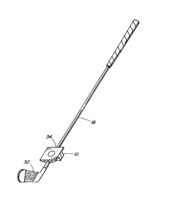
aid attached to an iron golf club for use.

DBTAILED DESCRIPTION OF THE PK~Kn~v EMBODINENT

The training aid device assembly comprises a base member
10 and a shaft engaging jaw 12 secured to each other by a
pivot pin 14 at the rear most end of the jaw 12. The base
member and jaw 12 define between them a passage way 16 adapted
to receive and hold a golf club shaft 18. Grooves 19 extend

. - ~ 3 ~ ~ ~ ~6~

at right angle to the passage way 16 in the base member 10. A
resilient friction member 20 is adapted to be received between
the golf club shaft 18 and the jaw 12 and inhibits sliding of
the shaft 18 within the passage way 16 relative to the base
member 10 and the jaw 12. Channels 22 are provided in both
side edges of the jaw 12. A jaw retainer 24 slidably engages
the channels 22 of the jaw 12 to prevent opening of the jaw
12. A jaw retainer locking member 26 slides within a channel
36 provided on the upper face of the jaw retainer 24 and into
a notch 28 provided in one of the side edges of the jaw 12
thereby ensuring the proper positioning of the jaw retainer 24
relative to the jaw 12. A second locking member 30 is adapted
to be secured to the jaw 12 thereby restricting movement of the
jaw retainer 24 together with the jaw retainer locking member 26
once they have been properly positioned, in particular preventing
movement of the training aid device during the execution of a
golf swing.

In use, the base member 10 is pivotally secured to the
shaft engaging jaw 12 by means of the pivot pin 14. The golf
club shaft 18 is placed within the passage way 16. The base
member 10 is positioned on the golf club shaft 18 so that it
is at 90~ with the club face 32. If the user so desires marks
can be made on the golf club shaft 18 opposite the arrow tabs
34 on either side of the base member 10 so that the aid can be
secured again to the golf club without having to make any
visual adjustment of the positioning of the base member 10
relative to the club face 32. The resilient friction member
20 is then placed between the shaft engaging jaw 12 and the
golf club shaft 18 to prevent movement of the golf club shaft
18 relative to the base member 10 and jaw 12 assembly. The
jaw retainer 24 is then slid into the channels 22 of the jaw
12 as well as the grooves 19 of the base member 10. The jaw
retainer locking member 26 is then slid into a channel 36
provided in the upper surface of the jaw retainer 24 and slid
within the aperture 28 provided in the upper face of the jaw


~3

- 211~~59

- 4 -

12. The second locking member 30 is then secured into place
in the jaw 12. The device is then ready for use.

In a preferred embodiment, the base member 10 and the
shaft engaging jaw 12 are made of a suitable and durable
material such as plastic while the resilient friction member
20 is made of rubber or any other suitably resilient material
providing the necessary friction.

While the present invention has been described in
connection with a specific embodiment thereof and in a
specific use, various modifications will occur to those
skilled in the art without departing from the spirit and scope
of the invention as set forth in the appended claims. I
therefore wish to embody within the scope of the patent which
may be granted hereon all such embodiment as reasonably and
properly come within the scope of my contribution to the art.


r~ ~

Representative Drawing
A single figure which represents the drawing illustrating the invention.
Administrative Status

For a clearer understanding of the status of the application/patent presented on this page, the site Disclaimer , as well as the definitions for Patent , Administrative Status , Maintenance Fee  and Payment History  should be consulted.

Administrative Status

Title Date
Forecasted Issue Date 1999-01-05
(22) Filed 1994-02-21
Examination Requested 1994-03-18
(41) Open to Public Inspection 1995-08-22
(45) Issued 1999-01-05
Deemed Expired 2003-02-21

Abandonment History

There is no abandonment history.

Payment History

Fee Type Anniversary Year Due Date Amount Paid Paid Date
Application Fee $0.00 1994-02-21
Maintenance Fee - Application - New Act 2 1996-02-21 $50.00 1996-01-31
Maintenance Fee - Application - New Act 3 1997-02-21 $50.00 1997-02-12
Maintenance Fee - Application - New Act 4 1998-02-23 $50.00 1997-12-18
Final Fee $150.00 1998-08-25
Maintenance Fee - Patent - New Act 5 1999-02-22 $75.00 1999-02-09
Maintenance Fee - Patent - New Act 6 2000-02-21 $75.00 2000-02-07
Maintenance Fee - Patent - New Act 7 2001-02-21 $75.00 2001-02-20
Owners on Record

Note: Records showing the ownership history in alphabetical order.

Current Owners on Record
LEVESQUE, CLAUDE A.
Past Owners on Record
None
Past Owners that do not appear in the "Owners on Record" listing will appear in other documentation within the application.
Documents

To view selected files, please enter reCAPTCHA code :


To view images, click a link in the Document Description column. To download the documents, select one or more checkboxes in the first column and then click the "Download Selected in PDF format (Zip Archive)" or the "Download Selected as Single PDF" button.

List of published and non-published patent-specific documents on the CPD .

If you have any difficulty accessing content, you can call the Client Service Centre at 1-866-997-1936 or send them an e-mail at CIPO Client Service Centre.


Document
Description 
Date
(yyyy-mm-dd) 
Number of pages   Size of Image (KB) 
Cover Page 1999-01-04 1 47
Claims 1998-05-06 2 52
Description 1998-05-06 4 158
Cover Page 1995-10-16 1 14
Abstract 1995-08-22 1 25
Description 1995-08-22 4 161
Claims 1995-08-22 1 32
Drawings 1995-08-22 3 54
Representative Drawing 1999-01-04 1 3
Representative Drawing 1998-05-20 1 6
Correspondence 1998-08-25 2 55
Fees 2001-02-20 1 30
Fees 2000-02-07 1 32
Fees 1999-02-09 1 35
Prosecution Correspondence 1994-03-18 1 29
Office Letter 1994-08-12 1 56
Correspondence Related to Formalities 1998-08-25 2 57
Prosecution Correspondence 1998-01-19 2 60
Examiner Requisition 1997-08-01 2 37
Prosecution Correspondence 1994-05-02 1 31
Fees 1997-12-18 1 36
Fees 1997-02-12 1 41
Fees 1996-01-31 1 45