Note: Descriptions are shown in the official language in which they were submitted.
r~~ 9~ro4~za ~~rr~s9zro7o~~
.~. .a. t.~ . t ~D ~-
F~'~HO13 AND ~1PPAF~"rtTS FOR GOI~TTP,~LLTNG
~ FUME HpOD
Field of tine Tnvention:
this invention relates ~to laboratory fume hood
controllers end more spec~.fically to methods and
apparatus for varying a fume hood's face velocity in
response to variations in o;ne pr mora hood
containment affecting conditions.
~ackground of the Invention:
p laboratory fume hood-is a ventilated enclosure
where harmful materials can be handled safely. ~'he
hood captures contaminants and prevents them from
escaping into the laboratory by using an exhaust
blower to draw air and contaminants an and around
~he'hood's work era away from the operator so that
inhalation of and contact with the contaminants are
minimised. Access to the interior of the hood is
~hrough'.~n opening which is closed with a sash which
typically slides up and down to vary the opening
~.nto the hood .
'1~0 93/04324 PCT/US92/0705.
., ,
. ~ ... _.. ,~ .~ z~ ._
The velocity of the air flow through the hood
opening is called the f ace velocity. The more
hazardous the material being handled, the higher the
recommended f ace velocity, and guidelines have been
established relating face velocity to texicity.
Typical face velocities for laboratory fume hoods
are s0 to 150 feet per minute (fpm), depending upon
the application.
When an operator is working in the hood, the
sash is opened to allow free access to the materials
inside. The sash may be opened partially or fully,
depending on the operations to be performed in the
hood. While fume hood and sash sues vary, the
opening provided by a fully opened sash is on the
order of ten square feet. Thus the maximum air flow
which the blower mush provide is typically on the
order of 600 to 1500 cubic feet per minute (cfm).
The sash is closed when the hood is not being
used by an operator. Tt is common to store
hazardous materials inside the hood when the hood is
not in use, and a positive airflow must therefore be
maintained to exhaust contaminants from such
materials even when the hood is not in use and the
sash is closed. As the hazard level of the
mater~.als being handled and the resulting minimum
face vel~city increases. maintaining a safe.face
-velocity'becomes more difficult.
w~ 9moa~~a ~criu~9as~~os7
a t i ~ f 1 )
i n
.. .~. a. ,.%
An important consideration in the design of a
fume hood system is the cost of running the system.
There are three major areas of costs: the capital
expenditure of installing the hood, the cost of
power to operate the hood exhaust blower, and the
cost of heating, cooling, and delivering the
"make-up air,~~ which replaces the air exhausted from
the room by the fume hood. ~'or a hood operating
continuously with an opening of 10 square feet and a
f act velocity of 100 fpm, the cost of heating and
cooling the make-~up air could, for example, run as
high as fifteen hundred dol7.ars per year in the
northeastern United Mates. WThere chemical work is
done, large numbers df fume hoods may be required.
For example, the Massachusetts s Institute of
Technology has approximately 550 fume hoods, most of
which are in operation 24 he>urs a day.
capital or investment costs is an important
~aCtor an the design ~f fume hood systems. This
elates to the capital cost o~ the supply and
exhaust fans, duct-work, boiler and cha.llers, and
other equipment related to the movement and
conditioning of the outside air brought into and
exhausted from the building through the fume hoods.
The laze, capacity arid cost of this equipment is
integrally related to the peak capacity of air
'volume~to be exhausted from the hoods. This total
volume is in turn directly related to the face
" , ,.., '. :' ". . . , , ~. ." . .
VSr~ 93/04324 .:, y ~. ; y, , : , ~, P~'i'/LJS92/0705
~i
velocities of those hoods. For example, a 20%
reduction in the face velocity for which. the
building hoods are designed, from 1~0 FPM to 8o FPM
allows for a 20g reduction in the required capacity
of the system air handling equipment.
Consequently, there are strong economic reasons
for using the lowest face velocity which still
produces acceptable fume hood capture and
containment. P2uch research has been performed
recently on the factors affecting this minimum
acceptable face vel~cz,ty. For example, with a fume
hood having no equipment in the first ~" back from
the sash, uniform face velocity distribution across
the face of the ho~d, and no high cross drafts, the
face v~locit~ can be set to 60 FPM and excellent
containment will occur. I~owever, spip age will
occur at 60 FPM if people walk past the hood,
someone waves their arms near the opening or supply
air diffusers blow air past the corners in front of
the hood. All these disturbances create cross
drafts and challenges to the fume hood containment
which can pull fumes out of the hood. Tncreasing
the face velocity to 100 or 125 FPM significantly
reduces the spillage caused by these factars. Above
1.5.~ FPM, the air flow into the hood can became
turbulent creating eddy currents and local low
~~
pressure'areas which can also create spillage.
WO 931Oa132~1 PC'f/LJS92/07057
. ~ .,
y l
° Because of the above factors, many laboratories
operate their hoods at 100 to 125 FPM. Others allow
the face velocities to drop to 70 to ~0 FPM when the
laboratories are unoccupied and operators are not
near the hood where they might create crossdrafts
from their motions. A very few companies operate
their hoods at 60 FPM, but only with strict
operating guidelines in order to prevent disturbance
of the fume hood's containment.
Tn order to save energy and reduce the peak air
capacity in laboratories, fLlme hood control systems
are presently used that maintain a constant face
velocity independent of the sash opening. Ea~ly
~e~~ions of these systems ~~~raced by changing _
volume in a two or three st~,p operation based on the
sash heig:~,t or the amount of: sash opening. Much
better and more recent syst~ms,provide can~inuous
control caf the air vol~xne based on sash position and
are referred to as variable air volume systems. An~
e~ampl~ of one of these systems is described in U.S.
Pa°ten~s 4,528,98 and 4,706.55. These systems work
weld., but aye dependent on the operator lowering the
sash. When 'the c~pers.tor dines lower the sash, the
exhaust, and typically also the room supply air
volume; are reduced proportionately which generates
i the energx savings. If many hoods are used an a
~.
v~uildi:ng'wi~h these controls, both the average and
typical peak total a~.r volumes will be reduced due
W~ 93/0434 G.) '~ ,-~ ~ ~ '~ ~ ~'Cl'/IJS9~/0705~
to the diversity in the hood's operation. Tn other
words, it is unlikely that all the hoods will be
fully open at any one time. A problem for the
building designer, however, is in estimating how
much diversity will actually occur in the building.
Consequently, many designers take a worst case view
and don't size the buildings capacity below ar much
below the 100% capacity assumption of all the hoods
full open at the same time. This is done because
the designer is concerned that the users will not
lower the sash when leaving the hood area. This is
unfortunate because studies have shown that
operators spend only a small fraction of their time
in front of the hood.
Tn an attempt to bypass the operator problem of
not closing sashes some fume hood manufacturers have
introduced devices such as ;>hown in U.S. Patent
4,774,~7~ that detect the presence of the operator
in front of the hood and raise the sash to some
preset position. When the operator moves away from
the hood, the sash is automatically closed.
Typically, a two state or variable air volume
control system is also used to vary the air volumes
to maintain a constant face velocity at the two
different sash positions.
These sash operator systems have not as of yet
_~
.received~widespread acceptance among researchers for
several reasons. Firstly, the rapid movement of the
wo ~~ioa3za ~orius9zio7as~
r
~- ..L .
- 7 _
sash up and down can occur even when a person just
walks past the hood, producing a disturbing f else
reaction of the hood. Also, many researchers like
to operate the sash at various heights, and this is
made more difficult by the two position operators.
Further, many hoods have wires, tubes and small
hoses going into the hood near the bottam of the
sash opening. Uncontrolled movement of the sash
might hit these wares and hoses and potentially tap
over delicate glassware to which the tubes and hoses
are connected. This in turn could create a serious
and potentially dangerous accident. Lastly, many
hoods have horizontally rnov'.ng sashes which make at
difficult to implement a sysctem to move the sashes
iz~ oxder to increase or decrease the amount of hood
opening.
For all of the above reasons, a better approach
is needed for reducing both energy usage and peak
estimated replacement volume while not creating a
potential hazard and not adversely affecting the
researcher's work.
Summary of the Invention
din object of this invention is to provide an
improved methad and apparatus for controlling a fume
hood, which controller (a) substantially reduces the
replacement azr utilized by the system, regardless
of 'sash position, (b) permits fume hood systems to
be designed for lower peak volume flow without
CA 02116134 1999-04-19
g _
permitting or creating any danger of a breakdown in
toxic fume containment or any danger of damage to
ongoing experiments or equipment, and (c) permits
researchers complete flexibility in selecting sash
positions.
The present invention provides a controller
for use with a fume hood having face velocity control
means, the controller comprising means for detecting
changes in at least one containment affecting
~o condition; and change means responsive to the
detecting means detecting a selected change in
containment affecting condition for causing the
control means to make a corresponding change in the
face velocity of the fume hood to a preselected
velocity for the changed containment condition, the
change means including incrementing means responsive
to a detection by the means for detecting of a
selected increase in a selected containment affecting
condition for causing the control means to increase
2o the face velocity of the fume hood to a selected
increased level, and decrementing means responsive to
detection by the means for detecting of a selected
reduction in a containment affecting condition for
causing the control means to reduce the face velocity
of the fume hood to a selected decreased level.
In another aspect of the present invention,
there is provided a method for controlling a fume hood
having face velocity control means comprising the
steps of detecting changes in at least one contain-
3o ment affecting condition; and causing the control
means to make a corresponding change in the face
velocity of the fume hood in response to a detected
change in containment affecting condition to a
CA 02116134 1999-04-19
- 8a -
preselected velocity for the changed containment
condition, the change causing step including the steps
of causing the control means to increase the face
velocity of the fume hood to a selected increased
level in response to the detection during the
detecting step of the occurrence of a selected
containment affecting condition, and causing the
control means to reduce the face velocity of the fume
hood to a selected decreased level in response to the
~o detection of a selected reduction in a containment
affecting condition.
More specifically, this invention provides a
controller for use with a fume hood having a face
velocity control. The face velocity control may
control face velocity directly or may control it
indirectly by controlling flow volume or some other
conditions affecting face velocity. The controller
has a detector for detecting at least one containment
affecting condition, which condition may be (a) the
2o presence or proximity of a person within a
predetermined area of the fume hood, (b) movement
within a predetermined area of the fume hood, either
by a person or as a result of air drafts or other
conditions, and/or (c) the presence of equipment or
material within a predetermined distance from the
front of the hood. Appropriate detectors are provided
for each condition to be detected. In response to the
detector detecting a selected change in containment
affecting conditions, the face velocity control makes
so a corresponding change in the face velocity of the
fume hood to a preselected velocity which is
appropriate for the changed containment condition.
CA 02116134 1999-04-19
- 8b -
The change may be an increase in the face velocity of
the fume hood to a
'1~0 93/14324 ~G I'/~....IS92/~7057
:'.~ _. .;. ~ .
_ g _
level sufficient to assure containment of fumes in
the hood with the containment affecting condition
present, or the change may be a reduction in the
face velocity of the fume hood to a selected
decreased level in response to the de~tec~tion of a
selected reduction in containment affecting
condition. The incrementing preferably occurs
substantially instahtaneously on the detection of a
containment affecting condition, while a reduction
in f ace velocst~ is delayed for a selected time
period when a selected reduc~tiora in containment
affecting c~nd:ition is detected. Containment
affecting conditions may include a person being
within a selected area of the f ace of the hood, the
detection of movement within a selected area of the
f ace of the hood, which movement may be of a person
~r may be air motion or turbulence either inside or
outside the hood, may be a tracer fluid ejected in .
the hood, with the escape of such tracer fluid being
measured, or may be the detection of apparatus
within a predetermined distance from the front of
the hood.
The f ace velocity control may control volume
thxough the fume hood with a change being.a change
in flow volume. The system may include a means fob
e~tablx'shi~g a maximum flow volume and/or a means
g~r'establishing a minimum flow volume with the
maximum flow volume and/or the minimum flow volume
W~ 93/04324 P(,"Y'/US92/0705,
", , _ r_ i:~ _~. ;)
- 10 -
being changed in response to a change in containment
affecting condition. Tin offset in the controlled
flow volume may also be effected in response to a
change in containment affecting condition. Where
the fume hood has an opening which.may be covered to
varying extents by at least one moveable sash, a
selected vo~.ume is normally maintained relative to
the sash position. The selected volume maintained
may be changed in response to the detection of a
change in containment affecting condition. For some
embodiments, the selected volume maintained is a
constant volume regardless of sash position.
For some embodiments, a first face velocity is
caused in response to a detection of a containment
affecting condition, and a second lower face
velocity is caused in response to the absence of a
detection. Where there may be varying degrees of
containment. and the detection detects.the degree of
containment affecting condition, the change in face
velocity may be to a f ace velocity appropriate for
the detected degree of containment affecting
condition. ~'he changes in face velocity may be
discrete or may be substantially continuous based on
the degree of detected containment affecting
dondition.
The~~f~ace velocity con~txol may include a speed
-,
contr~51 for a blower exhausting the fume hood, or
may directly change the flow from the fume hood.
WO 93/04:324 F~'/~JS9z1o7o57
~.. z. .a.
° 11
the foregoing other objects, features, and
advantages of the invention will be apparent from
the following more particular description of
preferred embodiments of the invention as
illustrated in the accompanying drawings.
In the ~rawinqs
FIG. 1 is a side-view representation of a prior
art fume hood system.
FIG. 2 is a semi-block diagram of a fume hood
system in accordance with a first embodiment of the
invention.
FTG. 3 and FIG. 4 are block diagrams of a
passive and of an active motion detection system,
respectively, which may be utxl~.zed in practicing
the teachings of this invention.
FIG. 5 is a block diagram of an alternative
embodiment of the invention illustrating another
sensing concept.
FIG. 6A illustrates a typical detection zone for
a proximity or motion detector and also illustrates
the detection of another detection containment
condition.
FIG. 6B is a front perspective view of a fume
hood illustrating additional containment affecting
condition detection elements.
FI_G~.,7 is a block diagram of a sash position
sensing'circuit which may be utilized in conjunction
with various embodiments of this invention.
9~Y~ 93/04324 PCT/US92/0705",
rv ~ '~' d~
12
FTGS. S, 9, 10 and 11 are diagrams illustrating
the relationship between air flow and sash position
for various embodiments of the invention.
~°I~, 12 xs a schematic diagram of a cixcuit for
controlling minimum and maximum air flows.
FTG, 1~ is a semi--block schematic diagram of a
flow c~ntroller whack. may be utilized in conjunction
with various embodiments of the invention to control
minimum and maximum air flows.
FIG. 14 zs a ~e~i-block diagram of still another
embodiment of the invention.
Detailed Description:
FIG. 1 shows a prior part system used primarily
to maintain a constant face velocity. Air fl~w
sensor 27 i.s placed in an ~pening in the fume hood
so that it can dxrec~ly sense the velocity of ai.r
entBring the hood. Sensor 27 could be placed in the
sash opening Qr in a separate opening in the side of
hood enclosure 10o as shown by opening 26 in ~'IG.
1, gn this system, the sensor may be used to
control either the speed of blower 14 or to' c~ntrol
a damp~~ ~:n the exheust ducting 15 to control the
air flow. U:S. Patent No> 4.241.257 describes a
similar device that measures the pressure drop
between the inside and outs~.de of the hood as a
methc~c~,of sensing a quantity related ~:n some way to
.dace ~relocity.
V'1'~ 93/04324 P~T/1,1~92/07057
~" w .x. ~ ~ ~9
- 13 --
systems of the type shown in FIO. 1 have several
problems relating to the maintenance of a constant
f ace velocity such as speed of response, stability,
susceptibility to cantamination of the air flow
sensor, etc. One potential problem which relates to
the present invention is that the f ace velocity of a
hood controlled by these devices is affected by the
user standing close to the front of, the hood.
I~owever, unlike the present invent~.on, these systems
reduce the face velocity when the user stands near
the opening of the hood, which is directly opposite
of the desired result. The present invention
increases the average face velocity to generate
better fume hood capture and contair~en~.
prior art devices also work slowly, so that even
if they could produce the intended result. it would
be too late to protect the user. Due both to the
time delay and. the wrong control action of these
systems, the disturbance of a person walking past
the hood could create a significantly worse reaction
than a hood with no such control system. The
present invention uses different sensing and control
er~u,ipment to immediately detect the disturbance and
respond rapidly in the correct manner to provide
better fume 'hood operation.
Th_e~Ypresent invention also differs from prior
art systems that detect the presence o~ a user and
raise the sash while trying to maintain a constant
WO 93/04324 PC°f/US92/0705.
~.r t. ; ~S ~ ,~
. .a.
- 14 -
face velocity for two different sash positions. The
goal of such prior art systems is to maintain a
constant f ace velocity, ~r if no volume controller
is used, then the volume may actually be fired. The
present invention also trys to sense the user, but
unlike the prior art, it changes face velocity to
change the hood volume anal save energy; it does not
disturb or move the hood sash or sashes.
Consequently, the present invention is
universally applicable to all hoods even those that
do not have a movable sash or such hoods as canopy
hoods. also, this system, when used in combination
with a constant face velocity control system such as
that described in U.~. Patent Nos. 4,52~,~9~ and
4,706,553, can achieve greater energy savings then
when such systems are used alone due to the decrease
in average face velocity that the present invention
achieves,
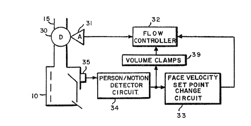
Referring to FTG. Z, a first embodiment of the
present invention is shown as it would be applied to
a conventional fume Y~ood with a damper 30 or similar
air throttling or resistance type flow control
element. This damper controls the flow out of fume
hood In and is actuated by actuator 31. Flow
controller 3~ controls actuator 31 and may consist
' of a ~_on~tant volume controller to maintain a given
volume flow independent of sash position, a two
sta,~e (or mufti-state) volume controller that
~V~ 93/04324 1P~'f/6JS92/07a57
s~ r ,5 ~ c.
N .i 1 t.~
changes the volume of the hood based on the sash
height or open area of the sash, or a variable
volume control system which maintains a constant
f ace velocity based on sash position. U.S. Patent
l3os. 4,741.5'1; 4.58.898; and 4,706,553 describe
various types of variable volume control systems
which could be used for flow controller block 32.
All of these flow controllers work.to maintain a
given setpoint value of face velocity. In the
constant volume systems, this can be interpreted
directly as a setpoint of volume, whereas in the
variable volume systems the fume hood volume will
vary for a given face velocity setpoint. In many
cases, with the variable volume systems, there will
also be a minimum and maximum exhaust volume limit
placed on the fume hood control.
Transducer 35 and person/motion detector circuit
34 work together to detect the presence and movement
of the user/researcher in front of the hood. The
transducer may also detect significant air motion or
turbulence in front of or near the hood. When air
motion or user proximity/movement is detected, it
activates f ace velocity setpoint change circuit ~3.
This circuit acts an flow controller 32 in one of
many possible ways, but generally acts to increase
its f~'~e velocity and/or volume flow setpoint.
Alternatively, it may act to modify the minimum and
maximum exhaust volume limits of the flow controller
through the volume clamps circuit 39.
WU 93/~4324 I'~'111~92/~7Q57
-, ~:a ~
~ 3 '~~
ri
- 16 -
Transducer 85 and detector circuit 34 may be
implemented with a variety of technologies such as
is used in security or intrusion alarm systems. For
example, transducer 35 could be implemented by using
a passive far-infrared (typically 8-14 um) motion
sensor. an active ultrasonic motion sensor, an
active microwave motion sensor, an active
near-infrared (typically 880-940 nm) or visible
light proximity sensor, or a combination thereof.
Based on the type of transducer used, a compatible
detector circuit 34 would be employed.
FIG. 3 illustrates an implementation using a
passive gyro-electric infrared motion sensor and
detector circuit. The pyra~electric detector 41
detects changes in heat patterns caused by the
movement of a person relative to their background
radiation, in a detection zone. The optical system
40, for example a mirror or fresnel lens, focuses
the infrared energy, in for example the 8-1.4 um
spectrum, onto the detector, after a variable gain
stage 42 which controls the sensitivity of
detection, the amplified signal is filtered in
signal processing circuit 43 with a band pass filter
which attenuates unwanted signals and increases the
8~N (signal to noise) ratio of the frequency of
interest;, which is generally in the .3-3 Hz range.
-----
~t~hen the signal is of a desired amplitude,
comparator 44 triggers a timer 45. The timer
Wf.~ 93/O~f324 P~CfJU~92f07057
IFv
- 17 -
changes the state of relay (46), and thus of its
output, f or some preset time period. The output
from relay 46 is applied to control change circuit
33 (FTG.
The timer will restart its timing period if the
comparator triggers a second time within the preset
time period. This preset time period. or turn off ..
delay time, is used to keep the detector on even if
the researcher is still far a few minutes while he
is working in front of the hood, and also to prevent
the nuisance and potential danger of the system
. increasing and decreasing the f ace velocity based on
how still the researcher is while the researcher is
still in front ~f the hood. Alternatively, a
smaller turn off delay could be used if the passive
system were combined with some sort of active
proximity or presence detector.
With the use of variable voltage control 47 the
circuit could detect different zones. For example
the variable voltage output would indicate the
detection of the researcher in the lab relative to a
detection zone an front of the fume hood. The
variable voltage would tell the face velocity
setpoint change block 33 of FTG. 2 to inorea~e the
face yeloci~y a little when the researcher is
present ;in the room and to increase the face
ue1'ocity'even more if the researcher is in front of
the hood.
CVO 93J04324 PCT/US92/a7057
- m -
A complete active system that includes a Doppler
motion detection is shown in FIG. 4. These systems
can be combined ~rith a passive detector and are
typically based on one of ~thre2 technologies:
infrared 800-900 nm, microwaves or ultras~nics. The
active system detects the presence and or movement
of a person. I~Iovement, which indicates where the
researcher is and how fast he is moving, is detected
by the Doppler effect for microwave and
ultrasonics. Presence, which indicates if the
researcher is present at a particular location, is
detected by an infrared beam.
For the circuit of FTG. 4, transmitter 48 sends
a pulse of appropriate frequency into the detection
zone. Depending on the presence of personnel in the
detection zone, the pulse is either returned to the
receiver 49 within a selected clock interval or
not. If the receiver receives the signal,
preamplifier 57. boosts the signal sd that, assuming
the signal is received within the interval of clocl~
50, sample and hold amplifier 5~ can sample the
pu~,ses. with the signals of interest on them. The
pulses are sampled in sync with the transmitted
pulses of clock 50. Doppler/presence detector 53
detects the motion or presence from the sampled
'signal, the presence detector detecting presence of
a signal end the Doppler detector detecting
frequency shift. The signal is filtered and
W~ 93/04324 PC'T/iUS92/07057
_ 19 _
processed in signal processing circuit 54 so that
unwanted signals are attenuated, thus increasing the
S/N ratio for the frequency of interest.
The block diagram of figure 4 illustrates two
potential outputs, one indicating if the researcher
is in the detection zone and the other detecting
where in the zone the researcher is. In the first
case, detecting if the researcher is iii the
detection zone, the output of relay 57 tells the
face velocity setpoint change block 33 of FIG. 2 to
increase the f ace velocity by a present amount. The
later case would change the f~~ce velocity by a
certain percent relative to the distance of the
researcher from the hood.
The presence of the researcher in the detection
zone is indicated by the signal amplitude out of
block 54 increasing until it rises above the
threshold of the comparator 55. The comparator
starts a timer 5~. The timer switches the state of
the relay 57 for some preset time. As for the
circuit of FIG. 3, the timer will reset back to zero
if the comparator triggers a second time within the
timer set period. The relay tells the face velocity
setpoint change block 3~ (FIG. 2) to change the face
velocity.
To indicate the position of the researcher
relativevtb the fume hood, the signal coming out of
block 54 would be converted to a variable voltage by
r-~
WO 93/04324 ~CC°f/U~92/U7U57
~~.:~~~34
- 2~ -
clrcult rJ~s the voltage output telling the face
velocity setpoint change block 33 (~I~. 2) the
distance of the researcher from the fume hood. The
face velocity may then be increased as the
researcher moves closer to the fume hood and
decreased as the researcher moves further from the
fume hood.
The use of both a presence detector and a motion
detector may prove useful to prevent the system from
being adversely affected by people walking past the
hood. If someone walks pa:>t the hood, the system
must quickly activate the active mode. However , if
the person does not stop in front of the hood, but
continues walking, it would be wasteful to leave the
hood in the active mode foy: more than perhaps ZO
seconds. This prevents a g,>erson fram walking around
the room and activating all the hoods
s~.multaneously. The presence detector is desirable
for use in conjunction with the motion detector so
that the active mode is only left on for greater
than 10 seconds if a researcher remains standing in
front of the hood.
F"1G. 5 illustrates another sensing concept to
detect a person walking up to and, standing in front
of the hood. This involves a floor mat type switch
36 which is activated by standing on a special mat
placee3 5.n front of the hood. These devices are of
the general type used to open doors, although
W() 9~104~24 Pt.'f/1JS92/07057
- 21 -
generally modified in appearance and construction to
fit in better for a laboratory application. For
example a capacitive plate sensor or inductive plate
sensor which would operate by stepping on a sheet of
metal either on top of or embedded into the floor
would provide a neater installation for this
application which would be less affected by spilled
chemicals, There are also many similar sensors such
as piezoelectric or FSR (Force Sensing Resistor)
which are very flat and can for example be laminated
into. corrosion resistant plastic. Detectors of this
type typically work on press>ure or on the capacitive
or conductive affects of the human body. Except for
the change in detector, fhe system of FIG. S has the
same components and operates> in the same way as the
system of FIG. 2.
then passive or active detectors such as those
shown in Figs. 3 or 4 are used. the optics of the
system will need to be adjusted to sense the proper
area in front of the hood. Some field adjustability
is desirable based on the different sizes of hoods
and different lab casework layouts in which the
hoods are applied. FIG. 6A shows a typical detector
zone 50 for a detector 35 that is mounted on a hood
l0 as shown in FIG. 6E. In some cases, two or more
detecto_~s, may need to be used ar special optics may
be4~required that can specifically shape the
detecrtion field of a single detector. For example,
W~ 93/04324 P~.'ff ~S92f0705 7
. s ~, 3
~ri' s.. ..~~. ;fir .~ ~ ~~
it may prove useful to observe the hood area from a
height of 3' ar 4' on up to ignore chairs, tables,
equipment and other fixed or movable~objects. When,
for instance, infrared detectors are used, special
fresnel type lenses or specially shaped mirrors may
be used. The size of the zone 50 would vary with
application. For example, the zone might extend 1.°
to 4'from the front of the hood and beyond each side
of the hood by from 0 to ~'.
ether means to implement sensor 35 and detector
circuit ~4 would be through creating a light curtain
or projecting a light beam around the desired
detection zone, 50 of FTG. 6A. When an ope~rabor
crosses and momentarily breaks the light beam, the
detector circuit signals the presence of the
operator. The circuit of FTG. 4 could be used to
implement this type of detector circuit.
Tn addition to sensing the presence or motion of
a user near the hood, there are, as was mentioned
earlier, potentially other factors which might
dictate the need for a higher f ace velocity, for
ex~~ple, the presence of an: air velocity greater
than 30 to 50 FPM such as from a nearby supply air
diffuser. Additionally, the presence of apparatus
in the first 6" or so of the hood back from the
from Y~ the sash can also decrease hood
containment, necessitating the need far a higher
face velocity.
w~ ~3iod~x~ ~~°ous9xi~~os~
- 23 -
There are many finds and types of air velocity
sensors that could be used to detect air motion,
either in front of or at the corners or sides of the
fume hood. tTnfortunately, many of these tend to be
point sensors such as hot wire or thermistor--type
thermal aneometers. ~ better system~wouid sense the
presence of low air velocity over a wider area. one
such approach would use long streamers; 51 (FIG. 6~)
the length of each such streamer being roughly equal
to the height of the sash openings. The streamers
5l would be placed at the front corners or edges of
the hood where the hood is most affected by air
currents. These streamers would be made of some
13~h~'m~terial easily maved by wand or other air
curi~ez~ts striking the streamer. The motion of the
streamers could then be detected by the motion
detectors that were described earlier.
~lterna~ively; the motion could be detected directlx
by ~ suitable motion detector 52 to which each
streamer 51 is attached. As each streamer moves)
its motion is transmitted to the corresponding
detector 52, which senses the motion by for example
movang the contact point on a variable resistor or
b,~ sensing the variation in pressure, weight or
twisting forge applied to a sensitive force
measuring, device such as piezoelectric or strain
_ ( -;
:gauge transducer. '
W~ 9~/0~1~24 a ~ .~ ~ ~ ~ t~ tp~ 11~~US921~D7~57
An even simpler approach is to use the
pyro-electric or heat sensor mentioned earlier.
These devices can be made,sensitive to the motion of
air that is at a different temperature than the
background. For example, the conditioned supply air
.coming out of a diffuser near a hood is typically
55~f'. versus the background room temperature of
'70°F. depending on the turbulence of the airflow
near the hood, this air motion would be detected by
the pyro-electric sensor.
As mentioned earlier, one other factor affecting
hood capture is the presence of apparatus in the
first 6" of the hood work surf ace. This region 55
is shown in FIG. 6A. To sense this condition, a
simple active or proximity sensor could be used to
send a light or other type of beam from one side to
the other side of the inside of the hood. Anything
placed in the gone traversed by the beam would
signal the system to increase the face ~relocity.
one implementation shown in FIG. 6A has an active
transmitter and receiver unit 56. This unit bounces
a light, ultrasonic, microwave or other appropriate
wavelength beam 58 off reflector 57 and back to the
transmitter/receiver unit 56. The circuit of ~'TG. 4
could again be used to implement the sensor and
detectar~.~ircuits. Pressure sensitive '°floor mat"
type switches, og equivalent pressure sensing
material strips, could also be used to detect the
presence of apparatus in "buffer" gone 55.
rwo ~~io~3x~ ~~rus~x~o7os°~
IJ
- 25 -
mother method to determine if there are
influences that are disturbing hood containment is
to actually measure the containment of the hood in
some way such as by releasing a harmless fluid, such
as a tracer gas or vapor in the hood and measuring
outside the hood to see if any is escaping. This
measurement of the hood's containment could be used
to help vary the f ace velocity to the optimum point
or to provide a two step operation.
As mentioned earlier, one approach to detect air
motion in, around or near the hood is to use an air
velocity sensor that measures the air velocity near
the hood to directly look fear high velocities that
could affect containment. alternatively, an air
velocity sensor either in the sidewall or someplace
an front of the hood could be used to detect
disturbances caused by a user standing in front of
the hood or by air turbulence near the hood. The
former could be sensed, for example, by observing an
increase in the air velocity through the sensor when
in fact no change in the actual face velocity (which
would also be detected or probably computed by using
exhaust volume and sash area measurements)
occurred. In order to sense air turbulence, the
variations or "noise" in the air velocity signal
could b~,pbserved. A very noisy signal that was
changiixg a lot would indicate the presence of air
turbulence near the hood. In order not to be
VVO 93/84324 ~.~ ~~ ~. ~ ~ ~ P~"f/Y1S92/07057
- 26 -
confused with changes in velocity caused by movement
of the sash, the sash position or the effective area
of the sash could be monitored if it was desired to
separate out any air velocity changes caused by the
movement of a sash.
Alternatively the actual exhaust volume of the
hood could be measured or metered by appropriate
means and this value could be divided by the sash
position to generate a calculated face velocity.
Variations betweezx this term and the sidewall f ace
velocity could be then compared, particularly on a
transient basis, in order to detect disturbance
causing c~nditions around or inside the hood.
The last sensor that might be utilized to vary
or change f ace velocity is a sash, movement sensor.
Movement of the sash or sashes creates turbulence;
therefore, an increase in face velocity during and
after the movement of the sash might help to
increase the hood's cantainment of fumes during such
an operation. The movement of the sash can be
easily sensed by the use of a sash sensor such as
thoVe described in U.S. Patents 4,528,898 and
~, 706, 553 cahere a spring--wound, multiturn pot
assembllr is used to measure sash height . A
differentiator circuit such as that shown in FIG. 7
could b_e_~ased to detect even a small movement of the
sash.v Iii this figure, sash sensor 62 produces a
variable voltage signal that is differentiated by op
W~ 93/04324 P(.'T/~J~92/07~57
_ 27 _
amp circuit 60. Comparator 61 compares the
differentiated signal to a reference to generate a
two-state output that could be used to switch a
relay when the sash moves.
As mentioned earlier, the system utilized could
involve many of the different sensors described
above in combination. Also, the outputs of the
different sensors might be utilized.as variable
outputs or as two state or relay outputs in order to
detect the magnitude of the disturbance or closeness
of a person to the hood. This variable output might
be used to create a variable face velocity with a
magnitude depenr~ent on the magnitude of the
disturbance.
~3lock 33 of FIG. 2 is the circuit which accepts
the relay closure or signal fram the disturbance
detector or detectors 34 in order to modify the face
velocity or volume command of the flow controller
~l~ere are several ways in which the face
vezocxty or volume could be changed in order to
incxease containment when a disturbance occurs.
FTG. ~ is a diagram indicating one way that dolume
could be changed. In this example, the hood is
operated with a standby face velocity of 70 FPM
which is shown by lines 131 and 105 which intersect
at the~c~i.nt 149 of minimum flow, which point in
. this dxample occurs at 20°s of open area. When a
disturbance occurs, the face velocity is increased
WO 93/0432~d P~T/U~92/07057
_ 2~ _
producing a flow-to-sash-position curve outlined in
FIG. 8 by lines 130 and 104. Under some situations,
it may be desirable to maintain the same minimum
flow for both standby and active 4disturbance)
modes. This is shown in FIG. 8 by the curve
including lines 130, 134 and 105. In this example
the minimum flow occurs at 28.6 of the full open
sash at point 135. For operations Tong lines 130,,
131 and 134, f ace velocity will iincrease as sash
opening decreases to maintain the desired constant
flow volume.
Sim~.larly, it sometimes is advantageous to have
a maximum limit for both si.andby and active modes.
FIG. 9 shows this with an ~xaa~n~le where the stanc'fby
mode uses 70 FPP2 within bofih minimum and maximum
limits. The standby mode is ind~.cated by lines 132,
107 and 120. Foiz~ts 110 azld 111 indicate the
minimum and maximum limit intercepts, respectively.
The s.ctive mode at 100 FPM is indicated by lines
132, 106, and 120. The intercept points are 108 and
10~ for minimum and maximum limits, respectively.
different maximum limits may also be employed as
shown ~~r the 100 FPM curve 132, 106, 137 and 136
where point 112 is the maximum intercept point.
,gain, for operators along lfines 120 or 136, face
veloci~,yr will decrease as sash opening is increased
to maintain constant volume flow.
6~V0 93/04324 1PC°I'/~IS92/07057
-- 2r~ -
Another way of operating the system is to have
the face velocity constant at some value such as 100
FPM, but a maximum clamp is engaged when a
disturbance is detected. FIG. 10 illustrates this
where lines 133, 113 and 121 would indicate a
standby mode with a maximum clamp level.of, for
example. 50%. Under the active mode, the clamp i.s
rained 'to 70% as shown by lines 133_, 113. 114 and
123. Alternatively the maximum clamp may be
eliminated altogether in t;he active mode ~s
illustrated by extending line 114 to point 117 where
100 open occurs at 100°s flow.
Tn other cases, it may be useful to add or
subtract an offset to the lhood's flow versus changes
in the face velocity. FTG. l3 shows an example of
this where lines 148 and 140 indicate a standby made
and lines 1~8 and 141 indicate the active mode,
offset 147 being the difference. A maximum clamp
may also be added in the active mode as shown by
line 124 with an intercept point of 145.
It is also passable to operate a fume hood
system at a substantially constant volume through
most positions of the sashes, with a trip switch or
other element being utilized to reduce the volume
for sash openings below a selected threshold. Thin
resul~s,,in a stepped, varying face velocity curve
with changes zn sash position, the step occurring at
the threshold position. This stepped face velocity
WfJ 93/04324 P~ f>US92/fl7057
.s r i ~ ; s'4
i ' 2.~ ~ z~ ~~
~n~~ A. ..~.
30 -
curve may have an offset superimposed thereon in
accordance with the teachings of this invention
based on detected Containment affecting conditions.
Another variatian would be to have multiple face
velocity.levels or a variable f ace velocity based on
conditions near the hood. Alternatively, a single
face velocity could be used with multiple maximum
clamps or again a variable maximum d amp based on
hood conditions .or disturbances. FTC. 10 shows a
situation where th~~e different maximum clamps are
used. These might correspond, for example; to a
staaadby mode where no one is near the hood, an
active mode where someone is standimg qsaietly near
the hood, and a turbulent made where rapid motion is
detected near the hood. The maximum clamps
indicated by lines 121, 123, and 122 would
correspond, respectively, to these conditions.
A typical schematic block diagram which could
implement block 33 of FIG. 2 for a single or
multiple relay contact closure is shown in FIG. 12.
In this figure, the active or highest face velocity
or flow volume setpoint is provided and adjusted by
a trimpot 70 which is buffered by op amp 71 and is
then attenuated by the faxed andJor variable
resistor string 72, 73. 74, and 77. ~,elays 75 and
76 are_~~e output relay or relays of the disturbance
de;tector~ circuitry of block 34. If only two states
of ~p~rataon are desired, then only relay 75 and
W~ 93/04324 Pd.'ft'/L1S92/~7~57
3d
~...~~~u~.;.'
3 ~ i
fixed or variable resistor ~3 is used. For three
states of operation, relay 76 and resister 74 can be
added as shown. The output of this attenuation
circuit can then be buffered as shown in op amp 78.
Additional relays and resistors could be added for
even more states if desired.
Tf a true variable control is desired, then the
output of op amp '~l could be multiplied by using an
analog or digital signal multiplier circuit with a
variable output signal from the disturbance detector
block 34. The resultant output signal from this
multiplier or the output from op amp 78 of FTG. 12
is then used as the face velocity setpoint or volume
setpoint value for flow controller 32 of FIG. 2.
As was mentioned ~arlierp many different vol~ne
or f ace velocity controllers may be used for block
32. Additionally, depending on the control approach
desired, an additional circui block may be needed
to provide maximum and/or minimum volume clamps.
This block is shown in FIG. 2 as block 39. This
block may be implemented with fixed volume clamps or
variable clamps that are controlled by the
disturbance detector. The circuit of FTG. 12 can be
used to implement these variable maximum or minimum
damp setpoint circuits. If both clamps are desired
,, ; to be variable, then two of these circuits would be
needed :f
wo 93roa~2a
fCT/US92/07057
32
FIG. 13 shows how these c lamps could be
implemented in conjunction with block 32. The
minimum and maximum volume clamp signals 86 and 87
respectively from block 39 of FIG. 2, being either
fixed or variable signals, are then used as input
signals to the actual volume clamp circuits in block
32. The actual minimum clamp circuit is implemented
with op amp 82, its associated diode. and resistor
84. The actual maximum clamp circuit as implemented
with op amp 83. its associated diode and resistor
85. These clamps work on a linear volume command
output on line 88 from velocity or volume control
block 80. The linear clamped signal is thus used to
drive block 81 which in turn controls the volume
moving through a damper, or air flow contral valve.
If a variable speed drive or inverter is used to
control flow instead of a damper, FIG. 14 shows how
the system can be implemented. Operation is the
same as for FIG. 2, except damper 3~ and actuator 31
are replaced by block 14 which consists of a blower
and blower speed controller. Far the blower system,
block 81 (FIG. 13) would be used to control the
:blower speed.
In both FIGS. 2 and 14, optional sash sensor,
velocity sensors or volume sensors can be used in
con~uncti9n with the flow controller block 32 to
provide proper control of face velocity or flow.
U.~. patent Nos. 4,528,898 and 4,706,553 illustrate
wc~ ~3io4~z~a pc.-t'i~s~z~o~os~
.~.~.i~J~~~
33
some typical applications and implementations of
block 3z using these sensors.
While the invention has been shown and described
above with reference to various embodiments, and
specifio implementations have been shown and
suggested for var~.ou~ elements of the system, it is
apparent that the various sensor and control
circuits shown are merely illustrat~.~re and that
other devices and techniques might be utilized an
particular applications. Thusa while the invention
has been particularly shown and described above for
the preferred embodiments. the foregoing other
changes in form or detail may be made therein by one
skilled in the art without departing from the sprit
and scape of the invention.
6a;~.x zs ~z~AZt~n z~