Note: Descriptions are shown in the official language in which they were submitted.
` ` 2116429
I NJECTI N& APPARATUS
This invention relates to injecting apparatus for injecting a
fluid under pressure, e.g. fuel injecting apparatus for internal
combustion engines, apparatus for injectin~ liquids, e.g. a catalyst
into chemical reaction vessels under pressure, and other apparatus
for injecting a dose of fluid.
Although the present invention is applicable to any situation
where a measured dose of fluid is to be injected under pressure~ it
will be convenient to describe ~he invention with particular
10 reference to injecting fuel into an internal combustion engine,
Fuel injectors used in internal combus~ion engines, lncluding
both spark ignition and compression i~nition ~or diesel) en~ines
generally utilise an external pump for supplying the fuel under
sufficient pressure to be injected into the engine cylinder. The
15 timing of the injection point in the engine operating cycle is
determined by externally controlling the operation of an injector
valve by mechanical means. One disadvantage of providin~ external
pumpin8 and control is the need for the provision and servicing of
such external systems.
A general problem with injectors~ particularly ones supplied
from an external pump, is lack of responsiveness to any faulty
condition in the associated cylinder. For example, if a piston ring
is broken, known injectors will continue to inject fuel char~es into
the cylinder. Thus fuel will be exhausted from the engine leading to
2~ air pollution by e~hausted unburnt fuel.
It has been proposed in the past to utilise the build up of
pressure within the cylinder of an internal combustion engine during
the compression stroke to provide the motive force to compress fuel
within the injector body. For example, there has been proposed a
30 ~uel injecto~ which has a body, and a piston which is movable within
the body under the action of cylinder pressure. The movement of the
piston in the injector body causes an increase in pressure of a fuel
charge introduced into the body to a point where the pressure enables
a non-re~urn valve associated with the injector nozzle to open and
35 allow the fuel to be in~ected under pressure into the engine
.. . ... ... . .. . .. . . .. ..
2116429
cylinder. Problems with this device include difficulty and
uncertainty in closing of the valve leading to fuel continuing to
dribble from the injec~or after the desired cut off pointt and also a
~ener~l lack of control over the operation of the injector.
US patent No. 2,516,690 in the name of French shows a fuel
injector which utilises the associa~ed en~ine cylinder pressure to
develop the pressure to iniect the fuel. The French apparatus has a
simple spring biased non-return valve at the injection nozzle so that
the opening and closing of the injection nozzle is solely con~rolled
10 by pressure dif~erential and spring force. Some control of pressure
developed is provided by a non-return valve in an outlet from the
pumping chamber and an adjustable flow restrictor downstream of the
non-return valve. The French apparatus has very limited ability to
enable control of the injector operation including timin~, injection
15 pressure, volume of fluid injected, and degree of positiveness in
action.
US patent 4,394,856 in the name of Smith also shows an injector
using engine cylinder pressure to develop the injectin~ pressure.
The Smith apparatus uses a non-return valve as the injection valve.
20 A solenoid operated non-return valve is provided in the outlet from
the pumpin~ chamber and an adjustable flow restrictor is provided in
the outlet line downstream of the non-return valve to enable
adjustment of the possible rate of flow when the solenoid non-return
valve is opened, In a similar manner to the French US patent, the
25 Smith injector has very limited ability to enable control of the
injector operation includin~ timing, injection pressure, volume of
fluid injected, and degree of positiveness in action.
US patent No. 4,427,151 in the name of Trenne shows a similar
injector to the Smith injector except that there is provision for
30 adjustin~ clearance between the outlet valve member controlled by
the solenoid and its associated seat so that that adjustment enables
some control of the flow rate for fuel flowin~ out of the control
ch~mber. As with the French and Smith specifications, the Trenne
injector has limited degrees of control and limited positiveness in
35 operation7 particularly the non~return injector valve.
According to the present invention there is prpvided an
in~ec~ing apparatus for injecting a fluid under pressure, the
211Sll29
injec~ing apparatus including: a body, piston means movable in the
body under the action of externally applied fluid pressure, the
piston means being operable to compress in a high pressure chamber,
fluid to be injected the piston means being movable against the
action of fluid pressure in a low pressure chamber whereby the
movement of the piston means is selectively controllable by
controllin~ ~he fluid pressure in the low pressure chamber, and an
injection valve and an associated injection orifice in fluid
communication with the high pressure chamber whereby high pressure
1~ fluid from the high pressure chamber can be injected through the
injection orifice upon opening of the injection valve.
Preferably the injection valve which controls injection of high
pressure fluid through the orifice is selectively controllable in its
operation. The injection valve may include a valve member movable
15 against the action of fluid pressure in a control chamber, the fluid
pressure in the control chamber being selectively controllable to
control operation oE the injection valve. The control chamber is
preferably in fluid communication with the low pressure chamber
wh~reby an increase in ~luid pressure in the low pressure chamber to
20 resist movement of the piston means also increases the fluid pressure
in the control chamber resistin~ opening of the injection valve.
In the preferred embodiment the high pressure chamber
communicates with the injection orifice through a delivery chamber,
the hi~h pressure fluid from the high pressure chamber being supplied
~5 to the delivery chamber through a non-return delivery valve, the
non-return delivery valve being operable to close the delivery
chamber and maintain in the delivery chamber a charge of fluid stored
under pressure. Preferably the non-return delivery valve has a valve
memher having a ~irst sta~e of movement in which it moves to stop
30 communi~ation from the pressure chamber to the delivery chamber and a
second stage of movement in which the valve member after having
completed its first stage of movement allows limited pressure relief
in the delivery chamber so as to thereby reduce the fluid pressure
upstream of the injection valve.
The piston means is preferably movable under the action of the
externally applied fluid pressure a~ainst the action of a main
spring, the force applied by the main spring at least in part
2 9
determining the externally applied fluid pressure necessary to
initiate movement of the piston means, the injectin~ apparatus
further including a delivery spring aDainst the action of which the
injection valve moves to allow fluid injection through the orifice,
the strength of the delivery sprin~ determinin~ at least in part the
pressure of fluid in the hi~h pressure chamber necessary to open the
injection valve to allow fluid injection throu~h injection orifice.
Preferably there is provided a bleed path for hi~h pressure
fluid to bleed from the high pressure chamber upon movement of the
10 piston means by a predetermined maximum extent, the opening of the
bleed path as a result of said predetermined maximum movement
occurrin~ relieving fluid pressure in the high pressure chamber to an
extent sufficient to stop injection of fluid through the injection
valve.
1~ The present invention also provides an injectinV system
comprisin~ an injecting apparatus according to the invention, a fluid
pressure relief path throu~h which fluid pressure in ~he low pressure
chamber can be controllably relieved to permit and control movement
of the piston means, and an associated fluid pressure governor means,
20 the ~overnor means being selectively controllable to control the
fluid pressure in the low pressure chamber by selectively preventing
or progressively limiting relief of pressure from the low pressure
chamber through the fluid pressure relief path in response to
movement of the piston means.In this iniecting system, the ~overnor
25 means may include a flow restriction means in the fluid pressure
relief path to selectively control the cross sectional area of the
fluid pressure relief path, the flow restriction means havin~ an
associated drive means so as to drive the flow restriction means to
vary the cross sectional area of the relief path, the governor means
30 further inclu~in~ a back pressure valve located in the fluid pressure
reIief path, downstream of the flow restriction means, the back
pressure valve being operative to maintain a predetermined minimum
back pressure in the fluid pressure relief path by only opening when
the predetermined minimum bark pressure is exceeded.
The fluid pressure relief path preferably includes a pressure
compensating means which includes a restriction and varying means for
varying the size of the restriction in response to changes in fluid
2116~29
pressure downstream thereof, the varyin~ means being operative to
reduce the area of the res~riction to maintain a predetermined
pressure downstream of ~he pressure compensatin~ means. The pressure
compensating means may comprise a chamber which co~municates with the
low pressure chamber, the pressure compensating means further
including a shuttle valve responsive to the pressure differential
between the fluid pressure in that chamber and a point further
downstream in the fluid pressure relief path and being operative in
response to an increase in the pressure differential to reduce the
10 area of the restriction and thereby retard pressure relief from the
chamber to the point further downstream.
The injecting system may further include a controllable damper
means in communication with the fluid pressure relief path, the
damper means including a movable damper member responsive to a
15 pressure increase in the fluid pressure relief path to yield so as to
thereby relieve pressure in the fluid pressure relief path, the
damper means further including an adjustable limiting means
associated with the movab~e damper member to controllably limit the
extent of yielding movement, the limiting means chereby effectively
20 determining the pressure relief provided by the damper means. The
movable damper member may comprise a resilient damper disc which
defines one wall of a chamber which is in communication with the
fluid pressure relief path7 the limiting means comprising a limiting
stop which is adjustable so as to be contacted by the damper disc.
The iniecting system in another embodiment may be characterised
in that the fluid pressure relief path includes a high speed solenoid
valve operative to open and close the fluid pressure relie~ path in
response to actuation signals, the governor means being located
downstream of~ the solenoid valve and being nperative to adjustably
,_~
30 limit in continuous increments the flow of fluid through the fluid
pressure relief path.
Possible and preferred features of the present invention will
now be described with particular reference to the accompanying
drawings. However it is to be understood that the features
35 illustrated in and described with reference to the drawings are not
tn be construed as limiting on the scope of the invention. In the
drawings:
2116~29
Fi~. l shows a cross sectional view -throu~h an injector
according to the present invention,
Fi~. 2 shows a cross sectional view through one possible
arrangement of a governor or accelerator for use in controlling
operation of the injector,
Figo 3 is a cross sectional view through an alternative
construction of injec~or accordin~ ~o the present invention,
Fig~ 4 is a cross sectional view throu&h thP rear portion of a
further possible construction of injector showing various means for
lO enabling control of the injector operation,
Fig. 5 is a plan view o~ the detailed section marked "A" in
Fig. 4, and
Fig. 6 is a sectional view alon~ ~he line VI - VI in Fig. 4.
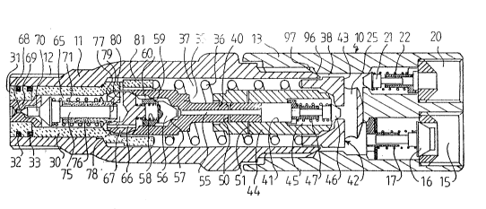
Referring ~o Fig. l, the injector includes a body lO which
lS comprises a front body part 11 which can for example have a threaded
end 12 for engagement in a threaded port associated with an engine,
and a rear body part 13. An inlet l~ is provided in the body 10, the
inlet 15 havin~ a non-return valve 16 operated by spring 17. In use,
fuel is supplied or induced under low pressure in~o the inlet 15
20 sufficient to overcome the action of spring 17. The strength of
spring 17 is not critical. The fuel pressure can be relatively low
so that high pressure fuel lines are not required.
An outlet 20 has an associated non-return valve 21 acting by
means of spring 22, the strength of which is not critical. With this
25 arrangemen~, fuel can continuously be pumped or induced under low
pressure into inlet 15, through passage 25 and out through outlet
20. This continuous fuel flow can provide coolin~ although
supplementary coolin~ could be provided.
: :,
The injector includes a low pressure piston 30 slidable in the
30 front body--,rl when engine cylinder pressure acts on the front face
31. Compression ring 32 and oil scraper ring 33 are provided for
con~entional purposes. Screwed to ~he low pressure piston 30 is a l ~- -
high pressure piston 35. ~le piston assembly 30, 3~ moves within the
body 10 against the action of main sprin~ 36. The force applied by -~5 main spring 36 determines, in par~, whether the piston assembly 30,
will move under t~e ~ction of cylinder pressure on face 31. Also,
the main spring 36 is located in a low pressure chamber 37 which is
2116~2Y
in fluid communication through space 38 with the passage 25 and
throu~h valve 21 with the outlet 20 so that the fluid pressure in low
pressure chamber 37 resisting movement of the piston assembly 30, 35
can be relatively low, subject to control to be described later.
A possible variation of the preferred construction illustrated
and described is the replacement of the main spring 36 with a
pneumatic or other biasing means.
The hi~h pressure piston 35 has an extension 40 of relatively
small cross sectional area which travels within a bore 41 provided
10 within a high pressure body 42. The hi~h pressure body 42 comprises
a base section 43 and a high pressure barrel 44 in which the
extension 40 travels. The base section 43 and high pressure barrel
44 are secured together and define a hi~h pressure chamber 45 in
which fuel is compressed to high pressure by the extension 40 of the
15 high pressure piston 35. Non-return valve 46 operated by a spring 47
allows fuel to enter the high pressure chamber 45 from the passage ~5
upon retraction of the high pressure piston extension 40 in the bore
41. The stren~th of spring 47 is not critical.
In the extension 40 there is provided a bleed bore 50 and
20 extending throu~h the high pressure barrel 44 is a bleed bore 51
which opens into the low pressure chamber 37. If the stroke of -the
piston assembly 30, 3~ is sufficient for the bleed bore 50 to align
with the -bleed bore 51, the fuel within the high pressure chamber 45
is immediately placed in communication with the low pressure chamber
25 37 and the fuel pressure in high pressure chamber 45 will immediately
drop so that there will be insufficient pressure for fuel injectivn
to continue as will be described later. Thus the longitudinal
separation between the bleed bore 50 and the bleed bore 51
effectively defines the maximum fuel char&e that can be injected
30 during on~-;~troke of the piston assembly 30, 35 and this, in turn7
effecti~ely limits the speed of running of the associated engine to a
predetermined maximum determined by the maximum fuel charge.
Running longitudinally through the extension 40 of the high
pressure piston 35 is a fuel passa~e 55 alon~ which pressurised fuel
35 from the high pressure chamber 45 travels as the piston assembly 30,
moves under the action of the cylinder pressure. The fuel passes
a non-return delivery valve 56 which is shown resting against
2116~29 ~ ~
~ .
shoulder 57 under the action of spring 58. In operation, high
pressure fuel moves valve 56 away from shoulder 57 against the action
of sprin~ 58. Fuel flows past the valve ~6 only when it has moved
sufficiently for the shoulder 59 of the valve to move past the end of
passage 60 formed on the inside surface of the high pressure piston
35. With this arrangement, when delivery valve 56 is closing, ~uel
flow past the valve 56 is s~opped when thc shoulder 5~ reaches ~he
end of the passa~e 60, after which the valve 56 continues to move by
a further limited extent until the valve 56 reaches shoulder 57.
10 This continued movement of valve 56 after the valve has closed off
fuel flow relieves pressure on the downs~ream side of the valve ~6
for a purpose which will be described later. -
The low pressure piston 30 has a delivery chamber 65 into whichhigh pressure fuel is introduced through bore 66 provided in the
15 spacer 670 At forward end of the delivery chamber 65 is a delivery
orifice 68 provided in an insert 69. The orifice 68 is shown closed
by needle type delivery valve 70 which seats against the insert 69
under the action of delivery spring 71. When the pressure of fuel in
the delivery chamber 65 is sufficiently great, the needle valve 70
20 moves against the action of delivery sprin~ 71 and opens the orifice
68 and fuel is injected through the orifice 68 into the associated
en~ine cylinder. The commencement of injection through orifice 68
causes an immediate drop in fuel pressure in delivery chamber 65 and
the needle valve 70 will tend to close the orifice 68 again. This,
25 in turn, will allow pressure in delivery chamber 65 to rise and again
open needle valve 70. This process continues so that the needle
valve 70 opens and closes the orifice 68 at high speedO This action
is known as "buzzing" of the delivery needle valve 70 and causes the
fuel to be injected through orifice 68 in waves and this is believed
30 to improve~ l combustion efficiency.
The needle valve 70 has a shank 75 which moves within a guide
76~ The end 77 of the shank 75 remote from the delivery orifice 68
closes a con~rol chamber 78. Control chamber 78 communicates through
(aligned) bores 79, 80 provided in the spacer 67 and low pressure
35 piston 30 respectively and through the space 81 around the outside of
the low pressure piston 30 with the low pressure chamber 37. Thus
the control chamber 78 is normally in communication with low pressure
. ~ .
,, . , . .... . , . .,. , . . .. .. , , . . I , . , . . . ~ . . . . . . . . . . . .
211(i~29
fuel allowin~ the needle valve 70 and shank 75 to move away from the
insert 69 to open the orifice 68 under the pressure of fuel in the
delivery chamber 65.
Referring to Fig. 2, there is shown an accelerator or governor
means which enables control of the flow of fuel on the downstream
side of the injector. In particular, in use, the governor means
shown in Fig. 2 comprises a body 85 having a bore 86 which is in
communication with the outle~ 20 of the injector. The downstream end
of the bore 86 is provided with a chamfered seat 87. Longitudinally
lQ selectively movable within the bore 86 is a governor 90 which has a
complementary chamfered shoulder 91 which can close against seat 87
to completely close bore 86. The ~overnor 90 has a shank 92 which
extends into the bore 86 and is a close fit within the bore. The
shank 92 has a ~roove 93 which tapers from the shoulder 91 to the
15 upstream end g4 of the shank 92~ The fuel can flow into the bore 86
along the groove 93 and between the shoulder 91 and seat 87 when the
governor 90 is retracted longitudinally in the direction of arrow A.
If the governor 90 is retracted only slightly from the seat 87, flow
along the groove 93 is significantly restricted since the fuel must
~0 flow through the shallowest end of the groove 93 where the seat 87
meets the bore 86 at point 95. If the governor 90 is retracted
further in the direction of arrow A, greater flow past point 95 is
possible because of the deepening of the groove 93 towards the end
94. Thus the selective retraction and insertion of the governor 90
25 from and into ~he bore 86 enables control of the pressure in low
pressure chamber 37 of the injector, which in turn, can control the
stroke of the piston assembly 30, 35. If the ~overnor 90 is moved to
contact the shoulder 91 against the seat 87, the fuel flow through
outlet 20 of the injector i5 prevented and this will hydraulically
30 lock the ~ ston assembly 30, 35 against movement by blocking the
pressure relief path for fuel from low pressure chamber 37.
The movement of the governor 90 in Fi~. 2 can be achieved by
any suitable means such as a mechanical adjustment of the position of
governor 90. Alternatively the go~ernor 90 could be moved by a DC
35 electric motor or linear motor enabling elec~ronic control of the
fuel injection. In this way, it is possible to infinitely vary the
fuel injection by controlling governor 90 in a continuous manner,
21164~9 ~
. ,:
thereby controlling continuously the low pressure side of the
injector which in turn enables control of the point in an operating
cycle at which movement of the piston assembly 30, 35 is allowed to
commence. In general terms~ the hydraulic control of the low
pressure side of the piston assembly 30, 35 of the injector enables
precise control of the point of commencemen~ of the stroke of the
piston assembly 30, 35 which controls the amount of fuel injected, up
to a maximum charge determined by the spacin~ of the bleed bore 50
and 51.
In operation of the injector in an internal combustion engine~
the increasing pressure on the front face 31 of the low pressure
piston 30 during the compression state of the en~ine will tend to
move the piston assembly 30, 35 agains~ the action of both the main
spring 36 and the fluid pressure in chamber 37. I the pressure
15 re7ief from the low pressure chamber 37 through outlet 20 is
.: ~
permitted, the piston assembly 30, 35 retracts to compress fuel in
high pressure chamber 45. The fuel flows through fuel passa~e 55,
. ~ ,....
past delivery valve 56 and into deli~ery chamber 65. The pressure in
chamber 65 causes the needle valve 7Q to open a~ainst the action of
20 both delivery spring 71 and the pressure in low pressure chamber 37
: which, in turn, is in communication with control chamber 78 so that
fuel injection through orifice 68 commences.
Initially, fuel will be injected in relatively large droplets
since the pressure in the engine cylinder is sti.ll relatively low,
25 ~owever, in the case of a compression ignition engine, immediately
ignition of the fuel in the cylinder occurs, there is a rapid
increase in cylinder pressure which acts on face 31 of the piston
30. This pressure jump immediately causes a multiplication of the
fuel injection pressure so that the fuel being injected through
30 orifice 68~ a ~reatly increased pressure will emerge in mu~h
smaller droplets which impro~es the combustion efficiency, The
initial injection pressure jump may be from 4000 psi to 25000 psi.
The ra~io of injection pressure to input pressure may be between 6
and 12~
It is possible ~o control the proportion of the total fuel
char~e which is injected at the initial relatively low pressure by
adjustment of the stren~ths of the main sprin~ 36 and the delivery
2 116 l 29
sprin~ 71. For example, increasing the strength of the main spring
36 retards the point of movement of the piston assembly 30, 35 thus
delaying the commencement of injection and reducing the proportion of
the fuel which is injected during the initial low pressure injection
stage prior to ignition. By adjustment of these spring forces, it is
possible to affect the efficiency of combustion and hence control
emissions, e.g. for different cylinder sizes. The ratio of the high
and low pressures of injection is also controllable.
The maximum fuel charge is determined by the spacing of the
lO bleed bores 50, 51 which effectively also provides a ~aximum engine
speed limiter. In particular~ when the bleed bores 50 and 51 align,
the fuel pressure in the high pressure chamber 45 is immediately
relieved through the bleed bores 50, 51 and this pressure drop is
immediately conveyed to the delivery chamber 65 so that the needle
15 valve 70 immediately closes.
The external control of the pressure relief through the outlet
of the injector, e.~, by means of the governor means shown in Fig.
2, not only controls the point of opening movement of the piston
assembly 30, 35 but also cuntrols the low pressure side in chamber 37
20 during an injection operation. If the pressure relief through outlet
is retarded, the movement of piston assembly 30, 35 is limited by
the relief of pressure in the low pressure chamber 37 and also the
opening movement of the needle valve 70 is resisted by the retarded
relief of pressure in control chamber 78 actin~ a~ainst face 77 of
25 the shank 75 of the needle valve 70. Thus low pressure side
hydraulic lock up controls termination of the fuel injection
operation, ~lternatively, the termination of the injection operation
occurs when the maximum fuel charge is injected and the bleed bores
50, 51 align and cause an immediate high pressure side pressure
30 drop, In_ ~ither case, the delivery needle valve 70 closes the
orifice 68. The delivery valve 56 also will immediately move towards
its closed position under the action of spring 58 so that the
shoulder 59 reaches the end of passage 60 thus closing off
communication between the high pressure chamber 45 and the delivery
35 chamber 65. Because the delivery valve 56 continues to move beyond
the point at which shoulder 59 reaches the end of passa~e 60, the
fluid pressure in delivery chamber 65 can continue to be relieved
2116 Z29
preventing opening of needle valve 70 until high pressure is a~ain
built up in delivery chamber 65. These combined actions of hydraulic
lock up of the low pressure side or high pressure side pressure
relief, to~ether with the two stage movement of the delivery valve 56
ensure immediate and positive termination of the fuel injection.
The injector shown in Fig. 3 is in most respects the same as
the injector shown in Fig. 1 and the same reference numerals are used
for correspondin~ parts.
Different eatures in Fig. 3 include the modified needle valve
10 70 which, instead of a conical tip, includes a blunt nose portion 70a
which substantially fills the "sack" 72 which is a small space
immediately upstream of the orifice 68. The fuel remaining in the
sack 7~ in prior injectors was sometimes a cause of continued fuel
introduc~ion into the cylinder after the desired cut off point.
Also in Fig. 3, the spacer 67 is provided with a non-return
valve 100 arranged to allow the ~low from the control chamber 78 to
the low pressure chamber 37 but preventing a shock loadin~ at any
time from being transmitted into the chamber 78.
In Fig. 3, the inlet 15 is shown in a different location with a
20 relatively small inlet valve 16 allowing fuel under low pressure to
pass from the inlet 15 to an inlet manifold 102 which encircles the
body 10 and enables fluid to pass from the annular manifold space 103
through passages 104 to the low pressure chamber 37.
Also in Fig~ 3, there is provided a high speed solenoid 10
25 having an associated valve member 106 arranged to selectively close
~he outlet 20. The solenoid 105 can be energised under the control
of an electrical switching means 107 by means of which the time of
commencement of injection is controllable and also the length of the
period of injection is also controllable. In particular, the openin~
30 of the valve~ 106 by solenoid 105 under the control of the control
means 107 enables the injection to commence. Prior to opening of the
valve 106 the piston assembly 30, 35 is effectively hydraulically
locked against movement. Similarly, closing of the valve 10~ will
again lock the piston assembly 30, 35 against movement thereby
35 terminating the injection.
Downstream of ~he valve 106 there is an outlet port 11~ through
which pressure relieving flow can take place when the valve 106 is
., . . . . ~ .. - . . ... .
21~6429
13
open. Associated with the outlet port 110 or downstream thereof
there is preferably provided an adjustable flow restriction means to
enable selective control of the rate of pressure relieving flow
through the outlet port 110, the adjustable flow restriction
comprising a governor arrangement such as shown in Fig. 2.
Fig. 4 showns an alternative injector control arrangement
located at the rear body 13 of the iniector, although ~he control
arrangement may be a separa~e unit connected in the fluid pressure
relief path from the low pressure chamber 37. In the embodiment in
10 Fig. 4, pressure relie from the chamber 37 is provided through a
fluid pressure relief path comprising a first chamber 123 ~hich
communicates with an intermedia~e chamber 121 through a pressure
compensatin~ means 122 comprising a restriction 123 (Fi~. 5) shown in
the form of a slot provided within sleeve 124O Inside the sleeve
15 there is provided a shuttle valve member 125 having a head 126 which
pro~ressively closes or opens the slot 123 as the shuttle valve 125
moves within the sleeve 124.
The fluid pressure relief path also includes a downstream low
pressure chamber 130. The fluid pressure in chamber 130, together
20 with the force of spring 131 opposes movement of the shuttle valve
125 under the influence of fluid pressure from the chamber 120 passed
to the întermediate chamber 121. However if the pressure
differential between intermediate chamber 121 and low pressure
chamber 130 rises sufficiently, the shuttle valve 125 will move and
25 the head 126 will restrict the pressure relieving flow throu~h the
slot 123 thereby enablin~ the pressure in the intermediate chamber
121 to reduce by means of flow to low pressure chamber 130.
Interposed in the Eluid pressure relief path between the
intermediate chamber 121 and the low pressure chamber 130 is a
30 selectively c,ontrollable flow restriction means 135 which compriscs a
needle valve 136 having a tapered nose portion 137 located in the
passage 138 extendin~ between intermediate chamber 121 and low
pressure chamber 130, The needle valve 136 is selectively movable by
means of electrical or mechanical control means 139 so as to enable
35 selective control of the rate of pressure relief through the passage
138. This, in turn, enables control of the injection rate.
Downstream of -the flow restriction means 135 there is a
non-return valve 140 which functions to maintain a minimum back
211~ i29
14
pressure determined by the force of sprin~ 141 which is a function of
the sprin~ itself and the position of adjustable seat 142 for the
spring 141. At low îdle speeds of an associated engine, the valve
140 determines the minimum back pressure. At hig~er engine speeds,
the valve 140 remains open substantially all of the time.
The system shown in Fig. 4 also provides a controllable damper
means 150~ illustrated more clearly in Fig. 6. The damper means 150
includes a movable damper member 1~1 illustrated as a damper disc
mounted in a damper chamber 15~ which is in communication through
10 duct 153 with the intermediate chamber 1~1. The damper disc lSl
yields resiliently upon an increasing pressure in the intermediate
chamber 1~-1. There is an adjustable stop member 155 ~hich is
adjustable by means of set screw 156 to enable selective settin~ of
the limit of resilient movement of the damper disc 151. By adjusting
15 the position of the stop member 155, the idle setting or speed of an
associated engine can be effectively controlled. In particular, a
relatively lar~e gap between the stop member 155 and the damper disc
151 enables a larger stroke of the piston assembly 30, 35 before the
other flow limitinD means or pressure relief limiting means become
20 effective, thereby enabling a higher idle speed to be set,
The embodiment of the injector system shown in Fi~s, 4 to 6 and
described above provides a great deal of control over the operation
of the injector, includin~ control over the timing of the start and
end of injection, the rate of injection, idle speed, and even
25 variation in rate of injection within a single injectiun cycle. The
greater de~ree of control that is possible makes the injector system
particularly suitable for direct fired internal combustion engines.
The construction and arrangement of the injectors and
associated controllers illustrated and described with reference to
30 the drawin~s~ enables accurate and repeatable control of the point of
commencement of the injection, accurate and repeatable control of the
charge of liquid which is injected during each injection cycle, and
accurate and repeatable point of termination of the injection. The
three stage positive termination of injection makes the injector
35 suitable for high speed two stroke engines.
Automatic pollution control is one benefit of using the
cylinder pressure to develop the injection pressure, In particular,
if the engine cylirlder develops a fault, such as a broken piston
,, . , , -
211~129
ring, leading to a drop in pressure in the cylinder, the pressure
drop will immediately prevent or at least reduce the charge of fuel
that the injector will introduce into that cylinder~ Thus the engine
will exhaust less unburnt fuel compared to an engine where a fuli
5 charge continues to be injected into a faulty cylinder. This
compensation also occurs in the case of normal wear of componen~s so
that pollution reduction and wear compensation results.
Another benefit of the injector is that it provides automatic
timing adjustment. In particular, as an associated engine increases
10 in running speed, ideally, the commencement of injection should be
advanced in the operating cycle since the fuel needs a predetermined
minimum time to burn completely regardless of the speed of the
engine. With the injector of the present invention, as the engine
piston commences the compression cycle, there is a faster build up of
15 pressure in the cylinder at higher engine speeds since the heat is
not escaping as quickly from the engine as at lower speeds, This
more rapid increase in pressure will automatically advance the
commencement of injection to earlier points in the engine cycle.
This advancement can be in excess of 15D from initial setting to the
20 point of injection at maximum engine speed.
A further advantage of the preferred injectors described and
illustrated is the lowered average combustion overall pressure which
results from the new combustion mode. This in turn can lead to the
use of lighter components, The "new combustion mode" results from
25 the different phases of the combustion of the fuel, If a pressure
versus time graph for a conventional engine were shown, the graph
rises sharply to a peak and drops rapidly. With the injectors of the
preferred embodiment, the control of the injected droplet sizes and
the injection pressures enables control of the combustion process so
30 that the ~r~ssure time graph can have a relatively flat plateau so
that the area under the graph which relates to the work can be the
same as conventional engines but the lower maximum pressure leads to
less stress in the motcr and the ability to use smaller or lighter
components.
Because the injectors described and illustrated requires low
levels of lubrication due to the absence of bearing components, the
injectors ~ill function with a no wax diesel fuel making it possible
2~16 129 :- :
16
to work in cold climates. With careful material selection, LPG can
be directly used.
A further advanta~e of the preferred injector construction and
operation is the ability to automatically prime the injector for a
subsequent operation. By closing the external ~overnor means, there
is a hydraulic lock up of the low pressure side, and fuel will be
stored in the delivery chamber 65 since the fuel cannot be released
through the orifice 68 or through the delivery valve 56. Thus, when
the associated engine is to be re-started, the first compression
10 cycle nf the associated en~ine will enable fuel under pressure in the
delivery chamber 65 to be injected for commencing normal operation of
the engine.
In the particular construction of injectors shown in the
drawings, metal to metal contacts are used to provide sealing between
15 immovable part~, For example. the front body 11 and rear body 13 are
connected together with metal to metal contact between a sharp step
g6 provided on the rear body 13 and a chamfered face 97 provided on
the front body 11. This also applies to connections bet~een the
spacer 67 and the low pressure piston 30, between the spacer 67 and
2a the hi~h pressure piston 35, and between the high pressure barrel 44
and the base' section 43, These connections are modified "Lenz ring
seats" and provide good sealin~ under high pressures.
The valves, including the inlet valve 16, outlet valve 21,
non~return valve 46, delivery valve 56 and the needle valve 70
25 preferably have sealinO eontact between the valve members and
associated seats with an internal angle less than gO~, and preferably
at about 60, For example, the included an~le in the point of the
needle valve 70 is preferably about 60. This relatively shallow
angle of seating has been found to provide ~ood sealing at a wide
30 ran~e of f1ui~ pressures.
,'