Note: Descriptions are shown in the official language in which they were submitted.
6 5 4 6
11316.A54
OSTEOSYNl~n~llC FIXATION DEVICE
The invention relates to an osteosynthetic fixation
device.
In osteosynthesis there are a multitude of requirements for
reciprocal fixation of the involved bone fragments. For this
reason, a great number of fixation devices are already known,
such as plate/screw systems, external fixators, internal
fixators, spinal column fixation systems, etc.
Many of these known devices permit working only in two
dimensions, which severely limits their applicability. A further
disadvantage is the lack of ability, or only limited ability, to
adapt the fixation device during the operation, i.e. to loosen
the connection between the individual fixation parts easily and
quickly and then lock them to each other in another relative
position.
From published DE-A-30 27 148, a bone plate, for example,
with a hemispherical-shaped screw hole opening upwards, into
which a spherical, slotted clamping piece with a conical borehole
can be inserted, is known. Through the conical borehole of the
clamping piece seated in the plate, a bone screw with a matching
conical head can be screwed into the bone, until the conical
screw head comes into contact in the conical inner borehole with
the clamping piece. It expands the clamping piece and locks it
within the screw hole of the plate.
~.SiA,t.~
2 116546
The disadvantage of this known device is that the bone screw
is not rigidly attached to the bone plate. As soon as the screw
loses its attachment in the bone material, it can easily become-
loosened from the clamping piece or from the plate. This known
anchoring concept can therefore be used only on bone plates.
This concept cannot be applied to an external fixator or to a
spinal column fixation system, because a rigid attachment between
the individual parts is lacking; the fixation is maintained
temporarily, only as long as the bone screw is securely seated in
the bone material, and the bone plate presses against the bone.
From EP-A2 355 035 another bone plate is known, in which,
similar to DE-A 30 27 148, the screw hole is equipped with an
inner wall formed of spherical segments, which here, however,
extends on both sides of a great circle, i.e.~, it narrows down
against both sides of the plate from a line of maximum girth or
circumference. The document goes on to disclose an automatic
locking of the component parts. However, the following are
disadvantages of this known device:
- The locking of the screw in the clamping piece is done by
rotation at the same time it is screwed into the bone using a hex
wrench. While this is going on, there is a rapid onset of
friction forces between the conical adjoining surfaces of both
parts, which hinders screwing in of the bone screw.
- The screw can be set into the bone only after the complete
positioning of the bone plate. Attachment of an already
implanted screw to the plate or to another part acting as an
attachment piece is not possible.
~ ~ ~ 6 5 4 6
~".,
- The concept only works as long as the plate securely lies
upon the bone and the bone exhibits good anchoring properties.
As soon as the plate ceases to contact the bone, the attachment
no longer functions.
In this regard the invention will constitute a remedy. The
purpose of the invention is to create an osteosynthetic fixation
device that is adjustable in three dimensions, and permits the
individual parts easily and quickly to be locked in rigid fashion
to each other, and also unlocked.
The invention solves the problem presented with an
osteosynthetic fixation device comprising
a fixation element having a longitudinal axis, a head
section at least in part of conical shape and an anchoring
element abutting said head section, for attachment to bone,
a separate clamping element having the shape of a layer of a
sphere and extending on both sides of a great circle of said
sphere, said clamping element having a longitudinal axis, a
conical borehole and a plurality of slots extending transverse to
said great circle and,
a separate tensioning element extending from the head
section for drawing and wedging the head section of said fixation
element into the conical borehole of said fixation element
independent of the fixation element's attachment to the bone.
There are also disclosed below additional advantageous
configurations of the invention.
5 4 6
The general locking concept of the invention-specific
f ixation device is described below.
Depending on the configuration of the invention, the actual
f ixation piece or element to be anchored in or on the bone is
either admitted into the conical borehole of the spherically
formed layered clamping element seated in the connecting element,
or else the latter is slid over the conical head section of the
fixation device. The connecting element for its part can ~e
connected with a longitudinal outrigger. Then an appropriate
instrument is used to adjust the angle between the connecting
element (or the longitudinal outrigger inserted in it) and the
fixation element (for example, for repositioning a vertebral
fracture), and to lock the cone at the same time. The angle
,~ ~,
2116S4~
. ...
referred to can be adjusted in all directions (i.e., three-
dimensionally), by sliding the instrument back and forth like a
control lever. By turning the instrument clockwise, the fixation
element is increasingly driven into the clamping element.
Thereby, the latter is spread and locked with simultaneous
locking of the cone.
Thus in this procedure the instrument acts as a nut in which
the tension piece of the fixation device, acting as a screw, is
screwed in and driven relative to the longitudinal axis._ Hence,
wedging of the fixatio~ element in the clamping element is done
not by rotary motion, but rather solely by an axial displacement
of the two pieces against each other.
In one preferred embodiment, the cone is designed to lock
automatically, by having a conical half angle of about 4~ for the
head section of the cone and the conical borehole in the clamping
element. Automatic locking has an advantage in that the
connection created between'the component parts after removal of
the instrument will not be broken apart. Depending on the
configuration, either a nut or a screw cap with an interior
threading will be used to secure the device. The nut or screw
cap is not normally used to draw the fixation element into the
conical borehole or to draw the clamping element over the cone of
the fixation element. Where there is a very oblique conical
angle, the nut or screw cap can also be dispensed with as a
securing element.
The clamping element can either be seated firmly, but
capable of being turned, in the borehole of the connecting
2116546
element, or else be detachable by means of a suitable refinement.
For this purpose, the borehole of the connecting element is
provided in one of its two openings with two recesses arranged so
that they are offset by 180~. This permits the clamping element
to be inserted and removed without applying force, in that it can
be turned by 90- and pressed outward from its seat.
Preferably the conical head section of the fixation element
will taper down in the direction of its free end, the end which
is remote from the anchoring piece, since this facilita~es
subsequent attachment of the connecting element from beneath, or
allows it to take place. However, a reversed cone is also
possible, which must be inserted into the connecting element from
above.
The conical head section is appropriately connected as a
single piece with the anchoring section; however, it can also be
configured as a separate piece, as a hollow pin, for example.
The slits which run transverse to the great circle of the
clamping element and cause it to be expandable are preferably
configured so as to alternate, some from above and some from
below, preferably with one of them running all the way through.
Another option is to provide the clamping element with slits only
on the side of the greatest diameter of its conical borehole.
It has-further been shown that roughening the spherical-
zone-forming surface of the clamping element and/or the spherical
inner surface of the connecting element (e.g., by corundum
blasting) is appropriate or this can be done by structural design
(e.g., by creating a sharp-edged groove on the spherical inner
21-1 65~6
surface of the connecting element, combined with a clamping
element made of a softer material). Another version consists of
redesigning the spherical-layer-forming surface of the clamping -
element, such as with sharp edges and combining with a connecting
element made of a relatively soft material.
The connecting element is preferably provided with a
circular cylindrical channel into which a longitll~;n~l outrigger
can be admitted. This, for example, allows use of the device
according to the invention in the spinal column area. For
special applications, such as in the sacral area, the channel can
exhibit an inclination (such as 25~) relative to the horizontal
plane of the connecting piece that here forms the sacral bucca.
The tension element according to the invention is preferably
configured as a circular cylinder section aligned axially with
the head section of the fixation element. The section has
exterior threading.
However, it is also possible to configure the tension
element as a circular cylinder section aligned axially with the
clamping element, also with exterior threading.
With the clamping concept according to the invention, it is
also possible to join multiple fixation parts such as bone
screws, one beneath the other. In addition, design as a one-
sided, two-sided or adjustable external or internal fixator is
possible.
The advantages obtained through the invention can
essentially be said to consist of the following: that thAnks to
the fixation device according to the invention, an overall low
211654~
~ ,~
device height is attained; three-dimensional adaptability is
ensured; repositioning of bone fractures and locking of the
fixation device take place simultaneously in a single tension;
clamping is generated by a pure translational motion of the
clamping piece relative to the fixation piece; and, by means of a
suitable pairing of materials between the clamping piece and the
fixation piece, friction between the two components is kept to a
minimum.
The invention and further refinements of'the invention will
be given in greater detail below with the aid of partially
schematic drawings of numerous configurational examples.
In the drawings:
Fig. 1 is an axial cross section of the device according to
the invention. -- ~
Fig. 2 is a perspective view of the clamping piece according
to Fig. 1.
Fig. 3 is a view from below of the connecting piece
according to Fig. 1.
Fig. 4 is a partial axial cross section of a modified
version of the invention.
Fig. 5 is a perspective view of a bone plate with several
fixation and clamping pieces.
Fig. 6 is a perspective view of a fixation device according
to the invention serving as a two-sided internal fixation device~
Fig. 7 is a perspective view of a fixation device according
to the invention serving as a one-sided internal fixation device.
2116546
~,..
Fig. 8 is a perspective view of a fixation device according
to the invention serving as a longitudinally-adjustable internal
fixator.
Fig. 9 is an axial cross section of a further modified
configuration of the invention.
Fig. 10 is an axial cross section of a further modified
configuration of the invention.
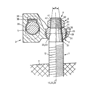
The fixation device depicted in Fig. 1 is meant for
insertion of an implant in the sacral area. Essentially it
consists of a fixation piece or element 1 (here formed as a
pedicle screw), a clamping piece or element 2 which is seated in
connecting piece or element 3, and securing piece or element 6.
The pedicle screw has a conical head section 11 and an
anchoring element 13 (here formed as a thread~ed shaft) adjoining
the head section for fastening into bone 7. In addition, the
pedicle screw has a circular cylinder section 41 with an exterior
threading 42, arranged along its longitll~i n~l axis 12. This
serves as a tension element 4 and permits displacement and
wedging of conical head section 11 relative to clamping element
2. Conical head section 11 tapers down in the direction of its
free end which faces away from the threaded shaft at a conical
angle ~/2 of about 4~.
Clamping element 2 depicted in detail in Fig. 2 has a
conical borehole 21 for form-locking and force-locking
installation of conical head section 11 of the pedicle screw.
Its configuration is that of a spherical shell, and it extends to
both sides of a great circle 23, i.e. a circumferential line
21I6516
,. ~
encircling the clamping piece at its maximum girth. Its
longitll~; nA ~ axis 22 coincides with longitudinal axis 12 of the
pedicle screw as shown in Fig. 1. Since, however, the two parts
1, 2 prior to being reciprocally locked are arranged to be able
to be turned against each other, the two longitll~;nAl axes 12, 22
may deviate from each other over a wide range. Clamping element
2 is provided with slits 24 running transverse to great circle
23; these are arranged to run alternately from above and below.
One such slit 27 is configured to run fully through. I~ one
version which is not depicted, the slits 24 run only from the
side of the larger diameter of conical borehole 21 to great
circle 23.
Connecting element 3 formed in this configuration as a
sacral bucca exhibits a spherically formed--layered borehole 31
for form-locking installation of spherically formed layered
clamping element 2. Longitll~;nAl axis 32 of borehole 31
coincides in Fig. 1 with axes 12, 22. The surface of borehole 31
extends on both sides of great circle 33, so that clamping
element 2 is securely embedded into it and there is no
possibility of it being knocked out in an axial direction 12, 22,
32 from below or above. Spherical borehole 31 also has a sharp-
edged groove 29; this results in improved locking, particularly
if clamping-piece 2 consists of a softer material than fixation
element 1.
As Fig. 3 depicts, spherical borehole 31 of connecting piece
3 formed as a sacral bucca is equipped in its lower openings 34
with two recesses 35 which are configured to be offset by 180~,
2116546
permitting insertion and removal of clamping element 2. For this
purpose, clamping element 2 is turned 90~ so that its
longit~ Al axis 22 is perpendicular to longit~ ;nAl axis 32 of
borehole 31, and its contact surface is aligned to the recesses
35. Clamping element 2 can then be removed from borehole 31
without applying force.
Locking of the fixation device according to the invention is
done by use of an instrument 8 depicted in Fig. 5, which has an
interior thread 82 in its front end. By turning clockwise, the
exterior thread 42 of tension element 4 is screwed into interior
thread 82, until instrument 8 hits clamping element 2, and
thereby fixation element 1 is drawn axially into conical borehole
21. This causes clamping element 2 to be expanded, thanks to its
slits 24, and locked into borehole 31. The s~urface 25 of
spherically formed layered clamping piece 2 or the spherical
inner surface of connecting piece 3 is appropriately roughened,
or possesses a structural design to attain an optimal locking
into borehole 31.
At the same time, of course, the two elements 1, 2 are
locked against each other along their conical surfaces. The
conical angles ~x/2, i.e. of conical head section 11 and conical
borehole 21, both are 4--7-, preferably 3--5-. With a conical
angle ~/2 of this size, an optimal automatic locking and fixation
of the two elements 1 and 2 against each other is effected.
Connection piece 3, formed as a sacral bucca, is in addition
provided with a circular cylindrical channel 36 (Fig. 1), which
forms an angle of 25~ relative to the horizontal plane (as it is
~ ~ ~ 6 5 4 6
'_
defined by great circle 33). A longitudinal outrigger 5 is
placed in channel 36, which can be fixed in any position whatever
by means of set-screw 38 in a borehole 39 which leads to channel
36.
After locking of the individual parts is accomplished, a nut
61 acting as a fastening element 6 with an interior threading 62
corresponding to exterior threading 42 of tension element 4, is
screwed onto circular cylinder section 43.
Fig. 4 depicts a version of the fixation device according to
the invention in which tension element 4 is not attached to
fixation element 1, but rather axially to clamping element 2.
Tension element 4 here consists of a circular cylindrical section
aligned with longitudinal axis 22(a) of clamping element 2. The
circular cylindrical section has an external thread 44. The
conical head section 11 of fixation piece 1 here has an extension
14 in circular cylindrical form.
Reciprocal locking of pieces 1, 2 can be done by means of
the same instrument 8 (Fig. 5), in fact, with a relatively short
interior thread 82. By turning instrument 8 clockwise, exterior
thread 44 is again turned into interior thread 82 until
instrument 8 hits extension 14, and thus the same procedures are
followed as with the design configuration of Figs. 1-3.
To improve fixation, the spherically shaped layered surface
25 of clamping element 2 has sharp edges 28 running parallel to
great circle 23, and the connecting element 3 in this design
configuration is made of a softer material than clamping element
2.
C ,~
5 ~ 6
After locking of the separate elements is done, a cap 63
which serves as a securing element 6 and has an interior thread
64 corresponding to exterior thread 44, is screwed onto circular
cylinder section 43.
As depicted in Fig. 5, connecting element 3 of the fixation
device according to the invention can also be formed as a bone
plate In the four spherically shaped boreholes 31, four
clamping elements 2 are fitted, into which, if need arises, bone
screws in the form of fixation piece 1 according to Fig. 1 can be
fastened.
Fig. 6 depicts a fixation device according to the invention
in the form of a two-sided internal fixator with a set length.
Both ends of connecting element 3 exhibit a spherically shaped
borehole 31 with a clamping element 2 fitted in, into
which fixation element 1 can be inserted and locked in place.
The position of longitudinal axis 12 in both fixation elements l,
thanks to the spherical clamping element 2, is adjustable over a
wide angular range.
Fig. 7 depicts a fixation device according to the invention
in the form of a one-sided internal fixator, which consists of
longitudinal outrigger 5 with a single spherically shaped layered
borehole 31 made on its left side, with a clamping element 2
fitted in. On the right end of longitudinal outrigger 5, a
connecting element 3 analogous to the sacral bucca in accord with
Fig. 1 has been mounted onto longitudinal outrigger 5 and fixed
in detachable fashion onto it by means of set-screw 38, so that
. : ~
., .~;
5 4 6 -
-
it can be slid at will back and forth. Nuts 6 are again provided
to secure the fixation.
Fig. 8 depicts a fixation device according to the invention
in the form of a universal, longitudinally adjustable internal
fixator. It consists of a connecting element 3 analogous to the
sacral bucca according to Fig 1, a square segment 37 and a
similar connecting element 3 with a hollow body 51 possessing a
square-cut interior. The square segment 37 can thus be
longitudinally inserted into hollow body 51 and fixed in any
position whatever by the two set-screws 38. Both connecting
elements 3 exhibit a spherically shaped layered borehole 31 with
clamping element 2 fitted in, in each of which a fixation element
1 can be inserted, locked and secured by means of nut 6.
Instead of a square cross section for the two telescoping
parts 35 and 51, any polygonal or circular cross section can be
chosen. With a circular cross section, the surface of pieces 35
and 51 should preferentially be longitudinally splined, to obtain
a joint which is rotationally stable.
Fig. 9 shows an additional version of a fixation device
according to the invention. In it the conical head section 11 of
fixation piece 1, which is formed as a bone screw, is dimensioned
relatively short. Likewise, conical borehole 21 of clamping
piece 2 which tapers up from below, extends only to a limited
height of the latter, and then expands upwardly as upper conical
borehole 26. The installation of this fixation device is done
essentially identically to the design of Figs. 1-3, simply with a
hollow pin 45 which corresponds to upper conical borehole 26
5 ~ ~
being slid over circular cylindrical section 41, which locks in
similar fashion with axial displacement of elements lf, 2f.
Finally, Fig. 10 shows a version of the fixation device
according to the invention in which conical head section 11 of
fixation element 1, here formed as a bone screw, is not linked
firmly with anchoring element 13, but is formed as a separate
hollow pin. This pin can be slid onto circular cylinder section
41 of tension element 4. The locking mechanism is identical to
that of the design configurations described above.