Note: Descriptions are shown in the official language in which they were submitted.
1
- 1 -
MANUALLY OPERATED VEHICLE LEVELING SYSTEM
BACKGROUND AND SUMMARY
This invention relates to a leveling system for
use with a vehicle, such as a recreational vehicle.
Various systems are known for leveling a vehi-
cle such as a recreational vehicle. Some such systems
are shown in U.S. Patents 4,061,309; 4,165,861;
4,597,584; 4,743,037; and 4,746,133. These patents all
show a leveling system having four jacks located one
adjacent each corner of the vehicle. Schneider et al
U.S. Patent 5,176,391, owned by the same assignee as the
present application, discloses~a vehicle leveling system
,having three jacks, two~of which are located at the
rearward end of the vehicle and one of which is located
at the forward end of the vehicle.
Generally, all of the above-noted patents
disclose vehicle leveling systems which are relatively
complex in construction and operation, to provide auto-
matic leveling of the vehicle in response to certain
operator commands..
It is an object of the present invention to
provide a manually operated vehicle leveling system which
is relatively simple in its components, installation and
operation. A further object of the invention is to
provide a unique jack construction which is especially
suitable for use in a vehicle leveling system such as is
contemplated by the invention.
In accordance with one aspect of the invention,
a vehicle leveling system includes a series of extendible
and retractable jacks mounted to the frame of the vehi
cle, a manually operated actuator mechanism located
within the vehicle interior, and a power system inter-
posed between the jacks and the manually operated actua-
tor mechanism for selectively extending and retracting
the jacks. The series of jacks includes first and second
jacks located toward one end of the vehicle and a third
jack located toward the opposite end of the vehicle. The
CA 02116596 2001-03-09
- 2 -
manually operated actuator mechanism includes a series of
switches preferably disposed in a diamond pattern relative to the
longitudinal axis of the vehicle. The switches may be in
the form of four manually actuated switches mounted to a
panel located in the interior of the vehicle. A level
sensing device is preferably located in the vehicle interior to
provide a visual indication to the operator of the atti-
tude of the vehicle relative to level.
Each jack is preferably in the form of a hy-
draulic cylinder assembly including a cylinder and an
extendible and retractable piston mounted to the cylin-
der. A spring is interposed between the cylinder and the
piston. Introduction of pressurized fluid into the
cylinder causes extension of the piston against the force
of the spring, and the spring causes retraction of the
piston when fluid pressure within the cylinder is re-
lieved. A shoe is connected to the extendible and re-
tractable piston, and the spring is preferably intercon-
nected between the cylinder and the shoe. The power
system is preferably a fluid power system consisting of a
hydraulic fluid reservoir, a pump for selectively supply-
ing fluid under pressure to the jacks from the reservoir,
and a control valve interposed between the hydraulic
fluid reservoir and each jack. Each control valve con-
trols the supply of pressurized fluid to one or more of
the jacks during operation of the pump, and also provides
flow of fluid to the reservoir when the pump is not
operating. The control valves are responsive to opera-
tion of the manually actuated switches for selectively
adjusting the attitude of the vehicle relative to level
in response to manual actuation by the operator. Each
control valve is interconnected with a single return line
interconnected with the reservoir, and a return control
valve is disposed in the return line for controlling flow
of fluid from the jacks to the reservoir. The return
control valve is responsive to a manually operated re-
..~, ~'
- 3 -
tract switch actuable by the operator and located within
the interior of the vehicle.
The invention further contemplates a unique
jack construction for use in the vehicle leveling system
of the invention. A plate is interconnected with the
hydraulic cylinder of each jack toward the upper end of
the cylinder. The spring is interconnected between the
plate and the piston, preferably having its lower end
mounted to the shoe to which the piston is connected. A
- connector arrangement is interposed between the spring
and the plate for securing the spring to the plate. The
connector arrangement is preferably in the form of a
tapered passage provided in the upper end of the spring,
which decreases in transverse dimension in a bottom-to-
top direction, a plug having a tapered wall disposed
within the tapered passage and engaging the spring, and a
connector extending between the plate and the plug. The
plate is mounted to the upper end of the cylinder so as
to be selectively pivotable relative thereto. In this
manner, the spring can be placed in any desired position
relative to the vehicle frame once the cylinder is mount-
ed to the frame in order to avoid any obstructions which
may be present in the vicinity of the frame.
Various other features, objects and advantages
of the invention will be made apparent from the following
description taken together with the drawings.
BRIEF DESCRIPTION.OF THE DRAWINGS .
The drawings illustrate the best mode presently
contemplated of carrying out the invention.
In the drawings:
Fig. 1 is an isometric view of the vehicle
leveling system constructed according to the invention as
installed on the frame of a vehicle such as a recreation-
al vehicle;
Fig. 2 is a partial side elevation view, with
portions in section, showing the interconnection of the
~~~,~~96
,..;
_ 4 _
spring with the cylinder and shoe of each jack in the
leveling system of Fig. 1;
Fig. 3 is a top plan view of the jack of Fig.
2;
Fig. 4 is a view of the manually operated
control panel for the leveling system of Fig. 1; and
Fig. 5 is a schematic representation of the
hydraulic fluid power system of the vehicle leveling
system of Fig. 1.
DETAILED DESCRIPTION OF THE INVENTION
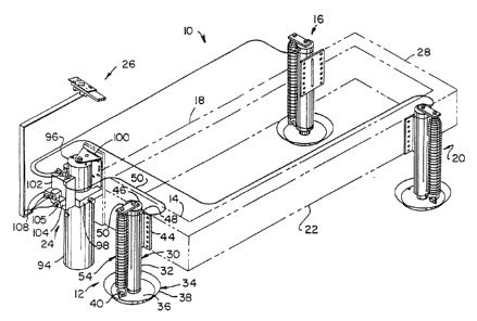
Referring to Fig. 1, a vehicle leveling system
10 constructed according to the invention is mounted on
the frame members of a vehicle, such as a recreational
vehicle or the like. System 10 includes a front jack
assembly 12 mounted to the forward transverse frame
member 14 of the vehicle, a passenger side rear jack
assembly 16 mounted toward the rearward end of passenger
side longitudinal frame member 18, a driver side rear
jack assembly 20 mounted toward the rearward end of
driver side longitudinal frame member 22, a reservoir,
pump and actuator assembly 24 mounted to front transverse
frame member 14, and a manually operated control panel 26
mounted within the interior of the vehicle. Rear jack
assemblies 16, 20 are mounted just forwardly of a rear
transverse frame member 28 which interconnects the rear-
ward ends of longitudinal frame members 18, 22. Front
jack assembly 12 is mounted approximately. at the midpoint
of front transverse frame member 14. This arrangement
pravides a stable three-point leveling system for adjust-
ing the attitude of the vehicle relative to level.
Jack assemblies 12, 16 and 20 are identical in
construction. The construction of jack assembly 12 will
be explained in detail with reference to Figs. 1-3, with
the understanding that such explanation applies with
equal force to jack assemblies 16, 20.
As shown in Figs. 1-3, jack assembly 12 con-
sists of a hydraulic cylinder assembly 30 including a
~2'~. .~'~ ~ ~ ~
- 5 -
cylinder 32 having a piston movably mounted within its
interior. A piston rod (not shown) is mounted to the
piston, and a shoe 34 is mounted to the end of the piston
rod in a conventional manner. Shoe 34 includes a circu-
s lar bottom wall 36 and an upstanding annular angled side
wall 38. A tab 40 having an opening 42 (Fig. 2) is
mounted to the upper surface of shoe bottom wall 36.
A mounting plate 44 is connected to the upper
end of cylinder 32. Plate 44 is provided with a series
of vertically spaced openings adjacent its side edges,
which are adapted to receive bolts or the like to mount
cylinder 32 to frame member 14.
Cylinder assembly~30 further includes a top cap
46 mounted to the upper end of cylinder 32 having a
fitting 48 (Fig. 1) to which a hydraulic fluid line 50 is
connected for selectively supplying pressurized fluid to
cylinder 32 from reservoir, pump and actuator assembly 24
and for providing return flow of fluid from cylinder 32
to assembly 24. Cap 46 further includes a central,
threaded vertical passage opening onto its top surface.
A mounting plate 50 is connected to cap 46
'through a threaded connector 52 which extends through an
opening formed toward one end of plate 50 and into
threaded engagement with the threaded passage formed in
cap 46.
A spring 54 extends between plate 50 and shoe
34.. Spring 54 has a hook 56 at its lower end, which
extends through opening 42 in tab 40 to secure the lower
end of spring 54 to shoe 34. Spring 54 is formed so as
to provide a tapered upper end section 58 defining an
upwardly facing opening, a vertical passage 60 defined by
the uppermost coils of spring 54, and a tapered passage
62 which extends between vertical passage 60 and the
straight-sided vertical passage defined by the coils of
spring 54 below tapered upper end section 58.
A plug member 64 is received within tapered
upper end section 58 of spring 54. Plug member 64 in-
CA 02116596 2001-03-09
- 6 -
cludes a lower section defining a frustoconical outer
surface 66 and a cylindrical upper section 68. A thread-
ed passage extends along the longitudinal axis of plug
member 64 between its upper and lower ends. A threaded
connector 70 extends through an opening formed toward the
outer end of plate 50 and into engagement with the
threaded passage formed in plug member 64 for intercon-
necting tapered upper end section 58 of spring 54 with
plate 50. Connector 70 is turned so as to draw the upper
end of plug member 64 tight against the lower surface of
plate 50 to assume its Fig. 2 position, to provide maxi-
mum pretensioning of spring 54. If desired~to relieve
the pretension of spring 54, connector 70 is turned in
the opposite direction to move plug member 64 away from
plate 50 under the influence of spring 54. Engagement of
frustoconical outer surface 66 of plug member 54 with the
coils of tapered upper end section 58 defining tapered
passage 62 provides positive engagement between plug
member 64 and spring 54. The uppermost coils of spring
54 defining vertical passage 60 further function to
prevent relative movement between plug member 64 and
spring 54 when plug member frustoconical surface 66 is
engaged with the coils of spring 54 defining tapered
passage 62.
If desired, connector 52 can be loosened to
enable plate 50 to be pivoted relative to cylinder 32
throughout a range of movement of approximately 180°, as
illustrated in Fig. 3, in order to allow cylinder 32 to
be mounted to frame member 14 in any desired position.
That is, the pivoting movement of plate 50 provided by
connector 52 allows the installer to place spring 54 in
any position between the range of positions illustrated
in Fig. 3 in order to keep spring 54 out of the way of
any obstructions which may be present on the undercar-
riage of the vehicle adjacent frame member 14.
Fig. 4 illustrates control panel 26 in detail.
Panel 26 includes a planar front wall 72 which is adapted
v,,.;
...
~~Z~~;~6
- 7 -
to be mounted to the dashboard of the vehicle. A series
of manually operable actuator switches are mounted to
wall 72, including a front switch 74, a rear switch 76, a
left switch 78 and a right switch 80. Switches 74-80 are
arranged in a diamond pattern, and panel 26 is mounted to
the vehicle such that the longitudinal axis of the dia-
mond pattern formed by switches 74-80 is parallel to the
longitudinal axis of the vehicle. In this manner, front
switch 74 points toward the front of the vehicle, rear
switch 76 points toward the rear of the vehicle, and left
and right switches 78, 80 point toward the left and right
sides, respectively, of the vehicle.
As an alternative to switches 74-80, it is
understood that any other satisfactory manually operated
actuator mechanism could be used, such as a joystick or
the like.
Control panel 26 also includes a power ON/OFF
switch 82 and an LED 84 adjacent thereto, and a RETRACT
ALL JACKS switch 86. Panel 26 further includes a JACKS
DOWN LED 88, a MOTOR HOT LED 90, and a LOW VOLTAGE LED
92.
Referring back to Fig. 1, reservoir, pump and
actuator assembly 24 includes a hydraulic fluid reservoir
94 and a pump and motor assembly 96, both of which are
mounted to a mounting block 98 disposed therebetween. A
mounting bracket 100 is interconnected with pump and
motor assembly.96 and block 98 for mounting reservoir,
pump and actuator assembly 24 to frame member 14.
A valve block 102 is mounted to block 98, and a
series of supply/return control valves 104, 106 and 108
are mounted to valve block 102. Supply/return control
valves 104-108 are solenoid operated dual poppet bidir-
ectional blocking valves, with a manual override, such as
manufactured by Delta under its Part No. 86020151.
The hydraulic fluid power system for extending
and retracting jacks 12, 16 and 20 as illustrated in Fig:
5 is substantially similar to the hydraulic system as
CA 02116596 2001-03-09
-
shown in Schneider et al U.S. Patent 5,176,391, owned by
the same assignee as the present application.
Similarly, the construction of reservoir, pump and actua-
for assembly 24 is substantially identical to the reser-
voir, pump and actuator assembly as disclosed in Schnei-
der et al U.S. Patent 5,176,391, and reference is made to
the description contained in Patent No. 5,176,391 for a
detailed explanation of the construction of reservoir,
valve and actuator assembly 24.
Referring to Fig. 5, supply/return control
valves 104-108 are located in secondary supply/return
passages 110, 112 and 114, respectively. Valves 104-108
each include a rightward block having a double check
valve and a leftward block providing free flow there-
through. Valves 104-108 are biased toward their position
shown in Fig. 5 in which their rightward blocks are
located in passages 110-114, respectively. In accordance
with known construction, valves 104-108 are shiftable
leftwardly in response to supply of electrical current to
a solenoid in response to operation of switches 74-80.
In the event of an electrical failure, valves 104-108 can
be manually shifted between their rightward and leftward
positions.
Secondary supply/return passages 110, 112 and
114 each communicate with a primary supply/return passage
116, which in turn communicates with reservoir 94 through
a passage 118 and a line 120 extending between passage
118 and a line 122 interconnected with pump 124, which
forms a part of motor and pump assembly 96 (Fig. 1).
Pump 124 is interconnected with reservoir 94 through a
line 126, and is driven by motor 228 which forms a fur-
ther part of motor and pump assembly 96.
A check valve 129 is mounted within passage 118
for providing one-way flow of fluid from pump 124 through
line 120 to primary supply/return passage 116.
CA 02116596 2001-03-09
- g _
A return passage 130 is formed in block 102,
communicating between primary supply/return passage 116
and a line 132 which interconnects with a return line 134
to provide return flow of fluid to reservoir 94 from
primary supply/return passage 116. A return control
valve 136 is provided in passage 134 for controlling
return flow of fluid from primary supply/return passage
116 to reservoir 94. Return control valve 136 is a two-
way normally closed solenoid operated poppet valve, such
as is sold by Delta under its Part No. 85002351. Return
control valve 136 provides a rightward block having a
check valve which prevents fluid flow from primary sup-
ply/return passage 116, and a leftward block having an
oppositely oriented check valve which allows flow in
return passage 130 from primary~supply/return passage 116
to line 132. Return control valve 136 is biased to its
Fig. 5 position in which its rightward block is disposed
in return passage 130. The leftward block of return
valve 136 provides an alternate flow path restricting
arrangement, which in this application is not used.
A series of retraction restricting valves 137,
138 and 140 are located in passages 110, 112 and 114,
respectively between jacks 12, 16, 20 and supply/return
control valves 104-X08, respectively. Retraction re-
stricting valves 137-140 are generally constructed in
accordance with the teachings of Schneider U.S. Patent
4,704,947 entitled "Bidirectional Fluid Flow Valve",
owned by the same assignee as the present application.
Valves 137-140 provide unrestricted flow in
passages 110-114, respectively, during supply of pressur-
ized fluid from primary supply/return passage 116 to
jacks 12, 16, 20, respectively, to extend jacks 12, 16,
20. On the other hand, when fluid pressure in primary
supply/return passage 116 is relieved and flow control
valves 104-108 are shifted rightwardly to provide retrac-
tion of jacks 12, 16, 20, respectively, retraction re-
CA 02116596 2001-03-09
- 10 -
stricting valves 137-140 are shifted rightwardly to
provide a restriction in the return flow of fluid from
jacks l2, 16, 20; respectively to primary supply/return
passage 116, until pressure on jacks 12, 16 and 20 is
relieved to a predetermined extent. In this application,-
retraction restricting valve 137 is shifted to provide
slow retraction of front jack 12 until the front vehicle
wheels engage the ground and relieve pressure on jack 12.
When this occurs, retraction restricting valve 137 is
shifted to its Fig. 5 position to eliminate the restric-
tion in f low through valve 136 and to provide full flow
of fluid thereacross in secondary supply/return line 110,
to provide faster retraction of jack 12. In a similar
manner, retraction restricting valves 138, 140 provide
slow retraction of jacks 16, 20, respectively until the
rear tire set adjacent each jack engages the ground, and
thereafter fast retraction of jacks 16, 20.
Switches 74-80 are interconnected with valves
104-108 to provide selective extension of jacks 12, 16
~ and 20, respectively in response to operation of switches
74-80. Front switch 74 controls extension of front jack
12; rear switch 76 controls extension of rear jacks 16,
20; left switch 78 controls extension of front jack 12
and driver side rear jack 20; and right switch 80 con-
trols operation of front jack 12 and passenger side rear
jack 16.
In operation, to level the vehicle the operator
first actuates power ON/OFF switch 82 to energize the
system, and LED 84 is illuminated to indicate that the
system is energized. The operator then views a level
indicator, such as a conventional carpenter's cross-check
level or a bullseye level to determine the attitude of
the vehicle relative to level. If the front of the
vehicle needs to be raised, the operator actuates switch
74 to extend jack 12. Similarly, the operator operates
switches 76, 78 and 80 to raise either the rear side, the
passenger side or the left side, respectively, of the
CA 02116596 2001-03-09
- 11 -
vehicle until the vehicle has moved to a level attitude.
The operator then actuates power ON/OFF switch 82 to de-
energize the system.
A float switch is provided in reservoir 94 to
illuminate JACKS DOWN LED 88 when any one of jacks 12, 16
or 20 is extended. MOTOR HOT LED 90 is illuminated when
motor 128 has run more than a predetermined period of
time, which indicates that one or more of the jacks is
fully extended and has not reached the ground. LOW
VOLTAGE LED 92 is illuminated if the voltage operating
motor 128 falls below a predetermined level, which indi-
cates that the motor current is above a predetermined
level in order to provide protection for current overload
of motor 128.
RETRACT ALL JACKS switch 86 is actuated by the
operator when it is desired to move the vehicle. Switch
86 is interconnected with retract control valve 136 for
shifting valve 136 rightwardly, and for simultaneously
shifting valves 104-108 rightwardly, in order to provide
retraction of jacks 12, 16 and 20 under the influence of
the spring 54 of each jack.
As in the system disclosed in Schneider et al
U.S. Patent 5,176,391, the system of the present inven-
tion can only be operated when the transmission.of the
vehicle is engaged in its neutral or park conditions and
when the parking brake is engaged. If any one of these
conditions is violated, the electronics of the system
automatically provide retraction of jacks 12, 16 and 20
in.a manner similar to that disclosed in Schneider et al
U.S. Patent 5,176,391.
CA 02116596 2001-03-09
- lla -
Also consistent with the system disclosed in U.S.
Patent 5,176,391, low pressure and high pressure switches
200 and 220, respectively, are mounted to valve block 102,
so as to be in communication therethrough with primary
supply/return passage 116. Low pressure switch 200 is set to
be actuated when a relatively low threshold of pressure,
e.g. 350 psi, is experienced in primary supply/return
passage 116. High pressure switch 220, on the other hand, is
set to be actuated when a relatively high threshold of
pressure, e.g. 2400 psi, is experienced in primary
supply/return passage 116. Low pressure switch 200 is
actuated when jacks 12 - 20 are lowered so as to engage the
ground, to commence the leveling operation. High pressure
switch 220 is actuated when one of jacks 12 - 20 is fully
extended, such as when the vehicle is parked on an excessive
slope or one of the jacks is located over a depression or
the like in the ground.
Various alternatives and embodiments are
contemplated as being within the scope of the following
claims particularly pointing out and distinctly claiming the
subject matter regarded as the invention.