Note: Descriptions are shown in the official language in which they were submitted.
1994-02-07
~ 5 GB 1380
CYLINDER l.OCK - KEY - COMBINATION
The invention relates to a cylinder lock - key - combirlatlon
in accordanae with the preamble of claim 1 and to a key or a
~ey blank provided therefore.
A cylinder lo~k of the kind, provided with turnable locking
discs, has been known as suah already for a long time. Even
if the n~l~her of dif~erent opening combinations available in
this lock type is noticeably great, there has bean a need to
areate ~urther different opening variations so a~ to avoid
coinc~ence~, i.e. 2 key opens by ~ nce a lock it is not
suppo~ed to, which is very rare as such, but esp~r,~ly to be
able to provide loak groups for separate clients including a
~reat number of locks and keys poss~ hl y arranged hierarchical-
ly as ma~eLed locking ~y~L~ ~~
One ~olution is to increase the number of the locking discs
in the lock. The result, how~ver, is that the lock needs more
spa~e in the axial direction thereof and, thus, is in practlce
no longer appl~c~hle to doors or the like obJects of normal
thiokn~ss. Therefore, a more advantageous alternative is ~o
provide di~ferent new key profiles, which are at least partly
but preferably entirely mutually i~ - patible. A known
solution for providin~ new key profiles is d~sclosed in the
patent publication FI 68290, corresp~1ng to US 4127996.
Conventionally ~this lock type has been operated ~y a key the
basic profile of which is ~ icircular in the cross-sectional
plane of the shaft. Therefore and due to manufacturing
techni~ues the possibilities to provide new mutually i n ~ _
patible proflle variations are in practice, however, rather
limited. As the semicircular basic profils in ~uestion has
further been in ~eneral use for a long time, the key security
relating thereto or to key profiles derived therefrom forms
a risk factor, ~ecause by making required additlonal ~roove~
to the key profile~ o~ the keys already in use, they can be
i
~;l6fi~5
i made compatible or operable also with locks intended for only
the new key profiles.
A further profile utilized in the lock type in queskion has
a somewhat rectangular cross-sec:tion. This verslon, however,
relates to a specific bidirectic~nally operable cylinder lock
provided wi-th turnable locking discs, cf. for instance the
patent publication FI 74320, correspo~ng to US 4351172. In
this arrangement returnlng of tlhe loaking discs take~ place
by means of one or more re~urn bars movable at ~he periphery
thereof and to which ~orce transmission ~rom the key is ac-
shed through a so called li~ting O-lo~k~n~ disc.
Relating further to this lock version the patent publication
FI 81429, correspond~ng to US 4686843, disclo~es a separate
guidins Pl f - ~ to be inserted in the key r,h~n"el, the purpose
of which is together with rotation limlting means to prevent
inadvertent S~L hllng o~ the stack of locking discs by
guidin~ disp~ of the key into the lock and out from the
lock so tha~ it can take place only in a certain turning
position. A further purpose for the guiding element is to
i 3~e picking of the lock. In addition by varia~ing the form
of the guiding el~ ~t new key pro~iles can be ~c~ ~lished.
In this solution the guiding ~lement, however, does not at all
; act directly on the locking discs themselve~
The publication WO 89/11014 disclo.ses ~lU,el a solution based
on the oonv~nLional ~e ~ nl rcular key pro~ile and in whiah the
~ 7' n~tion surfaces as well as the return surfaces providing
returning of the locking disc~ are located conventionally on
the plane side o~ the key shaft. In addition this arrangement
includes two bars fixed to the lifting O-locking dlsc, of
which one is lo~ated in th~ key ~.hannel itself. The~e bars
together return the locking discs when the key is turned back
towards the locked position of the lock mechanism. ~he purpose
of also this arrangement is to prevent picking of the lock by
preventing probing and displacement of individual locking
discs by means of a picklock. Otherwise returning of the
, . .
23~6~
locking discs takes place in normal use of the lock mechanlsm
by means o~ the key in a quite conventional way.
An aim of the invention is to pro~vide new profile variations
for the baslc lock type referred above, operable in one
direction and provided wi~h turnable locking discs, by means
of a new solution, in which a guiding element known as such
a~d to be located in the key ch~rl~el is made use o~ so that
the advantage~ of the previous solu-tions are achieved but the
disa~van~a~es thereof are ~ n~ted. At the same time an aim
is to provide such new key profiles, by means of which key
security perta~ n~ n~ to this lock type can be improved.
I'he aims of the invention are achieved ln a way ~ crl o~e~ more
clearly in the claim 1 and in the other claims. In accordance
with the invention the stack of discs includes a number of
locking discs, the key opening of which is so formed that it
comprises at least one step ext~n~ng towards the central part
of the key opening and the ad~acent sides of whi~h being
substantially perp~n~ lar with regard to each other, whereby
one side of the step forms a combination surface arranged to
cooperat~ with a corr~sp~n~ n~ combination surfsce in the key
for de~el ~nln~ the turning ~ of the locking disc with
regard to the inner cylinder when the key is turned in the
opening direc~ion of the lock ~ch~n~ sm, and the other si~e
of the step respectively forms a return surface for the
locking disc on wh1ch the key is arranged to act by means of
the guiding els -~t for returning the locking disc into a
locking position of the lock mechanism correspon~ng to the
initial inserting position of the key. Thus, by utili~ing a
new kind of c~in~tion of the key opening of a locking disc,
and of the key profile and returnin~ of the locking dis~s by
means of a guiding element located in the key channel, a new
basic profile and new surfaces therein can be made available
for providing profile variation.
The extent of the return surface in a locking dis~ need not
b~ as large as that of a combination surface~ Therefore in
-' 21 t 61~ ~ r;
practiae it is sufficient that the length of the return
surfac~ in the key opening of the locking disc i9 only below
a third of the !- '~in~tion surfac~ of the locking disc. Hereby
more space is obtained in the ke~ shaft for such surfaces that
can be availed of for profile variation.
The key opaning of locking disc is with advantage designed
so that it includes a curved surface extend1ng ~rom one end
of the return surface and arranged at the position of the
region for the possible cuttinys for the peripheral no~ches
in the locking disc, sald curved surface being formed and
positioned so that the distance bstween a cut peripheral notch
and the key opening is preferably at least 1 mm. Hereby it is
secured that the reglon between the peripheral notches and
the key opening L.- .-in~ sufficiently wide in view of manufac-
turing and strength of the looking disc.
The guiding element preferably comprise~ two ~ e~tending
~mmetrically on both sides o~ the key ~.h~nn~l in the a~ial
dire~tion W,e-eof, whereby the ke~ op~ n~ of the lockin~ disc
comprises, correspo~n~ly, two separate 3~eps each including
a return surface arranged to cooperate wi~h elther one of the
axial r~ ~rs Of the guiding element. Hereby, for its part,
it is secured that the key can be inserted in the ke~ ~h~nPl
in t~o separate positions with 180~ turning angle with regard
to each o~her.
In practice ~n advantageous embodiment i5 achieved so that a
profile disc turnabl~ with the key of the lock and limiting
tha key ~h~nel iS arranged between the cylinder houslng and
the inn r ylinder at the inser~ion end of the key, whereby
said guiding el r -nt is supported to said profile disc. The
key opening of the profile disc can then be ~y~ ~tically
variated for provision of different lock-key-familias based
on different key profiles.
In order to increase profile vari2tions and for providing an
i ~_uved support ~or said guiding element it is ~upported to
~' 21~6~
a O-locking disc, known per se, arranged along the key channel
at the inner part of the inner cylinder, whereby the key
opening of sald O-locking disc can b~ variated independent on
said profile disc for further defining key pro~iles conform-
ing to and operable in the lock.
A key or a k~y blank included in the c ~n~tion according to
the invention ls with advantage formed so ~hat the ~haft part
thereof has at least substantial:Ly rectangular cross-~e~tion
and compri~es at least one groove, preferably two grooves
located symmetrically on aither side of ~he shafk, exten~l n~
lengthwlse over the ~hafk for said guiding element. The shaft
part of the key or of the key blank comprises further an edge
and in ~so~ation ~ ..lth a slde plane, starting ~rom which
the comb~nation surfaces detexm~ n-i n~ the opening co~bination
of the loc~ in each case are arranged to be cut as bevelled
surfaces to be arranged a~ selec~ed intervals from each other
towards another edge in the shaft part l.ocaked adjacent to ~he
said first edge, said second ed~e being essentially rounded~
~ereby the compatibility of the key with the lock is secured
and at the same time it is po~ hl e. to ~L~V~ the use of keys
with c . -k ~ ar profiles in ~he lock in question, which
es key s~curity.
In addition the key comprises with advankage two series of
~ combination surfaces located symmetrically on opposite sides
of the center a~ls of th~ shaft part of th~ key, whereby the
edges of the shaft part of the key located ad~acent to said
series of l_ ~;n~tion surfaces are rounded. Hereby the key can
be inserted in the lock in two different turning pos~tions as
described abov~ and the lock be turned op~n from ~ither of
these position~, which is con~enient for the user. If then the
key includes only one series of combination surfaces, more
possibilities are achieved for profile variations but at the
expens~ of said convenience.
The invention will now be further described, by way of
~ ~le, with ..,~feJence to the a: wnying drawings, in which
211660~
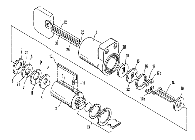
- figure 1 shows an exploded view of an embodiment of a
cylinder lock - ~ey - comblnation according to the
invention,
- figure 2 shows a normal locking disc included ~n the
combination of ~igure 1,
- figure 3 shows a prof~le disc to bs utilized in a lock for
the l '~in~tion according to ~le invention, and in addition
some possible proPile variatiLon arrangements are illus-
trated by dotted lines,
- figure 4 shows a so called lifting 0-locking disc to he
utili~ed in a lock for the combination according to the
invention, and in addition ~ome posslble profile variation
arrangements are illustrated by dotted lines,
- figure 5 shows a cros~-sect~onal view of the basic pro*ile
of a key included in the combination according to the
invention including also the possible combination cuts,
- figure 6a shows a cross-sectional view of the prvfile of
the key at the position of the profile disc according to
figure 3 included in the lock~ and ~igure 6b shows
respectively a cross-sectional view of the profile of the
key at the position of the lifting O~loc~ing disc according
to figure 4 included in the lock.
In the drawings 1 1 n~ c~es a cylinder houxing having a
turnable inner cylinder 2 ~ n~ ~e. thereof. ~he inner cylinder
2 ~.n~.l O~Q~ a stack of discs, which 1 nr l u~es a number of normal
locking discs 4 ~urnable with a key 12 of ~he lock and having
a key opening 7 and a peripheral notch 20 dete- 1 n ~ n~ the
opening combination of the lock ~ch~ni ! , and at least one
lifting 0-locking disc 3 having a key opening 6. The locking
discs are separated from each other by means of intermediate
discs 5 having a key opening 8. The lock mechanism includes
also a locking bar 10, which in the loc~ed position of the
lock mechanism is located par-tly in a groove 30 in the
cylinder housing 1 and partly in a slot 9 in the inner
cylinder preventing turning of the inner cylinder 2 with
regard to the cylinder housing 1. The locking discs can be
turned with the key 1~ of the lock into a position, in which
the peripheral notches 20 form at the position of the slot 9
of the inner cylinder 2 in the axial direction of the lock a
lln~ fC channel, into which the locking bar 10 enters from the
groove 30 in the cylinder housing 1 thereby releasing the
inner aylinder 2 to turn together with the key with regard to
the cyllnder housing 1. This turning v, -nt of the inner
cylinder 2 is transmitted ~urther to some desired member, for
instance to a lock bolt. In figure 1, 13 indicates generally
means, with which the inner cylinder 2 with its stack of discs
is axially locked to the cylinder housing 1 and by means of
which force transmission ~rom the inner cylinder 2 can take
place.
As i~ yenerally know in this lock type the lock mechanism
operates under posltive g~ nc~" whereby the lift~ng 0-
loaking disc is a-~ng~d to press the locking bar lO back into
~he groove 30 in the cylinder housing 1 when the lock
-ch~n1l is locked. In this ~o~nection a ~pring 11 is used
for assisting said ,~ of the locking bar 10 and thus for
making the operation smoother.
The lock includes also a guiding Pl~ - ~ 14 located in the ke~
~h~nnel ~ormed jointly by the ~ey openings 6, 7 and 8 in the
discs of the stack of discs. In the embo~ ~L of figure 1 the
guiding el~ L 14 comprises two members exten~n~ axially on
both sides of the key ch~nne~ over the stack of disc~ and
being oonnected together at the inner end of the key chan-
nel. The shaft of the key 12, respectîvely, has grooves 25
for the guiding element 14~ In the case of figura 1 the
guiding element 14 is su~poL~ed at the inner end of the inner
cylindsr 2 to the lifting 0-locking disc 3 and at the outer
end thereof, respsctively, to the profile disc 15. The both
discs 3 and 15 turn continuously with the key when the key is
turned in the look, whereby returning of the locking discs is
carried out unconventionally by means of the groove 25 of the
key, the discs 3 and 15 and the guiding ~ 14 so that the
guiding element 14 acts on a counter surface 23 made in the
key cpening 7 of the locking discs 4 (cf. figure 2).
The lock of f igure 1 includes also a drill resisting member
19 and limitiny members 16 and 17 whlch are advantageous from
the viewpoint of undisturbed o~eld~ion of the lock by allowing
insertlon of the key 12 into the lock and removal ~I-e-~o~ only
in a certain position. Thus, they ~Levent inadvertent scram-
bling o~ the stack of discs, and together with the guiding
el~- - t 14 they prevent wear of the lock caused especiall~ by
insertion and L~ -~Vd~ nts o~ the key when the lock ls
operated. In practice said limitation can be arranged through
different means. In this case limiting plates 17a and 17b are
supported to a sleeve 16, which is stationarily supported to
the inner cylinder 2. When the key is turned ln the lock
lim~ting plates 17a and 17b move radially towards the shaft
of the key 12 and by means of rec~ss~ 31 made therein ~Lav~n~
removal of the key from the lock until the key is turned back
to its inltial position corresponding to the insertlon
position. A plate 18 ~upports the limiting members 16 and 17
from inside of the lock.
Figure 2 shows a normal locking disc 4 included in the lock.
The key opening 7 of the locking disc 4 has two symmetrlcally
arranged steps 21, which include combination surfaces 22,
which cooperate with ~ n~tion sur~aces 27 to be cut in the
key (cf. figure 5), and return surfaces 23, which, when the
key is returned to the inltial posltion after unlocking the
lock ~ch~n; sm, under the influence oi the guiding element 14
cause turning of the locking disc~ 4 back to their initial
position correspon~i n~ to the locked position of the lock
~ ch~n~ sm as described above. The key opening 7 has also a
curved surface 24, which is formed so that the distance A
between the key opening 7 and the peripheral notches 20 is
sufficient in view of manufacturing techniques and strength
requiL - Ls, i.e. the distance A is preferably at least 1 mm.
Figure 3 shows a profile disc 15 to be utilized in the lock
according to the invention and a key opening 32 of which is
made use of to provide desired profile variations in the key
-,,,,,," ~ '' ' '",",, ' ~ ,'','';''.,'''
-' 2~660~
shaft, which is shown with dotted lines in figure 3. Thus,
long profile grooves extRn~in~ over the whole shaft of the key
are ~ h~ to the key sha*t through the profile disc 15.
In addition also short grooves can be arranged to the key
shaft by making use of also the key opening 6 of the lifting
O-locking disc in a way known as such, as is shown in figure
4 respectively~ The key profiles corresponding to the profile
disc 15 according to figure 3 and to the O-locking disc
according to figure 4 are shown in figures 6a and 6b.
In the embo~ of figure l the lifting O-locking disc 4 is
the ~nne~ di9c in the stac~ of discs in the inner cylinder
2. Thls is not n~ce~s8~ry from the viewpoint of the opera~ion
of the lock - '- n~ , but when desired the lifting O-locking
disc can be moved outward in the sta~k of discs and, thus,
longer.profile grooves can be provided to the key shaft for
provision of further proflle varia~ion~3. Naturally also the
form and size of the g~ooves can be variated accordin~ ~o
need.
As espe~~ y a~a~en~ from figu~e 5 the key is with advantage
provided with two series of combination surfaces 27, the
cut~i~g of which is started from a rather acute edye 26 and
a side 33 in ~soc~tion therewith so as to secur~ a suffiA
cient effeotive surface for the combination surface. The
adjacent edges 28 for ~he edges 26 are rounded by taking
account of the requirements for the design of the key op~n~ n~
7 as referred above. At the same time it should be observed
that the ~ n~tion surface 27 to be cut in the key shaf~ can
be made sufficiently long so as to secure a r~ h~e ~ a~ion
of the lock 3~.h~n; ~.
The invention is not limited to the embodiments shown, but
several modifications are feasible wi~hin the scope of the
attached claims.