Note: Descriptions are shown in the official language in which they were submitted.
21 1 7421
-1-
MICROSCOPY SYSTEM
TECHNICAL FIELD
The invention relates to microscopes and more
specifically to a high magnification microscopy system with
improved high resolution and depth-of-field at 6,000X
magnification and greater.
BACKGROUND ART
In medical microscopy the objective is to get three
things, as good a resolution as possible, as much
magnification as you can resolve, and the best depth of field
as possible. These objectives in the design of optical
systems generally require compromises. In a standard optical
microscope the depth of field is inversely proportional to the
magnification. As the magnification gets higher the depth of
field gets narrower. If the object being viewed is
sufficiently small that you have to magnify it to the point
your eye can see it, the depth of field gets so narrow that
there is no contour to what you are looking at and it blurs
since there is no depth of field.
Another aspect in terms of microscopy is the fact that up
until a few years ago blood was believed to be sterile. It
was thought there was no fungus or bacteria in blood except
under severe pathological conditions. Today, systemic
micro-organisms in the blood have changed the early thinking
that blood was sterile. The discovery of AIDS has resulted in
a complete new understanding of the immune system of opportune
organisms that take advantage of a depressed immune system.
The standard research microscope cannot be used to study
organisms because they are too small. In these microscopes
the power of magnification is about lOOOX or 1500X. Some
sophisticated systems are available where you can get 2000X,
and 2500X, but the depth of field gets so narrow they are only
used for research. What is needed for examination of blood
for its organisms is magnification in excess of 5000X. Also
the depth of field must be sufficient that the total contour
of the organisms can be seen. To give a general idea of the
problem, if a person wants to see a red blood cell they need a
'~
. ~
- 21 1 7421
-2-
depth of field of at least 7 microns. If the depth of field
drops to 3~ microns, it is only possible to see half the red
blood cell. As the depth of field becomes progressively less,
a person can only see a slice of the blood cell. If the
interest being researched relates to membranes and things of
this sort, a different approach has to be taken to break out
of the limitations of a standard optical system.
Another important criteria that hadn't been looked at is
most research microscopes concentrate on what is known as dark
field microscopy. The problem is how do you illuminate and
contrast what you want to look at? Also what type of light
source could be used to try to enhance the contrast? Some of
the new microorganisms need to be studied and are not seen in
dark fields. It is therefore necessary to go to other types
of optical modes, like phase contrasts, polarized light, as
well as dark fields. This gets into things like differential
interference phase. These are different ways of enhancing
different types of light. As it turns out, it is necessary to
do all of the three or four types of optical modes in addition
to increasing magnification and depth of field. Due to the
physics of optics, you can only get so much magnification if
you want to maintain some sort of depth-of-field. It was
determined that optimal magnification must be around 400X
instead of lOOOX. Therefore in order to gain the degree of
required magnification necessary for visible analysis, it was
determined that projection magnification could be used in
conjunction with the initial optical magnification. A unique
microscopy system has been designed by the applicants to
combine a projection lens with the research microscope after
it has received its optical magnification. The extra
magnification produced by the projection lens does not affect
the depth of field as the beam spreads out. The projected
- image may be received by a video camera and it is moved either
toward or away from the projection lens in order to vary the
amount of magnification. The resolution lens of the camera
thus becomes a limitation. As better cameras and camera
systems are developed, the resolution can be increased in the
21 1 7421
higher priced camera. It is important that the candle power
required to illuminate the object has to be greater than what
is presently used with research microscopes. The best
microscopes on the market today have approximately 80 watts of
illumination. This is clearly insufficient when we are
talking about magnification levels of 10,000 or greater. It
is therefore necessary that the light source be in the order
of 150 watts of light so that there is in the order of 100
candle power available by the time the object is being viewed.
When the T.V. camera is used it also requires so many candle
power of lumens in order to get full color out of the camera.
In order to be able to use cheaper projection lenses, the
system has been designed to only use the central flat portion
of the lens which is substantially of the same quality for
expensive lens and cheaper lenses.
It has been found that the basic system works quite well
with a halogen white light 150 watts bulb. Since such a bulb
would give off too much heat if positioned beneath the
specimen platform, it has been necessary to locate the light
source in a remote housing with its light being directed
through a fiber optic cable whose exit end is positioned
beneath the specimen platform. This is highly important
because when it is desirable to look at live blood, extreme
heat will destroy the organisms in the blood. Electron beam
microscopes will go to 250,000X and they use an electron beam
for resolution so that they have good resolution and high
magnification. The problem is that you destroy the live blood
specimen when it is under normal conditions on the specimen
platform. A condenser lens is used at the front end of the
fiber optic cable to focus the beam. This allows the system
to be changed from one optical mode to another, such as, dark
field, bright field, phase-contrast, single side band
differential interference phase-contrast, and polarized and
neutral density bright field.
The projection lens positioned in the bottom end of the
projection tube allows the light to come out at about a thirty
degree angle, but the only portion worried about is the center
,~
21 1 7421
-4-
portion and the remainder is absorbed in the interior of the
projection tube. Since the projected image is received on the
camera lens the movement of the camera upwardly and downwardly
in the projection tube will vary the magnification. When the
camera is lowered to its lowest position, the magnification is
that of the optical magnification system. When the camera is
raised to its highest position, its magnification can go up as
high as 12,000X with a 150 watts light source, but its depth
of field remains unchanged between its lowest and highest
positions since that has been determined entirely by the
optical magnification, and not by the variable projection
magnification. This opens a whole new window in medical
microscopy because now small microorganisms can be seen with
their alterations or destruction in the membrane integrity.
The camera will produce whatever it sees in the tube housing
on a video monitor at a size up to 40 times greater,
depending on the size of the monitor. The depth of field on
the video system remains constant.
The limitations and resolution relates to the light
source that is used. The closer one comes to monochromatic or
single wave length light the better the resolution will be.
If higher magnification is required and better resolution
necessary, it would simply be a matter of going to a laser
type of light.
DISCLOSURE OF INVENTION
The novel microscopic system has been designed to combine
an optical magnification portion and a variable projection
magnification portion. The optical magnification occurs
through the objective magnification lenses that form the basic
structure of a research microscope. The variable projection
magnification is produced in the projection tube and by a
moving camera connected to a video monitor.
A light source housing containing a high intensity light
such as a 150 watts bulb has its light directed through
fiberoptic cable into the base of the microscope with the
front end of the fiberoptic cable being mounted in a collar
having a condensing or collimating lens positioned in its top
' ,~
21 1 7421
opening. The light that passes through the condensing lens
then travels upwardly through the specimen platform and the
slide mounted thereon. The image projected upwardly through
the objective magnification lens is then passed to the
projection lens at the top end of a tubular member attached
to the optical housing of the research microscope. The entire
amount of optical magnification occurs up to and including the
projection lens so that any further magnification beyond the
projection lens does not affect the depth of field. As the
image passes through the projection lens it is dispersed and
magnified. Only the portion of the image in the center of the
projection lens is being viewed. This is what is seen on the
lens of the T.V. camera mounted thereabove. The remainder of
the projected image is captured by the interior of the
blackened walls of the projection tube. By operating the
motor connected to the top end of the T.V. camera, the T.V.
camera can be made to move upwardly or downwardly thus varying
the amount of projection magnification. The variable
projection system of the T Vo camera itself magnifies the
image to the resulting size that is seen on the video monitor.
The video monitor can also be connected to a VCR or a video
printer. It would also be possible to replace the T.V. camera
in the projection tube with a photographic plate for capturing
the projected image.
The prior art is limited by a finite number of
magnification steps, a limited amount of available light for
imaging, existing light sources damage samples with
corresponding heat, limited depth of field, spherical
aberations, close proximity of sample-to-objective lens
distance, diffraction effects from finite sized lens elements,
and field resolution from low quality lenses. The objects and
advantages of the novel microscopy system are: 1) continuously
variable magnification for each objective lens allowing
optimization for sample size, 2) a high intensity light source
coupled by fiber optic cable provides sufficient light without
damage to the sample, 3) constant depth of field for a
variable magnification, 4) reduced spherical aberations by
.~
21 1 7421
using only the flat center portion of the imaging and
projection lens, 5) increased resolution with constant depth
of field, 6) reduced diffraction effects by elimination of
lenses, 7) objective lens to sample distance increased by
allowing magnification to occur elsewhere (above projection
lens), 8) projection length determined by shape of projection
lens, 9) imaging medium provides additional magnification, 10)
variable projection magnification is independent of type or
nature of light source, and 11) variable projection
magnification is independent of imaging medium.
BRIEF DESCRIPTION OF THE DRAWINGS
FIG. 1 is a front perspective view illustrating the
components of the novel microscopy system;
FIG. 2 is a block diagram of the components of the novel
microscopy system; and
FIG. 3 is a vertical cross sectional view of the
projection tube mounted on the optical housing.
BEST MODE FOR CARRYING OUT THE I~V~N-110N
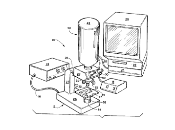
The novel microscopy system is generally designated
numeral 10 and it will be described by referring to FIGS. 1-3
of the drawings. The major components of the microscopy
system 10 are research microscope 12, light source housing 14,
fiber optic cable 16, power unit 18, video monitor 20, VCR 22,
and video printer 24.
Microscope 12 has a base 26, a post 27, an arm 28, and an
optical housing 29. Viewing eye pieces 30 and a plurality of
objective power magnification lenses 32 are connected to
optical housing 29. A collar 34 mounted on the top surface of
base 26 has a condensing lens 35 mounted in its top end. A
specimen platform 37 has a slide 39 positioned thereon.
Projection housing or tube 40 is mounted on the top surface of
optical housing 29.
Projection housing 40 has a tubular member 42 having a
top cover plate 43 and a bottom plate 44. An adapter collar
46 mounts projection housing 40 on the top end of optical
housing 29. Tubular sleeve 48 of microscope 12 passes
upwardly through adapter collar 46 and it has a projection
'~
2 1 1 74~ 1
-7-
lens 50 mounted in the eyepiece of the microscope. T.V.camera 52 is supported by camera backplate 53 that is attached
to motor support block 54. Electrical cable 55 connects
camera 52 to video monitor 20. Motor 56 is mounted on motor
support rod 58 whose top end is journaled in top bearing rod
support 60. Motor support rod 58 freely passes through an
aligned bore hole in motor support block 54. A bearing block
57 is also attached to camera backplate 53 and bearing block
57 has a bore hole that allows it to freely travel up and down
the bottom end of motor support rod 58. A pair of laterally
spaced vertical support shafts 62 insure the alignment of
motor 56 as it travels upwardly and downwardly along motor
support rod 58. Electrical cable 59 connects power unit 18 to
motor 56. Projection lens holddown plate 64 has an aperture
through which projection image passes and also bore holes that
allows it to be raised and lowered on members 58 and 62.
Position indicator plate 68 has a LED support bracket 69
connected to its front end which has LED 70 mounted therein.
The rear end of position indicator plate 68 is secured to a
transverse support plate 71 that has a pair of spaced bore
holes that allows it to travel up and down the vertical
support shafts that are located on both sides of said T.V.
camera 52. As camera 52 travels upwardly and downwardly LED
70 is visible through vertical slot 72.
'.~