Note: Descriptions are shown in the official language in which they were submitted.
ROUND B~L~R PIC~UP INC~DIN~ ~INED R~ VIN~ ~TI~F ~T~
Backqround of the Invention
Th~ pr~sent invention relates to crop harvesting
implements having pickup a~tachments ~or lifting windrows of
crop materials to crop processing elements of the implements
an~ more particularly r~lates to the teeth of such pickups as
are used ~or conveying crop to the baling chamber o~ an "open
throat" large round baler, l.e., one that does not use any
compression rolls through which crop passes o~ its way to the
baling chamber.
The f~e~in~ oE crop into round balers of "open throat"
design during the initiation of bale formation has long posed
a problem. This is because these open throat baler~ rely on
the growing or forming bale in the baling chamber to help feed
the crop into the baler. Thus, until the bale starts to roll,
tha feeding of crop to the baling chamber comes almost totally
~rom the pickup device. This requires extra care by the
operator to avoid plugging the baler during the first few feet
o~ forward travel. It is particularly important to be careful
to avoid getting crops caught at or near the end~ o~ the
pickup device, b~aause part o~ the windrow occasionally
~xtend~ beyond the end of the pickup. This creates an extra
volume of crop to be fed into the baler at the ends of th~
pickup~ Unfortunately, it is fairly common for this situation
to occur during bale ~tarting because, in the typical case,
the operator o~ th~ tractor pulling the baler has backed up
the baler to ~i~ch~rge a just-completed bale and upon driving
~orward after such ~is~hArge approaches the windrow at an
angle. ~ust a~ typically, in order to form a bale having a
good shape, an operator will intentionally drive the tractor
in a weaving pattern so that the trailing baler moves back and
Porth relative to the windrow for th~ purpose of A~1ng more
crop to an end of the bale which is smaller than the other
end. A~ter ~isrh~rge of such a bale, the baler may still be
positioned for feeding crop at that end o~ the pickup where
fee~;n~ was taXing place when the previous bale was fin;she~.
Another factor which contributes to difficult bale
starting is the orientation or sti~ness o~ crop stems, as
well as the slipperiness o~ crop against the bale-forming
belt~. This i~ so because, if the incominq crop is di~ficult
to flex or grip compared to normal crops, it is relatiYely
difficult to have the crop begin rolling up on it~elf. Thi5
would be analogous~ for axample, to the relatlve ease of
rolling up a flexible carpet or ~leeping bag as oppos~d to
ro~ling up a sti~fer bed mattress or a slippery, stiff sheet
of plastic.
Summary o~ the Invention
lo According to the present inventlon there i~ provided a
pickup improved for ~eeding heavy crop at the end~ of the
pickup and Por e~ecting initiation o~ the formation o~ a bale
in the baling chamber oP a round baler having an open throat.
A broad object of the invention is to provide a crop
harvesting implement with a pickup having at least some teeth
which are stiffer than conventional teeth ~or maintaining a
~mooth, even crop flow into crop processing elements of the
implement.
A more ~pecific object of the invention is to provide a
harves~ing implement with a pickup, as set forth in the
previous ob~ect, wherein teeth at opposite end portions of the
pic~up are essentially in~lexible during normal operating
conditions.
Yet another object o~ the invention is to provide a
pickup ~or a large round baler wherein the pickup has teeth
considerably sti~fer than those conventionally associated with
a baler pickup so that a more positive and even ~low of crop
occur6 which aids in the initial roll up of crop during bale
Pormation and also in reducing plugging.
The~e and other objects will h~c~ ? apparent from a
re~d1 nq of the ens~ing description together with the appended
drawings.
Brie~ Description of the Drawinqs
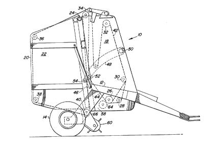
FIG. 1 is a right side elevational view of a larg2 round
baler with which a pickup constructed in accordance with the
present invention is particularly adapted for use.
~4~i i!i 10
FIG. 2 is an enlarged sectional view showing the baling
chamber receiving crop Eor starting a bale.
an inlet at the bottom of an expansible baling chamber deliver
FIG. 3 i~ a perspective view of the pickup spider~ and
tooth bars showing an embodiment where ultra-sti~ t~eth are
mounted at end portions o~ the tooth bars togPther with stif~
te~th in the central portions o~ the bars.
Description of the Pre~erred Embodiment
Initially, it is to be noted that various components are
described as existing in palrs while only one of each pair is
shown and it is to be understood that the un~hown compon~nt is
the same or similar in construction to the o~e shown.
Referring now to FIG.l, there i~ shown a baler 10 of the
type for making large cylindrical bales and commonly called a
large round baler. The baler ~0 comprises a main frame 12
supported on a pair of ground wheel~ 14 and having a draft
tongue 16 secured thereto and adapted ~or being connected to a
tractorO A pair of transversely spaced vertical sid~walls 18
is joined to the frame 12 and ha~ respective upright rear
ends. A bale discharge gate 20 including opposite sid~ walls
22 is vertically pivotally attached, as at 24, to upper rear
locations of the sidewalls 18, the sidewalls 22 having ~orward
ends which abut against th~ rearward ~nds o~ the sidewalls 18
when the gate 20 is in a lowered closed position as shownD
The pairs of idewalls 1~ and 22 rotatably upport the
opposite ends of a plurality o~ bale-forming belt support
rolls adjacent the periphery o~ the ~idewalls. Specifically,
beginning at a lower central location of the sidewalls 18 and
proc~e~ counterclockwise, there are mounted a driven roll
26, a lower ~ront roll 28, an intermediate front roll 30, an
upper *ront roll 32, and an upper rear roll 34; and continuing
counterclockwise from an upper rear location of the gate
~idewalls 22 there is mounted an upper rear roll 36, a lower
rear roll 38 and a lower front roll 40. A plurality of
endless bale-forming belts 42 are spaced one from the other
across the space between the opposite pairs of ~idewalls 18
and 22. Except for ~ome of the belts 42 which skip the lower
Lront roll 28, the belts are trained so that they serially
engage the rolls ~6, 28, 30, 32, 36, 38, 40 and 34. A ~ront
run 44 of the belts ~ extends upwardly Prom driv~n roll 26 to
the roll 3~. Similarly, a rear run 4~ o~ the belts 42 extends
upwardly from the lower front gate roll 40 to ths roll 34.
Mounted ~etween rear end locations of a pair of rearwardly
ex~en~ing tensioning arms ~8 which are vertically pivotally
mounted, as at 50, ~o a mid-height location at the front of
the sidewall~ 18 are closely spaced, front and rear idler
rolls ~2 and ~. The front and rear runs 44 and 4~ of the
belts 42 respectively converge upwardly from the drive roll 25
and lower ~ront gate roll 40 and pas~ closely to each other
between the rolls 52 and 54, with the run 4~ contacting a r~ar
surface of the front roll 52 and with ~he run 46 contacting a
~orward sur~ace of the rear roll 54. The runs 44 and 46 thus
coop~rate with the sidewalls 18 and 2~ to de~ine a baling
chamber 56 which is closed at its top by the idler rolls 52
and 54 and, as viewed in vertical cross section from the side,
is wedge-shAre~. The bottom o~ the chamber 56 is provided
with an inlet 58 (see also P'IG. ~) exten~i ng between the
driven roll 2~ and the lower ~ront gate roll 40. Crop
products are introduc~d into the inlet 58 by a pickup 60 ~or
being roll~d into a bale 62 (shown only in FIGSo 2) by the
action oP the ~ront and rear runs 44 and 46 o~ the belts 42,
which are respectively driven ~o as to kravel toward and away
from the inl~t, ~nd initially also by a starter roll 64
rotatably mounted in ~he sidewalls 18 adjacent to and being
driven in the same direction as the driven roll 26 so that it
operates to strip crop being carried downwardly by the front
run of balts 44. As the bale 62 is being formed, khe chamber
56 yieldably ~Yp~n~.~ against the force established in the
belts by a tensioning ~ystem includin~ the pair of ten~ioning
arms 48 kogether with spring~ and hydraulic cylinder~ (not
~hown) coupled between the walls 18 and the arms 48 for
re~isting upward movement of the armq~ Once the bale 62
reaches a certain size, the weight thereof is horne ~ainly by
che lower frollt ga~e roll 40 but also by the driven roll 26
and the starter roll 64.
Referrin~ now al~o to FIGS. 2 and 3, it can be seen that
the pickup 60 ha~ a frame 66 pivotally mounted to the bal~r
frame 12 for moving or being adjusted about an axis, which in
this case is coincident with the axis o~ ro~ation of the lower
frdnt gate roll ~0~ The pickup frame 66 is shown in the upper
range of it~ movement or adjustment. The pickup 60 inrlude~ a
tined reel structure 67 including a central drive shaft 68 of
hexagonal cross sectlon on which a pair of spiders 70 are
fixedly mounted at transversely spaced locations. The spiders
70 each have four equi-angularly spaced arm~ and tooth ~ar~
72, formed of angle iron, extend between timed arm~ of the
pair of spiders and are pivotally mounted thereto by
cylindrical pin~ 73 that are releasably bolted to the opposite
ends o~ each tooth bar and pivotally received in bores
provided in each pair of timed arms. Secured to each tooth
bar 72 at transversely ~paced location~ therealong are ~pring
testh 7~ 9 each including a coiled inner part bolted to the
angle iron and a pair of tines 75 exten~i ng o~twardly ~rom
opposite ends of the inner part, as is conventional. Each
group of four teeth 74, re~pectively mounted to a oommon
location of the four tooth bars 72, have first and second sets
oP coplanar tines 75. A U--~haped stripper a~sembly 76 opens
rearwardly and comprises separate ~trippers 78 in the form of
bands loaated between each set of coplanar tines 75 of each
yroup of four teeth 74 so that slots are Eormed between
ad~acent strippers for permitting ~ree travel o~ the tines
therethrough. A~ viewed from the side, each stripper 78 has a
forward ~emi-cir~ular no~e portion joined to upper and lower
parallel legs, with a rear end o~ the upper leg being bolted,
as at 82, to an upper, flat transverse surface 84 of the
pickup Erame ~6, and wi~h the lower leg being boltedl as at
86, to a lower, flat transverse surface 88 of the ~rame 66.
Provided ~or effecting controlled rocking motion o~ the tooth
bars 72 and hence de~ired motion of the tines 75 a~ the tooth
hars 72 revolve with the shaft 68 and spiders 70 is a cam
assembly including arms 90 re~pectively welded ~o the outer
ends of the pins respecti~ely secured to the right ends o~ the
~our tooth bars 72. Mounted to each of the arms 90 is a cam
roller 92 received in an endless, inwardly opening,
substantially D-shaped track 94 o~ a cam 96 that i~ bolted to
a leftt upright side (not shown) o~ the pickup ~rame 66. As
th~ rollers 92 travel along the track 94, they cause the tovth
bars 72 to be rocked so as to cause the outer ends of the
tines 75 0~ the teeth 74 to ~race a path indicated at ~8. It
lo can be seen tha~ a~ ~he teeth 7~ reach the top or twelve
o'clock position of their travel ~he tines 75 are caused to
swing forwardly so that a major component of the m~v~ -nt of
the tinss is downward as the tines are withdrawn below the
plana of the upper legs of the strippers 78D
To this point the description has been that o~ a
conventional baler and pickup. However applicant~s pickup is
not conventional because the keeth 74 and hence tines 75 are
much ~ti~er than conventional teeth.
Specifically, one known conventional tooth has the
following stiffness:
(a) spring rate per tine = 1.44 in-lb per degree of
defleation; and
(b) tip force perpendicular to the tine = 9 lbo at 41
degrees of deflection.
It i3 thought that no one in the industry has teeth having a
spring rate in excess ~f 2 in-lb per degree. Applicant's
teeth 74 hava the following stiffness:
~a) spring rate per tine 75 = 3~96 in-lb per degree of
de~lection; and
(b) tip Porce perpendicular to the tine 75 = 25 lbs. at :~
41 degrees o~ deflection.
Thus, the teeth 74 are about twice as ~tif~ as the stiffest
teeth thought to be in use and ~re about 2.5 times the
~ti~ness o~ the known conventional teeth.
The ~ollowlng field te~ts were made comparing the
operation of a baler equipped with a pickup having
conventional teeth with the known tooth stiffness, ~et ~orth
- - ~
above, and a similar second b~ler aq~ipped with a pickup
having teeth with the stiffness of the t~th 74, per the
above:
1, During a 13 hrO day baling wheat ~traw, the baler
with the teeth 74 was able to produce 26S bal~s
while the other baler was able to produce only 18g
bales. Thus, the baler with the teeth 74 achi~vad a
40% increase in productivity ov~r th~ other baler.
The operaticn of thes~ two balers in various
o conditions and crops over se~veral days resulted in
the baler with the teeth 74 achieving from 15-2~%
increase in productivity over the other baler in
producing a total o~ 4000 bales.
2. During a more limited te~t baling sweet cane
sorghum, a first baler having a pickup equipped with
the teeth 74 was able to e~fectively start 100% o~
12 bales attempted while a second baler equipped
with conventional teeth was not abl.e to ~tart any
bales~ In another test in baling sorghum, the baler
e~uipped with conventional teeth had great
diffiaulty in starting bales, even with special
operating techni~ues while balers equipped with khe
stif~er teeth did not experience any difficulty in
starting bales~
3. During baling grass and legume silage bal~s, the
baler having a pickup equipped with the teeth 74 had
les~ di~iGul~y in ~tarting bales than did the baler
having a pickup aguipped with conventional teeth.
Furtharmora, there was no t~n~nCy, in the baler
having its pickup equipped with the stiff teeth, for
the crop to wrap about the starter roll (only
one wrap in 600 bale~) which was con~idered very
good performance since this baler wa~ not equipp d
with a starter roll scraper for preventing wrapping
as wa~ the b~ler having the pickup equipped with the
conventional teeth, such scraper being con~idered
nece~s~ry ~guipment ~o prevent wrapping.
Thus, the above test~ tend to show that the stiff teeth
74 are superior to conv~ntional teeth in th~ starting of bales
in di~-Eicult crops and in productivity, iOa., ~'through putllo
Further, the tests tend to show that the stif~ teeth 7~ feed
dif~i~ult silage crops with little tendency for the crops to
wrap on ~hQ ~ar~er roll. Although, only one size o~ sti~f
to~th was used in the tests indicated above, it is thought
that a tooth exhibiting a tip ~orce o~ at least 19 lbs. at 41
degrees of de~lection wo~ld also greatly enhance bale starting
and ~ee~in~ when opera~ing in di~ficult crops.
Referring now to FIG. 3, there is shown a slight
variation in the pickup 60 whera the sti~f teeth 74 are
a~ n; ed by very stiff or ultra-sti~f te~th 1on having
tines 102. These teeth 100 are about many times stiffer than
conventional pickup teeth and are at least ten times, and may
be thirty times, stiffer than the tines 75 of the stif~ teeth
74. Thus, the tines 102 are essentially in~lexible under
normal operating conditions. While these teeth 100 are shown
with a coiled inner portion, it has been ~ound that U shaped
teeth made of bar stock without coils may also be used to
enhAnc~ operation.
As illustrated, one tooth loo is mount~d at each end o~
each tooth bar 72 9 with the teeth 74 being mounted along the
center portion the tooth bar 72. The purpose of the teeth loo
is to make the feeding at the ends o~ the pickup 60 more
positiv~ or aggressive since, as ~tated above, it is
particularly important to avoid the hesitation o~ crop to feed
during the bale starting process as ~uch hesitation leads to
plugging and such hesitation u5ing conventional pickupc almost
always occurs at or near the ends o~ the pickup device when
extra crop extends beyond the end of the pickup and, thus, :
creates an extra volume of crop to be fed into the baling
~h~ h~r . If such agressive ~ee~;~g over a wider section o~
the ends o~ the pickup is desired, more taeth 100 may be used
at each end. Further it has been found that in some crop
conditions feeAin~ may be e~h~nce~ by intermiyin~ the teeth
100 with the teeth 74 across the middle portion of the pickup.