Note: Descriptions are shown in the official language in which they were submitted.
CA 02117819 2002-03-04
HEMMING PRESS
Field of the Invention
This invention relates to hemming sheet metal and more particularly
to an apparatus for forming a hem on an edge of a sheet of a structural sheet
member such as a vehicle body panel.
Background
Door, hood, and trunk deck lids of vehicles have been formed of one
unitary outer skin of sheet metal joined around its periphery to a second
inner
reinforcing panel of sheet metal by hemming a generally unturned flange along
each edge of the outer sheet over an adjacent edge of the inner panel.
This hemming has been accomplished in two separate stages. Prior
to performing the first stage, the reinforcing panel is nested within the
outer panel
fixtured on an anvil die on a base of a prehemming machine. Upon fixturing the
assembly, a tool of the machine, commonly referred to as a hemming steel,
engages and bends an edge of the outer panel to an acute included angle with
respect to the outer panel. After the prehemming of all edges to be joined,
both
panels are released, transferred to and fixtured in a second hemming machine
where a second tool completely bends the prehemmed edge of the outer panel
over
the peripheral edge of the reinforcing panel to secure and attach the panels
together as a unitary structural member for assembly on a vehicle.
CA 02117819 2002-03-04
Typically, a plurality of both prehemming and final hemming
machines are respectively grouped around the periphery of a panel to perform
all
prehemming and hemming operations for one assembly either sequentially or
substantially simultaneously. This type of hemming process and equipment has
proven to be commercially successful and is still in widespread use.
However, this hemming process has disadvantages. Such a two-stage
hemming process is costly and inefficient by requiring multiple components,
namely, a prehemming machine, a transfer mechanism and a final hemming
machine to perform the entire hemming assembly operation. Additionally, a
considerable amount of tooling and transfer equipment is required for this
type of
process, it consumes a great deal of valuable manufacturing floor space and it
increases the likelihood of equipment malfunction which can undesirably delay
production. Furthermore, the process requires numerous steps to completely hem
a single component. For example, the assembly must be fixtured, prehemmed,
released, transferred, fixtured and final hemmed resulting in a low finished
part
production rate. Finally, this two-stage process requires a relatively larger
sheet
flange depth which increases component weight and cost.
This two-stage process is also susceptible to quality control
problems. During transfer to the final hemming station, the panels may loosen
from each other, become skewed with respect to each other, or not be properly
located with respect to the final hemming station resulting in a finished
hemmed
assembly of lesser quality and poor structural integrity. An assembly with
these
2
CA 02117819 2002-03-04
characteristics may have to be repaired or scrapped, thereby increasing
production
costs and lowering profits. Even worse, an ill-assembled structural member
with
these flaws, if incorporated into an assembled vehicle may fit poorly and
affect
perceived quality by prospective purchasers, thereby reducing vehicle sales
and
profits. An assembled defective structural member may further lose integrity
as
the vehicle is subjected to road vibration during use and possibly require
replacement and negatively impact an owner's figure vehicle purchasing
decision.
More recently, hemming machines have been designed which
perform both the prehem and final hem operation in a single machine tool
station
which eliminates the need for a complex transfer mechanism. Hemming machines
of this type vary in the kind of mechanism used and the manner of carrying out
the
hemming operations. Representative of these hemming machines are U. S.
Patents:
Kollar et al 3,191,414; E. R. St. Denis 3,276,409; Dacey Jr. 4,706,489; and
Dacey
Jr. 5,083,355.
The hemming machines embodied in the Kollar '414 and E. R. St.
Denis '409 patents are of similar construction and operation. Both patents
disclose
a pair of fluid powered drives earned by a frame of the machine fox driving a
single hemming steel through both the prehem and final hemming stages. Each
machine utilizes one drive to control the sideward motion of the hemming tool
toward the anvil and sheet during the prehem operation and a second drive for
downwardly moving the tool to clinch the flange in a hem overlapping the
structural reinforcing panel.
3
CA 02117819 2002-03-04
A disadvantage of these single station prior art machines is that the
hemming tool or steel continuously contacts the sheet edge during both stages
of
bending the flange which may produce undesirable distortion and highlighting
in
the sheet. A further drawback is that failure to maintain precise actuation
sequencing of the first and second drives during hemming may result in the
outer
panel being defective hemmed to the reinforcing panel causing the costly
scrapping of the assembly. Furthermore, they have an abrupt motion of the
hemming steel due to cam drives and high actuation forces. Also, the equipment
to accurately sequence the actuation of each drive adds to the complexity of
the
machine, requiring additional costly maintenance while reducing reliability.
Finally, the sequencing complexity of this type of hemmer limits the number of
assemblies which may be produced during a given period of time.
Dacey, Jr. '489 discloses a hemming machine utilizing a single drive
and hemming steel connected by a complicated system of linkages and a cam and
follower arrangement to perform both the prehem and final hem operations.
Dacey, Jr. '355 discloses a hemming machine having dual drives and a single
hemming steel connected by a linkage and eccentric shaft arrangement to
perform
both the prehem and final hem operations.
A shortcoming of these prior art machines is that the hemming tool
follows an arcuate sideways path, literally "wiping" the flange while
prehemming
the sheet edge which can introduce unwanted distortion or highlights in the
outer
4
CA 02117819 2002-03-04
panel adjacent the hem which are visual even after finishing and painting it.
Moreover, the outer panel bends immediately adjacent the edge of the inner
panel
rather than at a predetermined desired brake point which results in
undesirable
variations and inconsistencies from one panel assembly to another. The drive
and
sequencing mechanism is also complicated and requires frequent and costly
production-delaying adjustments and is prone to unacceptable wear limiting the
machines commercial usefulness.
Summate of the Invention
A press for prehemming and final hemming a sheet received on an
anvil with separate prehemming and final hemming tools or steels each driven
through linkage powered by the same prime mover, such as a cylinder or a screw
and servo motor. Each steel is mounted on a separate carrier or subframe
pivotally
mounted by links in a main frame and each driven through separate toggle joint
assemblies to produce the force far bending the sheet by the steels.
Preferably, to
ride a more compact structure, the prehem subframe is also eccentrically as
well
as pivotally mounted on the main frame. Preferably, the toggle joint
assemblies
are connected through rocker arms to the prime mover and the linkage provides
a dwell in the movement of the prehemming steel so that it does not interfere
with
movement of the final hemming steel.
In another embodiment of this invention, to provide a simpler, more
inexpensive prehem linkage with a more compact structure while being able to
5
CA 02117819 2002-03-04
more precisely control prehemming steel speed, acceleration and dwell as well
as
the clearance between the two steels during press operation, the prehem toggle
joint assembly operably connects the final hemming steel subframe to the
prehemming subframe and prehemming tool for more accurately synchronizing the
prehemming tool with the final hemming tool.
Objects, features and advantages of this invention are to provide a
combined prehemming and hemming press which eliminates highlights, provides
a consistent break point in the outer panel, produces a hem with improved
tolerances, requires only one prime mover to drive both the prehemming and
hemming steels, utilizes mechanical linkage to sequence and synchronize the
movement ofboth steels, enables speed, acceleration and dwell ofthe prehemming
steel to be more precisely controlled allowing the use of larger steels to hem
more
complexly contoured workpieces, enables a contoured workpiece to be hemmed
about its periphery using a minimum of hemming presses, is of relatively
compact
construction making it easier to transfer panels into and out of a hemming
press
of this invention, is of relatively simple design, compact construction and
arrangement and is rugged, reliable, durable, stable during operation, of
economical manufacture and assembly, has a long useful life in service and
requires relatively little maintenance and repair in use.
G
CA 02117819 2002-03-04
Brief Descriution of the Drawings
These and other objects, features and advantages of this invention
will be apparent from the following detailed description, appended claims and
accompanying drawings in which:
FIG. 1 is a fragmentary side view of a hemming press embodying
this invention.
FIG. 2 is a fragmentary front view of the hemming press of FIG. 1.
FIG. 3 is a top view of the hemming press.
FIG. 4 is a kinematic diagram illustrating a prehemming tool and
drive linkage of the press in a retracted position.
FIG. 5 is a fragmentary sectional side view of an anvil supporting
a panel assembly and the prehemming tool in the retracted position of FIG. 4.
FIG. 6 is a kinematic diagram illustrating the prehemming tool and
its drive linkage in an extended position.
FIG. 7 is a fragmentary sectional side view of the anvil supporting
the panel and the prehemming tool in the extended position of FIG. 6.
FIG. 8 is a kinematic diagram illustrating a. final hemming tool and
its drive linkage in a retracted position in solid lines and in an extended
position
in phantom lines.
FIG. 9 i s a fragmentary sectional side view of the final hemming tool
adjacent the prehemrned edge of the sheet on the anvil.
7
CA 02117819 2002-03-04
FIG. 10 is a fragmentary sectional side view of the final hemming
tool in a final hem position having formed a return bend in the outer sheet
and
forced the flange into overlapping engagement with the edge of the inner sheet
of
the panel assembly received on the anvil.
FIG. 11 is a fragmentary side view of a screw drive and servo motor
operably connected with a crank arm of the hemming press of FIG. 1.
FIG. 12 is a fragmentary side view of a second hemming press of
this invention.
FIG. 13 is a kinematic diagram of the second hemming press
illustrating the prehemming tool in a retracted position and its drive linkage
both
in an extended position shown in solid lines and in a retracted position shown
in
phantom lines.
FIG. 14 is a kinematic diagram illustrating the prehemming tool in
an extended position.
Detailed Description of the Invention
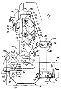
Referring in more detail to the drawings, Figs. 1-3 illustrate a
hemming press 20 embodying this invention with a prehemming tool 22 and a
hemming tool 24 for prehemming and final hemming an upright flange 26 along
an edge 28 of a sheet metal panel 30. The edge 28 to be hemmed is supported by
an anvil 32 fixed to a main frame 34. Each tool or steel 22 & 24 I received on
a
separate carrier or subframe 36 & 38 assembly mounted on the main frame 34.
8
CA 02117819 2002-03-04
Each steel 22 & 24 is driven by a separate toggle joint assembly 40 & 42, both
of
which are powered by a single prime mover 44, such as a fluid actuated
cylinder
assembly.
A single press 20 may be used to produce a finished hem along an
edge of a single sheet or an edge of an outer panel of a nested assembly 46 of
inner
48 and outer panels 50. However, frequently either twa or four of these
presses
are arranged around the periphery of a sheet 30 or panel assembly 46 to either
sequentially or simultaneously hem either two or four peripheral edges of the
sheet
30 or assembly 46.
Frame
As shown in Figs. 1 and 2, the main frame has two pairs of upright
inner 52 and outer 54 or long and short upstanding support plates fixed at
their
lower ends to a base or a base plate (not shown). The prehemming subframe 36
is mounted on the inner plates 52 and the final hemming subframe 38 is mounted
on all of the plates. Preferably, the anvil 32 is also supported by all of the
plates.
For some applications, usually to facilitate insertion in, removal from
and transfer of the panels through the press 20, it is pivotally mounted so it
can be
tilted by stub shafts fixed to the outer plates 54 and received in a cradle-
like base
(not shown).
9
CA 02117819 2002-03-04
Prehemming Tool
The prehemming steel 22 extends longitudinally of the length of the
flange to be hemmed 26 and, as shown in Fig. 1, has a horizontally projecting
lip
58 with a downwardly and inwardly inclined face 60 v~rhich in use bears on the
flange 26 to bend it over an adjacent portion of the sheet 30, usually to an
acute
included angle of about 35° to 55° and preferably about
45°. Preferably, the face
60 is inclined downwardly and inwardly at an angle of about 45 ° to the
horizontal.
Preferably, to limit the extent to which the steel 22 can be advanced toward
the
anvil 32, it is constructed so that its bottom edge bears on a shoulder 62 in
the
anvil 32 when the steel 22 is fully advanced by the press 20.
Prehemmin~ Subframe
In use, the steel 22 is secured by cap screws 64 to a mounting plate
66 of the subframe assembly 36. The mounting plate 66 is fixed such as by
welding to a pair of spaced apart and parallel side plates 68. The subframe 36
is
pivotally mounted on the main frame 34 for movement in. a generally arcuate
path
by a pair of torque tubes 70,72 journalled for rotation by bearings 73
received in
the side plates 68 and eccentrically mounted for pivotal movement on the main
frame 34. Each tube 70, 72 is eccentrically mounted by stub shafts 74
journalled
in bearings carried by the inner support plates 52 of the main frame. So that
the
torque tubes 70, 72 can be rotated in unison to advance and retract the
subframe
36 and steel 22, a pair of spaced apart arms 76, 78 is fixed to each tube and
10
CA 02117819 2002-03-04
connected by a link 80 and pivot pins 82 received in the arms.
To provide the desired arcuate motion for the steel 22, as viewed in
Figs. 1 and 4, the eccentric pivot point for each stub shaft 74 of the tubes
70, 72
is in the lower right hand quadrant of the tube when the prehemming steel 22
and
subframe 36 is in the fully retracted or raised position.
A second embodiment of a hemming press 20' of this invention is
shown in Figs. 12-14, and which also has the prehemming subframe pivotally
mounted on the main frame 34 by a pair of torque tubers 70', 72' for
facilitating
movement of the prehemming steel 22 in a generally arcuate path. The
prehemming subframe assembly of press 20' is essentially the same as press 20
except, for simpleness and compactness of construction, only the upper torque
tube
72' has an arm 168 fixed to it for being driven by the prime mover 44 during
press
operation.
This arrangement of torque tubes, locatian of the eccentric pivot
points, connecting arms and links provides a compact arrangement for mounting
the prehemming subframe and steel. However, where a less compact arrangement
is acceptable, a single torque tube could be utilized by locating the
eccentric pivot
points of its shaft in the upper right hand quadrant as viewed in Figs. 1 and
4. This
would eliminate the second torque tube 72 and the interconnecting link 80 and
arms 76, 78.
11
CA 02117819 2002-03-04
Prehemming Toggle Joint Assembly
The subframe 36 and steel 22 are driven through a toggle joint
assembly 40 which provides a mechanical advantage multiplying the force
applied
to the flange 26 of the sheet 30 as the steel 22 approaches its fully advanced
position. The toggle joint assembly 40 has a pair of spaced apart arms 84
fixed to
a shaft 86 journalled for rotation on the upright inner plates 52 of the main
frame
34 and pivotally connected by a pin 88 to one end of a link 90, the other end
of
which is received between and pivotally connected by a pin 92 to one end of a
pair
of arms 94 fixed to the lower torque tube 70.
Referring once again to Figs. 12-14, the subframe 36 and
prehemming steel 22 of press 20' are driven through a toggle joint assembly
40'
that is in operable communication with the final hemming subframe 38 for more
directly synchronizing movement of the prehemming steel 22 with the final
hemming steel 24 while, preferably, resulting in a press 20' of more compact
construction and lower vertical profile making it easier to transport panel
assemblies into a hemming work station. The toggle joint assembly 40' of press
20' functions essentially the same as toggle joint assembly 40 of press 20 in
translating movement of the prime mover 44 into movement of the prehemming
steel 22 while replacing shaft 86, arms 84, and link 90 :in direct
communication
with the prime mover 44 with linkage directly connecting the final hemming
subframe 38 to the prehemming subframe 36 for providing a prehemming
subframe 36 and toggle joint assembly 40' of reliable and stable operation. By
12
CA 02117819 2002-03-04
driving the prehemming steel 22 through linkage directly operably connected to
the final hemming subframe 38, both the prehemming steel 22 and final hemming
steel 24 accelerate and decelerate at the same time during press operation
making
it easier to synchronize their movement and prevent them from interfering with
each other.
The toggle joint assembly 40' has at least one first link 170 pivotally
fixed to the main frame 34 adjacent one end by pin and bearing assembly 142
journalled in a bushing 140 and between its ends is pivotally connected by a
pin
138 to one of the side plates 130 of the final hemming subframe 38. Adjacent
its
opposite end, the first link 170 is pivotally connected by a pin 172 to a
second link
174 which in turn is pivotally connected by another pin 176 to the arm 168 of
the
upper eccentric 72'.
As is shown more clearly in Figs. 13 & 14, the first link 170, second
link 174 and eccentric arm 168 never become aligned during operation for
preventing the prehemming toggle joint assembly 40' from becoming unstable,
thereby ensuring that the movement of the prehemming tool 22 is synchronized
with the final hemming tool 24 so the press 20' does not jam andlor the steels
don't
collide with each other. Preferably, if desired, the lengths ofthe first link
170 and
second link 174 may be varied relative to each other to adjust the dwell,
speed and
acceleration of the prehemming steel 22 as it moves toward and away from the
anvil 32 of the press 20', control the clearance between the prehemming steel
22
and final hemming steel 24 during operation, and enable larger hemming steels
to
13
CA 02117819 2002-03-04
be used to extend further inwardly over the anvil 32 and panel 30 when hemming
a panel 30 having a rather complex contour along its outer periphery without
th
steels colliding with each other. For example, to reduce the speed of the
prehemming steel 22 as it approaches the anvil 32, the length of the first
link 170
can be reduced.
Drive Assembly
The toggle joint assembly 40 is powered by a drive assembly 44
having a single fluid, preferably air, actuated cylinder 96 connected through
linkage to the toggle joint assembly 40. A piston rod 98 of the cylinder is
connected by a clevis 100 and pin 102 to one end of an arm 104 fixed to a
drive
torque tube 106 journalled for rotation by a pair of stub shaft and bearing
assemblies 108 mounted on the outer plates 54 of the main frame 34. The toggle
joint assembly 40 is operably connected with the torque tube 106 through an
arm
110 which is fixed at one end to the torque tube 106 and at the other end
pivotally
connected by a in 112 to one end of a link 114, the other end of which is
pivotally
connected by a pin 116 to one end of the pair of arms 84 fixed to the shaft 86
of
the toggle joint assembly 40. The housing of the cylinder 96 is pivotally
mounted
on the inner plates 46 of the main frame 34 by stub shaft and bearing
assemblies
118 and a yoke 120 secured to the housing.
To avoid interference and provide clearance between the
prehemming 22 and the hemming 24 steels, preferably the prehemming steel 22
14
CA 02117819 2002-03-04
dwells in its retracted position while the hemming steel 24 is in its extended
position, as shown in Fig. 1. This dwell is provided by the arcuate or
circumferential location of the arm 110 on the torque tube 106 relative to the
toggle joint assembly 40 when the piston rod 98 of the cylinder 96 is fully
extended. With these components disposed in the position shown in Fig. 1, so
that
the axis of the arm 110 extends at an angle of about 15 ° below a line
through the
centers of the main tube 106 and the pivot pin 112, the prehemming steel 22
substantially dwells through about 30° of rotation of the torque tube
106 and arm
110 by the cylinder 96.
As is shown in Figs. 12-14, the toggle joint assembly 40' is powered
through the final hemming subframe 38 by the prime mover or drive 44. To avoid
interference and provide clearance between the prehemming 22 and hemming 24
steels, the prehemming steel 22 dwells in its retracted position while the
hemming
steel 24 is in its extended position during final hemming of the flange 26,
preferably such as is shown in Figs. 12 & 13. This dwell is provided by the
construction and arrangement of the first link 170, second link 174 and
eccentric
arm 168 of the toggle joint assembly 40'. With these components disposed in
the
positions shown in Figs. 12 & 13, the prehemming steel 22 will dwell when the
piston rod 98 of the drive 44 is in its fully extended (shown in solid line in
Fig. 13)
and retracted (shown in phantom in Fig. 13) positions.
15
CA 02117819 2002-03-04
Final Hemming Tool
The final hemming steel 24 extends longitudinally the full length of
the flange 26 to be hemmed and has a preferably slightly arcuate bottom face
122
which bears on the prehemmed flange 26 and bends it to the final fully hemmed
position (Fig. 10), as the steel 24 is fully advanced by the press 20.
Preferably, the
steel 24 is removably received on a spacer plate 126 which is secured to a
mounting plate 128 of the subframe 38.
Final Hemming_Subframe
As shown in Figs. 1 and 2, the mounting plate 128 of the subframe
38 is fixed to the upper end of the subframe. The subfrarne 38 has a pair of
spaced
apart and parallel side plates 130 fixed by welds to spacer plates 132
disposed on
their front edges.
The subframe38 is pivotally mounted on the main frame for
generally arcuate movement by four link assemblies 134.. Each link assembly
has
a pair of spaced apart arms 136 pivotally connected adjacent one end by a pin
138
to one of the side plates 130 and fixed adjacent the other end to a bushing
140
journalled on a pin and bearing assembly 142 mounted on each pair of inner 52
and outer 54 plates of the main frame 34.
The final hemming subframe 38 of press 20' is essentially the same
as press 20 except that at least one of the upper links 136 of the upper link
assemblies 134 have been replaced with first link 170, as is shown in Fig. 12,
16
CA 02117819 2002-03-04
which extends beyond pin 138 for transmitting movement of the final hemming
subframe 38 to the prehemming subframe 36 through toggle joint assembly 40'.
In all other respects, the final hemming subframe 38 of press 20' is and
operates
the same as the final hemming subframe 38 of press 20.
Final hemming Toggle Joint Assembly
The final hemming subframe 38 and steel 24 are driven through a
pair of toggle joint assemblies 42. Each toggle joint assembly 42 has an arm
146
fixed at one end to the main drive tube 106 and adj acent the other end
pivotally
connected by a pin and bearing assembly 148 to one end of a pair of toggle
links
1 S0, the other ends of which are pivotally connected by a pin and bearing
assembly
152 to one of the side plates 130 of the subframe.
Press Operation
In a hemming cycle of the press 20, initially the piston rod 98 of the
cylinder 96 is fully retracted which places both the prehemming steel 22 and
the
final hemming steel 24 in their fully raised and retracted positions. The
assembly
46 of an outer panel 50 with an upturned flange 26 along an edge to be hemmed
28 over an adjacent edge of a reinforcing panel 48 nested therein is deposited
on
the anvil 32. Usually, a fixture is utilized to accurately locate the panel
assembly
on the anvil 32.
17
CA 02117819 2002-03-04
The prehemming operation is initiated by energizing the cylinder 96
to advance its piston rod 98. The hemming tool 22 and subframe 36 are moved
downwardly in a generally arcuate path to bear on and bend the flange 26 from
the
position shown in Fig. 5 to that shown in Fig. 7 by movement of the drive
linkage
and toggle joint assembly 40 from the position shown schematically in solid
line
in Fig.4 to that shown in Fig. 6. As the toggle joint assembly 40 moves to its
mid
point position (Fig. 6), it provides the maximum multiplication the force
produced
by the cylinder 96 and applied to the steel 22 as the steel approaches its
fully
extended position to complete the prehemming bend of the flange 26.
To prevent distortion and highlighting of the panel adjacent the hem
during bending, the curve of the generally arcuate movement of the steel 22 is
designed to substantially eliminate relative sliding motion between the flange
26
and the inclined face 60 of the tool 22 as it forces the flange 26 into its
prehemmed
position. This is accomplished by constructing and arranging the eccentric
mounting of the subframe 36 to produce a path of movement of the steel 22
complementary to that of the flange 26 during bending about its desired break
point.
After the prehemming bend is completed, the steel 22 is retracted by
continuing advancement of the cylinderpiston rod 98 which continues to rotate
the
arm 84 of the toggle joint assembly 40 clockwise (from the position shown in
Fig.
6) to the position shown in phantom in Fig. 4. This movement of the toggle
joint
assembly 40 rotates the carrier torque tubes 70, 72 clockwise which raises and
18
CA 02117819 2002-03-04
thereby retracts the subframe 36 and hence the steel 22 along the generally
arcuate
path to its fully raised or retracted position.
The prehemming operation of press 20', as is illustrated more clearly
by the kinematic diagrams in Figs. 13 & 14, is initiated by energizing the
cylinder
96 to advance its piston rod 98 from the position shown in phantom in Fig. 13
toward the position shown in solid line to move the prehemming steel 22 from
its
dwell position, to permit unloading and loading of a panel assembly 46 onto
the
anvil 32, to an extended position (Fig. 14), where it bends the flange 26 of
the
panel to a prehem position, and later return the steel to a dwell position to
permit
the final hemming steel 24 to final hem the flange 26.
As the cylinder 96 rotates the torque tube 1 U6 clockwise, its arm 146
and toggle links 150 lower the final hemming subframe side plates 130 about
pivot
points 142. With the movement of the side plates 130, the first link 170 of
the
prehem toggle joint assembly 40' rotates clockwise about pivot pin and bearing
assembly 142 from the position shown in phantom in Fig. 13 toward the position
shown in Fig. 14 moving the prehemming steel 22 in a generally arcuate motion
toward the panel 46 and anvil 32. When the first link a 70 reaches the
position
shown in Fig. 14 and is substantially aligned with the second link 174, the
toggle
joint assembly 40' provides the maximum multiplication of force produced by
the
cylinder 96 and applied by the steel 22 as it engages the flange 26 and bends
it to
the prehem position.
19
CA 02117819 2002-03-04
With further rotation of the torque tube 106 toward the position
shown in solid line in Fig. 13, the prehemming steel 22 is retracted from the
anvil
32 toward the dwell position shown to provide clearance for the final hemming
steel 24 to move toward the anvil 32 and engage the flange 26 to complete the
hem.
By the advancement of the cylinder rod !~8, the subframe 38 and
hence the final hemming steel 24 is also lowered or advanced in a generally
arcuate path from the solid line to the phantom line positions shown in Fig. 8
to
bear on the prehemmed flange 26 and bend it into the fully hemmed position,
shown in Fig.lO, to form a return bend with the flange 26 overlying and firmly
engaging an edge 154 of the inner panel 48. As shown in Fig. 8, the clockwise
rotation of the drive tube 106 moves the toggle joint assemblies 42 from the
solid
line position to the phantom line position in which the toggle joint
assemblies 42
approach their respective mid points m to thereby lower or advance the steel
24
to its fully extended position. As the toggle joint assemblies 42 approach
their mid
point position m, they produce the greatest multiplication of the force
produced
by the cylinder 96 and applied to the steel 24 as the steel approaches its
fully
advanced position to complete the bend and force the flange 26 into firm
engagement with the underlying edge 154 of the reenforcing panel 48 to
complete
the hem 156.
To prevent distortion and highlighting of the panel during final
hemming, even though the carrier 38 and steel 24 move in an arcuate path, as
the
20
CA 02117819 2002-03-04
flange 26 approaches its fully hemmed position (Fig. 10), the associated
segment
of the path is substantially at a right angle to the plane of the final fully
hemmed
position of the flange 26 and there is substantially no relative lateral
movement
between the flange 26 and the face 122 of the tool 24 bearing the flange 26.
This
is achieved by the construction and arrangement of the pivotal link assemblies
134
so that (as shown in Fig. 8) when the steel 24 approaches the fully hemmed
position, there is substantially no lateral movement of tile subframe 38 and
steel
24 due to the portion of the arc in which the pivot link assemblies 134 are
moving
in which (as shown in phantom Fig. 8) the longitudinal axis through their
pivot
points extends substantially parallel to the plane of the flange 26 when in
its fully
hemmed position.
After the finished hem is completed, the steel 24 is retracted by
actuating the cylinder 96 to move its piston rod 98 to the fully retracted
position.
This rotates the main tube 106 counter-clockwise (as viewed in Figs. 1, 4, 6,
and
8), which through the associated linkage and toggle joint assemblies, retracts
and
raises both carriers 36, 38 and their associated steels 22, 24 to their fully
retracted
positions. As will be apparent, while the main steel 24 is being raised and
retracted, the prehemming steel 22 will be initially again moved to its
advanced
position and then retracted. However, since the hem 156 has already been
completed, the prehemming steel 24 will not strike it when it is advanced.
21
CA 02117819 2002-03-04
Multiule Presses
In some applications, it may be desirable to arrange two or more
presses to operate simultaneously or sequentially for hemming different edges
on
the same panel assembly while it is received in a fixture. For example, a
generally
rectangular hood assembly may have an outer panel with upturned flanges along
all four sides to be hemmed. This panel assembly could be received on a
fixture
disposed between four hemming presses each positioned to hem one of the
flanges
of the hood panel assembly. To minimize the tendency of the panel being forced
during hemming to shift or move relative to the fixture, all four edges of the
panel
could be prehemmed and final hemmed simultaneously. Alternatively, one pair
of generally opposed flanges can be prehemmed and hemmed simultaneously by
two of the presses and thereafter the other opposed pair of flanges can be
prehemmed and hemmed simultaneously by the other tvvo presses.
Where at least two presses are operated simultaneously or in a rapid
sequence, it is preferred to utilize as the prime mover for each press a screw
and
servo motor 158 in lieu of a fluid actuated cylinder. This servo motor and
screw
drive 158 provides a more accurate and precise control of the cycle of each
press
which facilitates synchronizing the cycle and operation of two or more
presses.
Fig. l l illustrates a suitable screw and servo motor prime mover 158
with a screw 160 journalled for rotation in a housing 162 and driven by a
reversible servo motor 164 which is preferably a stepper motor. The housing is
pivotally mounted on the main frame 34 by a pair of stub ;>haft bearing
assemblies
22
CA 02117819 2002-03-04
108 secured to the upright inner plates 52 of the main frame 34. A traveling
nut
166, preferably with recirculating ball bearings, is received on the screw 160
and
pivotally connected to a pair of arms 104 fixed to the main drive tube 106.
The
use of a servo motor 164 also facilitates manual "jogging", by controlled
stepping
or manual cycling of a press for setup, maintenance and repair purposes, such
as
when installing, adjusting or changing the prehemming 2'~ and hemming steels
24.
23