Note: Descriptions are shown in the official language in which they were submitted.
1
AUTOMATIC RETRACTABLE TROCAR WITH SAFETY SHIELD
BACKGROUND OF THE INVENTION
Field of the Tnvention:
The present invention pertains to safety penetrating
instruments and, more particularly, to safety penetrating
instruments having portal sleeves, penetrating members
disposed within the portal sleeves and having sharp tips
for penetrating cavity walls and safety shields disposed
between the portal sleeves and the penetrating members with
automatic retraction of the penetrating members within the
penetrating instrument upon penetration to protect tissue
and organ structures within the cavities from the sharp
tips of healing penetrating members.
WO 93/20866 PCT/US93/03377
t_~__ _ .
2
Discussion of the Prior Art:
Penetrating instruments are widely used in medical
procedures to gain access to anatomical cavities of various
sizes; and, in particular, use of penetrating instruments
has become an extremely popular and important first step in
endoscopic, or least invasive, procedures to establish an
endoscopic portal for many various procedures, with access
being established via a portal sleeve positioned during
penetration into the cavity with the penetrating instrument.
Such penetrating instruments include a penetrating member
having a sharp tip or point to pierce or penetrate the
tissue forming the cavity wall, and the force required to
penetrate the cavity wall is dependent upon the type and
thickness of the tissue of the wall. Once the wall is
penetrated, it is desirable to protect the sharp tip of the
penetrating member to prevent inadvertent contact with or
injury to tissue or organ structures in or forming the
cavity, and a particular problem exists where substantial
force is required to penetrate the cavity wall or the cavity
is very small in that, once penetration is achieved, the
lack of tissue resistance can result in the sharp tip
traveling too far into the cavity and injuring adjacent
tissue or organ structures.
Safety trocars having a spring-biased protective shield
disposed between an outer sleeve and an inner trocar are
marketed by Ethicon, Inc, as the Endopath and by United
States Surgical Corp. as the Surgiport. U.S. Patents No.
4,535,773 to Yoon, No. 4,601,710 to Moll and No. 4,654,030
to Moll et al are illustrative of such safety trocars . A
trocar disposed within a portal sleeve and retractable
within the sleeve in response to an electrical signal
generated when force from tissue contact is removed from the
sharp tip of the trocar is set forth in U.S. Patent No.
4,535,773 to Yoon.
One of the limitations of many prior art safety
penetrating instruments is that the trocars cannot be
optionally removed from the safety shields upon penetration
~,
WO 93/20866 PCT/US93/03377
3 ~ ~ ~ ~ ,
into body cavities to allow lumens of the safety shields
communicating with the body cavities to be used to perform
various medical procedures, such as evacuating and supplying
fluids to the body cavities, via the lumens. Many prior art
safety penetrating instruments have other limitations in
that the safety shields are not retractable within the
portal sleeves upon penetration into body cavities, and
visual, tactile and aural confirmation of cavity penetration
are not effectively provided. A disadvantage of prior art
methods of penetrating body cavities with safety penetrating
instruments is that extension of the safety shields beyond
the portal sleeves is not used to create spaces or increase
the size of spaces within the body cavities upon penetration
of walls of the body cavities such as is useful in forming
or enlarging a space between membranes, in penetrating
plueral cavities to create or increase the size of a space
between the perietal and visceral walls, the epidural canal,
thoracostomy and where the cavities being penetrated are
very narrow.
SUMMARY OF THE INVENTION
Accordingly, it is a primary object of the present
invention to overcome the above-mentioned disadvantages of
prior art safety penetrating instruments.
Another object of the present invention is to provide
a safety penetrating instrument for creating a space or
increasing the size of a space between a wall of a body
cavity and a layer of tissue within the body cavity upon
penetration of the cavity wall with the safety penetrating
instrument.
A further object of the present invention is to provide
a method for maintaining a space between a wall of a body
cavity and a layer of tissue within the body cavity upon
penetration of the cavity wall with a safety penetrating
instrument including moving the tissue away from the cavity
wall with extension of a safety shield of the safety
penetrating instrument.
WO 93/208GG PCT/US93/03377
J
. . ",.
G,
4
It is also an object of the present invention to
provide an automatic retractable safety trocar instrument
having a portal sleeve, a trocar disposed within the portal
sleeve and a safety shield disposed between the trocar and
the portal sleeve with the safety shield being extended from
the portal sleeve upon penetration of a body cavity wall
with the trocar to move tissue Within the body cavity away
from the wall creating or increasing the size of a space
between the tissue and the wall.
A further object of the present invention is to provide
an automatic retractable safety trocar instrument having a
portal sleeve, a trocar disposed within the portal sleeve
and a safety shield disposed between the trocar and the
portal sleeve and movable to an extended position upon
penetration of a cavity wall such that a distal end of the
safety shield protrudes beyond the cavity wall a distance
corresponding to the size of a space to be created with the
safety shield adjacent the cavity wall.
An additional object of the present invention is to
provide an automatic retractable safety trocar instrument
having a portal sleeve, a trocar disposed within the portal
sleeve and a safety shield disposed between the trocar and
the portal sleeve and automatically movable to an extended
position wherein a distal end of the safety shield protrudes
beyond a distal end of the portal sleeve a distance
corresponding to the size of a potential space to be created
with the safety shield between a wall of a body cavity and
a layer of tissue within the body cavity upon introduction
of the portal sleeve into the body cavity.
The present invention has an additional object of
allowing a trocar to be removed from a safety shield
disposed around the trocar and within a portal sleeve upon ,
introduction of the portal sleeve into a body cavity such
that a lumen of the safety shield communicating with the ,
body cavity can be used to perform various medical
procedures.
WO 93/20866 PCT/US93/03377
Yet another object of the present invention is to
automatically retract a trocar of an automatic retractable
safety trocar instrument to a safe, protected position
within the
instrument in response to distal movement of an operating
member upon penetration into an anatomical cavity with a
safety shield disposed around the trocar being moved to an
extended position from a portal sleeve receiving the safety
shield.
A still further object of the present invention is to
automatically retract a safety shield and a trocar of an
automatic retractable safety trocar instrument to a safe,
protected position within a portal sleeve in response to
distal movement of an operating member upon penetration into
an anatomical cavity.
The present invention has as a further object to
provide an automatic retractable safety trocar instrument in
a rest position with a sharp distal tip of a trocar in a
retracted position within the instrument and a safety shield
disposed around the trocar in an extended position
protruding from a portal sleeve receiving the safety shield
while a hub coupled with the trocar and the safety shield is
engaged with a housing coupled with the portal sleeve and to
allow the trocar to be manually moved to an operative
extended position with the sharp distal tip extending beyond
a distal end of the portal sleeve.
A further object of the present invention is to provide
an automatic retractable safety trocar instrument in a rest
state with bias devices therein disposed in relaxed or
unloaded states and moved to bias or loaded states prior to
penetration of tissue.
The present invention has an additional object of
allowing safe introduction of portal sleeves into body
cavities of very small size, such as spinal canal, epidural
canal, synovial, pleural or pericardial cavities, for
example, by automatically retracting a sharp tip of a trocar
WO 93/20866 PGT/US93/03377
=~6
within a portal sleeve after the cavities are penetrated
thereby and allowing spaces within the cavities to be
created or increased in size with extension of a safety
shield within the cavities beyond a distal end of the portal
sleeve.
Some of the advantages of the present invention over
the prior art are that small or narrow anatomical cavities
can be safety penetrated, spaces can be created or enlarged
within body cavities in a safe manner, the lumen of the
safety shield can be utilized to conduct various medical
procedures, such as irrigation and aspiration, the safety
shield can be extended from the portal sleeve a controlled
distance to maintain a space within a body cavity
corresponding to the distance to facilitate various medical
procedures, the automatic retractable safety trocar
instrument can be provided and stored in a rest state with
the sharp distal tip of the trocar withdrawn into the portal
sleeve in a safe, protected position, the safety shield
extended from the portal sleeve and the bias devices in
relaxed states, portal sleeves can safely be introduced into
anatomical cavities of various sizes to expand the use of
least invasive procedures in many areas including, for
example, the cardiac, brain, vascular, chest, genitourinary
system, breast and spinal fields, both the safety shield and
the trocar can be automatically retracted within the portal
sleeve upon penetration into and formation of a space within
a body cavity as is useful to separate membranes as well as
in various other medical procedures, the automatic
retractable safety trocar instrument encourages the use of
a smooth, continuous penetrating motion by the surgeon
thereby reducing trauma, tears and irregular surfaces in the
tissue of the cavity wall, with the use of a threaded distal
tip on the trocar, penetration of the narrowest of
anatomical cavities can be achieved in a safe manner in view
of the gradual advancement of the trocar coupled with
immediate automatic retraction of the trocar upon entry into
the cavity, with the trocar in a retracted position and the
WO 93/20866 PCT/US93/03377
7
safety shield in an extended position from the portal sleeve
upon penetration of tissue, redundant protection is provided
for tissue and organ structures within anatomical cavities,
- safe penetration of anatomical cavities is achieved while
permitting injection or evacuation of fluids, a single
~ puncture can be used for both insufflation and forming an
endoscopic portal thereby simplifying diagnostic and
surgical procedures, the sharp tip of the trocar is in a
protected, safe position prior to penetration of tissue
ensuring safety of medical personnel during use, trauma and
damage to tissue is minimized, tissue jamming and trapping
is avoided and automatic retractable safety trocar
instruments according to the present invention can be
inexpensively manufactured to be reusable or disposable for
universal use.
The present invention is generally characterized in an
automatic retractable safety trocar instrument including a
portal sleeve, a trocar disposed within the portal sleeve
and having a sharp distal tip for penetrating tissue and a
safety shield disposed between the portal sleeve and the
trocar and biased to an extended position protruding
distally from the portal sleeve. The safety shield is
movable proximally against the distal bias during
penetration of tissue of the cavity wall to expose the sharp
tip of the trocar and is movable distally thereafter toward
an extended position within the cavity, with the sharp tip
of the trocar automatically moving proximally to a safe,
retracted position in response to distal movement of an
operating member. With the safety shield extended within
the cavity, a distal end of the safety shield contacts
tissue within the cavity and pushes the tissue away from the
cavity wall thusly creating or increasing the size of a
space between the tissue and the cavity wall. The distance
- that the safety shield extends into the cavity can be
controlled to correspond to a desired size of a potential
space to be created within the anatomical cavity upon
introduction of the portal sleeve distal end therein.
WO 93/20866 , PCT/US93/03377
~' ~ ~~ ~~.. a
8
Extension of the safety shield is caused by a bias device
that is in a relaxed or unloaded state in the extended
position for the safety shield. Retraction of the trocar is
caused by a bias device that is in a relaxed or unloaded
state when the trocar is in a retracted position. The
trocar can be locked in the retracted position and; .
accordingly, the automatic retractable safety trocar
instrument can be supplied with the trocar in the retracted
position and the safety shield in the extended position and
the bias devices in relaxed or unloaded states. The trocar
can be manually moved from the retracted position to an
operative position with the sharp tip of the trocar
protruding beyond the distal end of the portal sleeve to be
locked in the operative position by a latch that is released
by distal movement of the operating member upon penetration
into the cavity. Alternatively, the trocar can be locked
against retraction in the operative position for use as a
standard safety trocar penetrating instrument. The trocar
alone can retract or both the trocar and the safety shield
can retract upon introduction of the distal end of the
portal sleeve into an anatomical cavity, and the distance
that the safety shield extends into the anatomical cavity
beyond the distal end of the portal sleeve prior to
retraction can be controlled. The trocar can be removed
from the safety shield allowing the safety shield to remain
in place in an extended position within an anatomical cavity
such that the lumen of the safety shield can be utilized to
perform various medical procedures. Alternatively, both the
safety shield and trocar can be removed from the portal
sleeve leaving the portal sleeve in place within an
anatomical cavity. A method of creating a space between a
wall of an anatomical cavity and a layer of tissue within
the cavity according to the present invention includes the
steps of penetrating the cavity wall with the sharp tip of
a penetrating member disposed within a portal sleeve to
position a distal end of the portal sleeve within the cavity
and extending a safety shield to protrude beyond the sharp
WO 93/20866 PCT/US93/03377
g a
tip of the penetrating member and the cavity wall whereby a
blunt distal end of the portal sleeve moves the tissue away
from the wall maintaining a space between the tissue and the
wall.
These and other objects and advantages of the present
invention will become apparent from the following
description of the preferred embodiments taken in
conjunction with the accompanying drawings.
BRIEF DESCRIPTION OF THE DRAWINGS
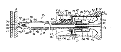
Fig. 1 is a broken side view, partly in section, of an
automatic retractable safety trocar with safety shield
instrument according to the present invention prior to
penetrating a wall, such as a perietal wall, of an
anatomical cavity.
Fig. 2 is a side view of the hub of the automatic
retractable safety trocar instrument of Fig. 1.
Fig. 3 is a broken side view, partly in section, of the
automatic retractable safety trocar instrument of Fig. 1
during penetration of the perietal wall.
Fig. 4 is a broken side view, partly in section, of the
automatic retractable safety trocar instrument of Fig. 1
following penetration of the perietal wall with the safety
shield in an extended position to move a layer of tissue,
such as a visceral wall, away from the parietal wall to
increase the size of the space between the perietal and
visceral walls.
Fig. 5 is a broken side view, partly in section, of the
automatic retractable safety trocar instrument of Fig. 1
following penetration of the perietal wall with the trocar
having been removed from the hub and the safety shield
remaining in place within the anatomical cavity.
- DESCRIPTION OF THE PREFERRED EMBODIMENTS
An automatic retractable safety trocar instrument 10
according to the present invention is illustrated in Fig. 1
and includes an elongate penetrating member such as trocar
WO 93/20866 PCT/US93/03377
.. -. ~ 10
12, a portal sleeve 14 concentrically disposed around trocar
12, a safety shield 16 concentrically disposed between
trocar 12 and portal sleeve 14, a hub 18 mounting trocar 12
and safety shield 16 and a valve housing 20 mounting portal
sleeve 14. The hub 18 can be latched to housing 20 With the
use of any suitable releasable mechanism, such as detents 22
operated by buttons 24, allowing the hub to be removed from
the housing withdrawing the trocar and safety shield from
the portal sleeve. Accordingly, the automatic retractable
safety trocar instrument 10 can be considered to be formed
of a portal unit and a penetrating unit, the portal unit
including portal sleeve 14 and housing 20 and the
penetrating unit including trocar 12, safety shield 16 and
hub 18.
Trocar 12 is preferably made of a medical grade
material, such as stainless steel, and has an outer diameter
or size dependent upon the surgical procedure to be
performed and the anatomical cavity to be penetrated. The
trocar 12 has a distal end 26 terminating at a sharp tip 28
for penetrating anatomical tissue. The distal end 26 can
have various configurations including the various distal end
configurations shown in applicant's co-pending patent
application SN 07/817,113, filed January 6, 1992, the
specification of which is incorporated herein by reference.
As shown in Fig. 1, the distal end has a conical shape
terminating distally at sharp tip 28 and proximally at a
peripheral junction at cylindrical neck 30 which, in turn,
terminates proximally at a frusto-conical shoulder 32. A
helical thread 34 extends along the conical distal end from
the peripheral junction at neck 30 to the tip 28. Shoulder
32 terminates proximally at a diametrically larger
peripheral junction 36 joining the shoulder to an elongated
body 38 which can be cylindrical or have any desirable
configuration in cross-section. Body 38 extends proximally .
from the distal end junction 36 to terminate at a retraction
plate 40 at a proximal end of the trocar, the proximal end
being disposed in hub 18 with body 38 passing through an
11
aperture in a front wall of the hub . The body 3 8 can be
hollow or tubular along the length of the trocar, and an
aperture (not shown) can be disposed at the distal end 26 to
allow communication entirely through the instrument 10 where
a valve is carried on a rear wall of hub 18 has set forth in
applicant's U.S. Patent No. 5,324,268, issued June 28, 1994,
or the body can be partly hollow or tubular to receive a
tube 42 extending distally from the rear wall of the hub and
into the hollow proximal end of the trocar. A retracting
mechanism engages the proximal end of the trocar 12 and
includes the retraction plate 40, an annular rim 44 formed
on tube 42 to be disposed within the proximal end of the
trocar with tube 42 extending through an opening in plate 40
and a coiled helical retracting spring 46 disposed around
tube 42 and mounted in compression between rim 44 and plate
40 to bias the trocar 12 in a proximal direction. To
simplify assembly of the automatic retractable safety trocar
instrument 10, plate 40 can be removably attached to the
cylindrical body 38 such as by threads and the like. The
distal end of the trocar 12 can be removably mounted on the
cylindrical body 38 allowing the various distal tips to be
interchangeably mounted on the cylindrical body of trocar.
A locking and releasing or trigger mechanism 50 is
disposed in hub 18 to actuate the retracting mechanism and
includes a latch or locking spring having a substantially
flat base 52 secured to a wall of hub 18 with an arm 54 bent
inwardly therefrom and extending angularly distally in the
direction of a longitudinal axis of the automatic
retractable safety trocar instrument 10. Arm 54 includes a
section 55 extending parallel with the longitudinal axis,
and a bent locking finger or member 56 is joined to a distal
end of section 55 by a shoulder 58, the shoulder 58 engaging
the retraction plate 40 to prevent movement of the
retraction mechanism and, therefore, the trocar, in a
proximal direction when the locking spring is in its normal
A
WO 93/20866 PCT/US93/03377
~... 12 ~ ~. .
position as illustrated in Fig. 1. The finger 56 extends
distally of shoulder 58, and the trigger mechanism 50 has a
releasing or trigger member 60 disposed along finger 56
distally or forwardly of the shoulder 58. The trigger .
member 60 extends rearwardly or proximally from finger 56 at
an angle to allow movement of an operating member or flange .
thereby in a proximal direction without causing bending of
arm 54 as will be explained further below. The shoulder 58
acts as a positive stop or abutment member to limit proximal
movement of the operating flange by abutment with plate 40,
and trigger 60 is positioned distally of shoulder 58 by a
distance corresponding to the distal movement desired of the
flange or operating member prior to automatic retraction, as
will be explained in more detail hereinafter. The locking
and releasing or trigger mechanism can be mounted at any
suitable location on the hub and provided with any required
configuration to act as a stop or abutment to prevent
proximal movement of the trocar and to be actuated or
released by a distally moving operating member including the
configurations and arrangements set forth in applicant's co-
pending patent applications SN 07/808,325, SN 07/800,507, SN
07/805,506, SN 07/808,325 and SN 07/848,838 referenced above
and the specifications of which are incorporated herein by
reference. The locking and releasing mechanism can be made
as one piece or multiple pieces dependent upon the hub
construction and the operating member utilized to actuate
the trigger. As shown, locking member 56 and trigger 60 are
unitarily, integrally formed of a single strip of resilient,
spring material such as metal or plastic. The locking and
releasing or trigger mechanism can include one or more
locking springs; and, as shown in Fig. 1, a pair of locking
springs are disposed in hub 18 at diametrically opposed
locations along plate 40.
Safety shield 16 is preferably made from a cylindrical _
length of a rigid or flexible medical grade material, such
as stainless steel or plastic, dependent upon use of the
automatic retractable safety trocar instrument, and has a
WO 93/20866 ~ PCT/US93/03377
13
blunt distal end 62 with a configuration to extend beyond
and protect sharp tip 28 of trocar 12 in an extended
position. The safety shield has a cylindrical tubular body
64 extending along the cylindrical body 38 of the trocar 12
and through the opening in the front wall of hub 18.
Tubular body 64 terminates at an operating member or flange
66 at a proximal end of the safety shield, the operating
flange 66 being disposed distally of the retraction plate
40. The distal end of the safety shield 16 is configured to
mate with the distal end of the trocar 12 in a retracted
position for the safety shield and includes a tapering
conical wall distally joined to tubular body 64 and having
an angular inner surface segment 70 distally joined to an
inner surface of the tubular body 64 and a cylindrical inner
surface segment 72 extending distally from the angular inner
surface segment to a blunt distal peripheral edge 74. The
angular inner surface segment 70 is disposed at the same
angle relative to a longitudinal axis of the trocar as the
angle of shoulder 32 relative to the trocar longitudinal
axis, and the cylindrical inner surface segment 72 has an
axial length substantially equal to the axial length of
trocar neck 30. The peripheral distal edge 74 of the safety
shield is shown as being circular, which is preferred if the
trocar tip is conical rather than faceted; however, distal
edge 74 can be scalloped or formed of curved segments 156,
as well as various other configurations including the
configurations shown in applicant's copending patent
application SN 07/817,113, filed January 6, 1992, the
specification of which is incorporated herein by reference.
One or more apertures 75 can be provided in the safety
shield distal end providing fluid communication with an
anatomical cavity through the lumen of the safety shield
when the trocar is withdrawn from hub 18. As shown in Fig.
3, when the safety shield is in a retracted position, the
angular inner surface segment 70 is in contact with shoulder
32 along the length thereof while cylindrical inner surface
segment 72 is in contact with neck 30. Accordingly, the
WO 93/20866 PCT/US93/03377
14
distal end of the automatic retractable safety trocar
instrument has a smooth profile presenting minimal
resistance to tissue as a cavity wall is penetrated. A
coiled helical operating spring 76 is disposed
concentrically around the tubular body 64 of the safety
shield and is connected between operating flange 66 and the
front wall of hub 18, the operating spring 76 being mounted
in tension to bias the safety shield in a distal direction
to an extended position as shown in Fig. 1 with the distal
end of the safety shield protruding beyond the portal sleeve
14.
Hub 18 can be made of any suitable material to be
disposable or reusable and has an external configuration to
cooperate with housing 20 to be easily grasped with one hand
for use in penetrating tissue. Hub 18 can have any desired
configuration in cross-section and is shown in Fig. 1 as
being substantially rectangular while having a flared
profile adjacent the rear wall thereof. As shown in Fig. 2,
a side wall 78 of the hub has a central recessed channel 80
aligned with a' longitudinal axis of the automatic
retractable safety trocar instrument, and a slot 82 is
disposed in the channel 80 and is formed of a longitudinal
portion 84 aligned with the longitudinal axis of the
instrument 10, a distal transverse portion 86 and a proximal
transverse portion 88. A pin (not shown) is threadedly
secured along the periphery of plate 40 and extends through
slot 82, the pin having a "T" configuration to terminate at
an external knob 92. As previously noted, a valve of any
conventional design can be provided in the rear wall of the
hub in alignment with the lumen of tube 42 to allow passage
of fluid entirely through the instrument for additional
confirmation of cavity penetration via leakage detection and
for irrigation and aspiration when the trocar is hollow
along its length or provided with an aperture at the distal _
end to establish fluid communication through the instrument.
A plug or insert 94 is removably mounted by any suitable
means, such as by threads or the like, in the rear wall of
WO 93/Z0866 PCT/US93/03377
15 f
the hub 18 such that the tube 42 and, therefore, the trocar
12, can be withdrawn from the hub 18. Where the plate 40 is
formed separately from the body 38, the plate can be removed
from the trocar allowing the tube 42 to be withdrawn
therefrom such that the insert 94 and the tube can be
replaced in hub 18. The tube 42 can be removably coupled
with the insert 94 allowing the insert alone to be replaced
within the rear wall of the hub. Where a valve is provided
in the rear wall of the hub 18, the valve can be provided in
the insert 94 in communication with the lumen of the safety
shield permitting various medical procedures to be conducted
through the lumen with the trocar withdrawn from the hub and
the safety shield remaining within the anatomical cavity.
Portal sleeve 14 is preferably made of a substantially
cylindrical length of rigid or flexible material, such as
stainless steel or other suitable, medically acceptable,
plastic or metal material, and can be transparent or opaque.
The portal sleeve has a distal end 96 having a configuration
to produce a smooth profile with the safety shield 16 when
the instrument 10 is in an operating state to penetrate
tissue, as shown in Fig. 3, and the portal sleeve has a
proximal end mounted in or formed with a front wall of valve
housing 20 with a lumen extending between the distal and
proximal ends. Housing 20 can be made of any suitable
material to be disposable or reusable and has a
configuration in cross-section corresponding to the cross-
sectional configuration of hub 18 with a flared external
profile adjacent the front wall of the housing facilitating
grasping during use. A wall 98 extends inwardly from
housing 20 at a rear end thereof at a position distally
spaced from the rear end of the housing to produce a recess
for receiving detents 22, the wall 98 having a central
passage for receiving a valve assembly 100. Valve assembly
100 can have any conventional configuration to produce a
closed or sealed condition upon removal of the penetrating
unit from the portal unit. As shown in Fig. 1, valve
assembly 100 is formed of a unitary, one-piece integral
WO 93/20866 _ PCT/US93/03377
16
construction of rubber or soft plastic to facilitate sealing
to prevent fluid flow through the instrument when the
penetrating unit is removed. The valve assembly 100 is
formed of a body I02 having a passage 104 therethrough and
a proximal flange 106 extending outwardly therefrom to be
received in the recess at the rear end of the housing 20.
The body 102 has a peripheral configuration to fit snugly
within the passage through wall 98, and a valve member 108
extends distally from body 102 and has a normally sealed
position with a hemispherical bulging end 110 received in
the valve seat formed at the end of passage 104 to produce
a normally closed, sealed configuration. To provide
assisted bias toward the sealed configuration, a spring
member can be embedded within the valve assembly 100 to bias
the valve member 108 toward the valve seat. While the face
of the valve seat is illustrated as being transverse to the
longitudinal axis of the automatic retractable safety trocar
instrument 10, the valve seat can be angularly oriented as
set forth in applicant's co-pending patent application SN
07/848,838, filed March 10, 1992, the specification of which
is incorporated herein by reference.
In use, the automatic retractable safety trocar
instrument 10 is normally provided in a rest state wherein
the distal end 26 of trocar 12 is retracted within portal
sleeve 14 to be in a safe protected condition, the rest
state coinciding with the retracted position for the trocar
shown in Fig. 4. In the rest state, retracting spring 46 is
in a relaxed, unbiased or unloaded state, with plate 40
abutting the insert 94 or rear wall of the hub 18 carrying
with it trocar 12. Operating spring 76 is similarly in an
unbiased state in the rest position. Accordingly, with the
automatic retractable safety trocar instrument initially .
provided in a rest state, no loading of the springs 46 and
76 exist such that the strength of the springs is not
weakened and shelf life is increased. With the automatic
retractable safety trocar instrument in the rest state, knob
92 will be disposed at a proximal end of the longitudinal
WO 93/Z0866 f PCT/US93/03377
17
slot portion 84 and can be rotated to be received in
proximal transverse slot portion 88 to be locked in that
position to assure that the sharp distal end 28 of the
trocar remains in a protected position. By forming plate 40
separate from the trocar and rotatably mounting the plate 40
on the proximal end of the trocar, knob 92 can be rotated in
slot 88 without rotation of the trocar. In the rest state,
the safety shield 16 will be in an extended position with
the distal end 62 of the safety shield protruding beyond the
distal end 96 of the portal sleeve. When it is desired to
utilize the instrument 10 to penetrate tissue to introduce
the portal sleeve into an anatomical cavity, the knob 92 is
grasped and moved distally within longitudinal slot portion
84 to the distal end thereof causing retraction plate 40 to
move over arm 54 and to be locked in place adjacent the
shoulders 58 as shown in Fig. 1. Locking of the retraction
plate can be confirmed by feel and sound as the locking
member snaps into place and also visually by viewing the
position of knob 92 relative to slot 82. Additionally, the
tube 42 can be made a first predetermined color and the
proximal end of the trocar can be made a second, different
predetermined color with a portion of the hub 18 along the
slot 82 or overlying the tube 42 being made transparent.
Accordingly, the color of the trocar proximal end will be
observed along the slot when the trocar is in the retracted
position of Fig. 4, and the color of the tube will be seen
along the slot when the trocar is in the operative position
of Fig. 1 providing further visual confirmation of locking
of the retraction plate. With the instrument 10 in the
extended or operative condition shown in Fig. 1, the distal
end junction 36 of the trocar will be substantially aligned
with the distal end 96 of the portal sleeve. The safety
shield will remain in an extended position with the
peripheral edge 74 of the safety shield protruding beyond
the distal end 96 of the portal sleeve a distance
corresponding to the size of a potential space to be created
within an anatomical cavity upon introduction of the portal
WO 93/20866 PCT/US93/03377
r.. ....
i~
18
sleeve therein, and the safety shield protrudes beyond the
sharp tip of the trocar to protect the sharp tip.
The instrument can now be utilized to penetrate tissue
and enter an anatomical cavity in two manners. In a first
manner, knob 92 is rotated into distal transverse slot
portion 86 which allows the instrument to be used as a
standard safety trocar with the trocar being prevented from
retracting and the safety shield being movable from the
extended position to a retracted position wherein the distal
edge 74 of the safety shield is substantially aligned with
the junction of the trocar at neck 30 via movement of the
safety shield against the bias of spring 76 due to a
proximal force from tissue contact at the distal end of the
safety shield during penetration of tissue. Accordingly,
upon penetration of a wall of an anatomical cavity, the
distal end of the safety shield will automatically return to
the extended position due to the distal bias while the
trocar is prevented from retracting. In a second manner,
the hub and housing are grasped by the surgeon and the
instrument is forced against tissue T, such as tissue
forming a wall of a body cavity such as a perietal wall, as
shown in Fig. 1, causing safety shield 16 to move proximally
against the bias of operating spring 76 until operating
flange 66 abuts plate 40 and the distal peripheral edge 74
of the safety shield is substantially aligned with the
junction of the trocar at neck 30 as shown in Fig. 3. When
the flange or operating member 66 moves proximally, the
operating member causes trigger members 60 to deflect
proximally such that the flange 66 moves proximally past the
trigger members. The trigger members 60 can be positioned
at varying distances from the operating flange 66 to control
the amount of distal movement of the operating member
required before the trocar is retracted. With the safety
shield in the retracted position, the angular inner surface
segment 70 will be disposed along the conical shoulder 32 of
the trocar and the cylindrical inner surface segment 72 will
be disposed along the trocar neck 30 to present a
WO 93/20866 PCT/US93/03377
19
substantially smooth profile with the distal end of the
trocar and the portal sleeve as shown in Fig. 3. The
instrument is forced through the tissue T to enter the
anatomical cavity with the sharp distal tip 28 of the trocar
extending beyond the distal end of the portal sleeve and the
safety shield and, where the helical thread 34 is provided,
a slow rotational motion can be used during penetration of
the cavity wall to ensure safe introduction of the portal
sleeve in even the narrowest of cavities. Once the distal
end of the instrument has passed through the tissue T,
operating spring 76 will move safety shield 16 distally
causing distal movement of operating flange 66 to engage
trigger members 60 and flex arms 54 in a direction outwardly
from the longitudinal axis of the instrument such that
shoulders 58 are moved out of abutment with retraction plate
40. Accordingly, retracting spring 46 will automatically
move the retraction plate and the trocar to the retracted
position shown in Fig. 4 with the sharp distal tip 28 of the
trocar disposed within the portal sleeve in a safe protected
position. The operating spring 76 will bias the safety
shield 16 to the extended position allowing the blunt distal
end 74 of the safety shield to contact a layer of tissue L,
such as a visceral wall, within the anatomical cavity thusly
creating or enlarging a space between the layer L and the
cavity wall. In the extended position, the safety shield
will protrude from the distal end of the portal sleeve a
distance substantially equal to the distance that the distal
end of the safety shield protrudes beyond the cavity wall
and this distance corresponds to the size of the gap or
space created and maintained between the tissue layer and
the cavity wall via extension of the safety shield as shown
in Fig. 4. The distal end of the safety shield is disposed
further from the cavity wall than the tissue layer when the
safety shield is in the extended position within the cavity
such that the safety shield causes the tissue to move or
bulge in a direction outwardly from the cavity wall to
WO 93/2086', '~~~~ PCT/US93/03377
create, enlarge or maintain a space between the tissue and
the cavity wall.
Once the distal end of the instrument has entered into
the anatomical cavity and the trocar has moved to the
retracted position, the portal sleeve will have been
introduced into the cavity such that the trocar can be
withdrawn from the hub 18 via removal of insert 94 allowing
the safety shield to remain in place in the anatomical
cavity in an extended position as shown in Fig. 5. The tube
42 can be removed from the insert 94 and the insert replaced
on the rear wall of the hub creating a sealed environment
therein or the tube 42 can be withdrawn from the trocar
permitting the tube and the insert to be replaced in the
hub. Where a valve is provided in the insert 94, the lumen
of the safety shield communicating with the anatomical
cavity can be utilized to aspirate fluid from the cavity or
to introduce fluid to the cavity via the apertures 75. A
valve can be provided along the insert 94 or at various
other locations along the instrument to communicate with the
lumen of the safety shield upon withdrawal of the trocar
therefrom. Additionally, the penetrating unit can be
withdrawn from the portal unit leaving the portal sleeve in
place within the cavity and; when the penetrating unit is
withdrawn, the valve member 108 will engage the valve seat
or passage 104 to seal the portal unit from fluid flow
therethrough from insufflation pressure. The one-piece
construction of valve assembly 100 has the advantages of
being inexpensive to manufacture by molding and as being
easily replaceable when used with reusable portal units.
Additionally, the axial length of passage 104 produces an
elongate seal with the safety shield 16 minimizing escape of
fluid during cavity penetration; and, if an instrument of a
different size than the safety shield is to be introduced
after withdrawal of the penetrating unit, the valve assembly
can be easily interchanged to install a valve assembly
having a passage 104 of a diameter to seal along the
different sized instrument. Confirmation of penetration
WO 93/20866 PCT/US93/03377
21
into the anatomical cavity can be sensed or detected
visually from movement of knob 92 along the slot 82 in that
the knob will move to the proximal end of the slot with
retraction of the trocar, tactilely from feel from the
surgeon's hand when the trocar suddenly retracts, and
aurally from the sound of the trocar retracting upon
penetration. Where the tube and the proximal end of the
trocar are different colors and a portion of the hub is
transparent, confirmation of penetration can be detected
visually via an observable color change as the proximal end
of the trocar covers the tube.
Various other structural configurations and
arrangements for the retracting spring, the retraction
mechanism, the operating spring, the operating member, the
locking and releasing or trigger mechanism, the trocar, the
safety shield, the valve assembly, the hub and the housing
can be employed in addition to those shown herein by way of
example, including the various other configurations and
arrangements disclosed in applicant's copending patent
applications SN 07/808,325, SN 07/800,507, SN 07/805,506, SN
07/808,3Z5, SN 07/8I7,113, SN 07/848,838, the specifications
of which are incorporated herein by reference. The
automatic retractable safety trocar instrument 10 can be
modified such that both the trocar and the safety shield
retract within the portal sleeve upon penetration of a
cavity wall, and applicant's copending patent application SN
07/808,325, filed December 16, 1991, and incorporated hereby
by reference, illustrates various configurations and
arrangements of safety shields retractable with a trocar
within a portal sleeve upon penetration of cavity walls.
Automatic retractable safety trocar instruments
according to the present invention can incorporate the
various features and modifications disclosed herein and in
applicant's above-referenced copending patent applications
incorporated herein by reference. For example, the trocar
can have distal ends of various configurations, such as
pyramidal, conical, threaded and multi-faceted, the
WO 93/20866 ~- PCT/US93/03377
F
22
positions of the retracting and operating springs can be
coaxial, concentric, laterally offset, within the trocar or
external of the trocar. Where the springs are laterally
offset, the hub can have a reduced length; and, where the
springs are aligned with the longitudinal axis of the
instrument, the hub can have a reduced width. When the
springs are concentrically disposed and positioned within
the trocar, the overall size of the hub can be minimized.
The springs can be loaded or biased in either tension or
compression; and, preferably, the instruments are provided
for use with both the retracting spring and the operating
spring in a relaxed or unloaded state to increase shelf
life. The pin and slot arrangement between the trocar and
- the hub provides the surgeon with control over the
instrument to allow use without retraction and to allow
manual movement of the trocar to an operative position with
the distal end of the trocar extending from the distal end
of the portal sleeve and in alignment therewith to have the
function and appearance of a standard safety trocar
penetrating instrument. By disposing the knob 92 in a
recessed channel, accidental dislodging of the pin in the
slot 82 is prevented. Movement of the pin also produces a
visual indication of retracting and extending operation of
the instrument which can also be determined by feel and
sound both upon movement of the trocar to the extended
position and to the retracted position as well as visually
by a color change seen along the slot via a transparent or
visible portion of the hub where the tube and the proximal
end of the trocar are of different colors.
The hub arrangement used in the automatic retractable
safety trocar instruments will depend upon procedural
requirements and the springs and locking and releasing ,
mechanisms housed therein. A valve can be provided along
the rear wall of the hub and, in particular, in the insert
94, allowing fluid communication through the trocar where
the trocar is hollow or through the safety shield where the
trocar is withdrawn from the hub.
WO 93/20866 PCT/US93/03377
23
The locking and releasing mechanism chosen for the
automatic retractable safety trocar instruments will depend
upon ease of manufacture and assembly, holding or locking
forces required and releasing forces required. The spacing
of the trigger from the operating member during tissue
penetration will determine the distal movement required of
the operating member prior to automatic retraction of the
trocar. Accordingly, the distance that the safety shield is
allowed to protrude beyond the portal sleeve prior to
retraction of the trocar, and of the safety shield where the
safety shield also retracts, can be controlled such that the
safety shield can push tissue away from the cavity wall
prior to retraction, and the distance can be less than full
extension of the safety shield. The configuration of the
trigger will depend on the bias force on the operating
member and the amount of movement required of the locking
member to release the retraction member. The use of one
piece, metal or plastic strips or leaf springs to form the
locking and releasing mechanisms facilitates assembly while
assembly of multi-part locking and releasing mechanisms can
be facilitated by use of a case to produce a module for
installation in a hub.
The distance that the distal end of the safety shield
protrudes beyond the distal end of the trocar upon
penetration can be selected in accordance with the surgical
procedure to be performed and the cavity to be penetrated
with the distance being selected to correspond to a
potential space to be created within the body cavity upon
introduction of the portal sleeve therein. The distal end
of the safety shield can be formed with various
configurations to safely contact and move an adjacent tissue
layer away from the cavity wall upon penetration therein
with the automatic retractable safety trocar instrument.
With the safety shields in the extended position upon
penetration of the retractable safety penetrating trocar
instruments into body cavities and the trocars retracted
within the instruments, redundant protection and safety is
WO 93/20866 PCT/US93/03377
24
provided to avoid damage to tissue and organ structures
within the cavity.
Insofar as the present invention is subject to many
variations, modifications and changes in detail, it is
intended that a11 subject matter discussed above or shown in
the accompanying drawings be interpreted as illustrative
only and not be taken in a limiting sense.