Note: Descriptions are shown in the official language in which they were submitted.
2118307
WO 94/19535 PCT/F193/00057
Method and device f or ensuring the run of the web in the
multi-cylinder dryer of a plrPrr~-rhin~
The present invention relates to a nethod f or ensuring the
5 run of the web in the multi-cylinder dryer of a p;~r~-rr-rhinP,
as set forth in the preamble of claim 1. The invention relates
aIso to a devlce for carrying out the above method, as set
forth in the preamble of claim 7.
10 The multi-cylinder dryers of a pap~rr--hin~ have employed a
so-called twin-wire run at the downstream end of a drying
section. In the twin-wire run, the wire is supported against
the jackets of cylinders included in two tiers of cylinders
by means of two wires, one running along a tortuous path
15 against the jackets of cylinders of an upper tier and the
other against the jackets of cylinders of a lower tier. When
passing over from one tier of cylinders to the other, the
web travels unsupported. At machine speeds of more than 800
m/min, the air currents produced by the web and moving parts
2 0 of the machine cause f luttering of the web in these open
spaces . The f luttering leads to web breakups at the upstream
end of such cylinder arrays, as the strength characteristics
of the web are still poor due to a high water content.
25 Efforts have been made to resolve this problem by using a
single-wire run, wherein the open runs of a web are eliminated
and the latter travels supported all the time by one and the
same dryer wire between cylinders included in two tiers. The
drying effect of those single-tier cylinders, whereat the
30 wire at this point lies between the web and the cylinder, is
negligible as the wire prevents the transfer of heat from
the cylinder to the web. Indeed, in the most recent r~rh;n~c,
such cylinders have been replaced with suction or vacuum
rolls, and this has resulted in improved machine operating
35 characteristics and the threading ropes have become unnecessa-
ry.
21~07
WO 94/l9s3s PCT/F193/OOOS7
Originally, the single-wire groups generally used to compri6e
just two or three upstream drive groups of a machine, but
their number has been increased as the machine speeds have
increased. Some recent r~rh;n~ lack completely the twin-
5 wire cylinder groups. A drawback in a single-wire run is the
increased length of a dryer section, leading to the increased
leng~h of a machinè hall and~, thus, to7 the- increased ~actory
bll;ld;n~ costs. On the other hand, a drawback affecting the
paper quality is that, in a single-wire run, heat i6 always
10 supplied to the web from the same side of paper, resulting
in possible defects in paper (curling).
As a summary of the above alternatives, it can be said that
the benef its of a twin-wire run include two-sided drying
15 operation and a short dryer section, but the drawbacks include
poorer running characteristics at high machine speeds. The
advantages and disadvantages of a single-wire run are essen-
tially opposite relative to the above.
In addition, e.g. Us Patent 3,753,298 disclosès a machine
configuration, which employs a twin-wire run but in which
the web is all the time supported by either one of the dryer
wires. This is effected by passing the dryer wires by way of
guide rolls mounted between the dryer cylinders in such a
manner that, during the passage between a dryer cylinder and
a guide roll, the dryer wire always runs tangentially to the
other guide roll and the other dryer wire wrapping there-
around, whereby the web can be transferred from one dryer
wire to another at these points without open draws. A weakness
of the solution disclosed in the cited publication is that
the run of a web against a dryer wire between dryer cylin-
ders and wire guide rolls is not secured. Thus, the ~e~,,u
differences prevailing in pockets defined by dryer cylinders
and wire sections, the air currents produced thereby and, on
the other hand, the adhesion forces between the web and
cylinder surfaces detach the web from the dryer wires. Thus,
the open, llr,~ L~ ed web is again susceptible to wrinkling
WO 94119535 2 ~ 1 8 3 ~ 7 PCT/F~s3/00057
.
and, at sufficiently high running speeds, this again leads
to web breakups.
Naturally, attempts have been made to improve the operating
5 characteristics of such a machine conf iguration by providing
such multi-cylinder dryers with air current controlling and/or
producing struct~res at suitable locations. This type of
solutions have been disclosed e. ~ . in Finnish Patents 68279
(Patent Application 841167) and 76142 (Patent Application
8s4494). The passage of the web against the dryer wire is
secured by using vacuum developing blow boxes. However, the
blow box assemblies and nozzle designs ~L~osed in the above
references require very large overall air quantities for a
desired e_fect. These air quantities are typically about
2000-2400 m3/h per pocket. In terms of energy ~ff;r~,Qn~y,
this is undeslred and leads to very large diameters in
comp~nY~ n air manifolds aG well as highly complicated and
expensive air circulation systems.
.
20 An object of the invention is to provide a method and a
device for effecting the above type of closed twin-wire run
with a web supported at all times in a manner that the amount
of air can be min;m; 7ed. In order to achieve this object, a
method of the invention is primarily characterize~ by what
25 is set forth in the characterizing portion of claim 1. An
air guiding surface located on the other side of the dryer
wire and opposite to the pocket allows air to be blown from
said nozzle into said pocket effectively and without large
amounts of air. On the other hand, a device for carrying
30 out the method is characterized by what is set forth in the
characterizing portion of claim ~. Thus, the device includes
a guiding surf ace mounted on t~e other side of the dryer
wire in conjuction with the nozzle and opposite to the pocket
for ~uiding an air current blown from the nozzle through the
3 5 dryer wire and into the pocket .
The annexed dependent claims 2-6 and 8-12 disclose further
preferred embodiments for the method and the device.
21~33û7
WO 94/19535 PCT/F193/00057
The invention will now be described in more det2il with
reference made to the ~ ying drawing, which shows a
side view of a multi-cylinder dryer included in a p;~rPr~^h;nP
and provided with a device for utilizing the invention.
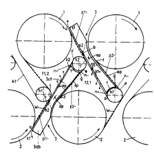
As for its general configuration, a multi-cylinder dryer
shown ïn the dra~ring is~ similarR~ t-~; that~ disclosed in the
above-cited US and FI Patents. The multi-cylinder dryer
comprises cylinders 1 included in a first tier of cylinders
10 and cylinders 2 included in a second tier of cylinders,
these being heated cylinders and intended for removing water
from a web W to be dried, traveling in close conformity
therewith under the guidance of dryer wires . A f irst dryer
wire kl travels in a tortuous path around top cylinders
15 making up the first tier of cylinders, said web W traveling
supported by it and being always pressed against the jacket
of each cylinder 1. Between the cylinders, the wire is passed
around guide rolls hl located below the cylinders, the
position of these rolls being such that the loops formed by
20 the wire and the web pass around the rolls obliquely relative
to the longitudinal direction of said first tier of cylinders.
In a ~uLL~ 7;n~ fashion, said web W is passed around the
jackets of cylinders 2, in this case the bottom cylinders,
included in the second tier of cylinders, by means of a
25 second dryer wire k2, said wire being passed around guide
rolls h2 included in the second tier of cylinders such that
the loops formed by the wire at this point are directed
obliquely relative to the longitudinal direction of said
second tier of cylinders in the same direction as the loops
30 formed by said first dryer wire kl. In order to support web
W over the entire distance, the loops formed by different
dryer wires are arranged to run tangentially to each other
such that over the section, wherein second dryer wire k2
travel6 from cylinder 2 to guide roll h2, it will run tangen-
35 tially to guide roll hl of first dryer wire kl, whereby theweb W extending from the jacket of said cylinder 2 can be
WO 94/1953~ 2 1 1 8 3 Q 7 PCT/FI93/OOOs7
transferred to the loop of wire ki running around guide
roll hl for carrying it further to the jacket of first
- cylinder 1. Since a wire loop located downstream of this
cylinder in the web traveling direction runs in turn tangen-
5 tially to guiae roll h2 of that wire loop from which the web
was transferred, it can be LL~ reLLt:d back again to second
dryer wire k2 for carrying it to a second-t~er cy~ind~er 2.
In order to secure the tran5fer, said wire guide roll5 hl
and h2 are suction rolls.
The first dryer cylinder l, a section of first dryer wire
kl extending from guide roll hl to this cylinder, as well
as a wire section leaving cylinder 1 and located between
the cylinder -and the guide -roll . h2 of - second dryer wire k2
dçfine to~ L with said second .dryer wire k2 a closed
pocket tl,2. A corr~:pnn~l;n~ pocket t2,1 is formed at 5aid
second cylinder 2.
The invention will now be described with reference made to
equipment associated with the loop formed by said second
dryer wire k2 winding on guide roll.h2, but the same applies
analogically also to equipment associated with the loop of
the f irst dryer wire kl . These loops include three sections:
a section a-c, wherein the wire runs along with web W from
the cylinder to the location of wire guide roll, at which
the web is transferred-to the dryer wire passing therearound,
a section c-d, wherein the wire starting from the transfer
point c ~l~yl~s~ie:~ to the wire guide roll, as well as a
section e-f, wherein the wire carrying the web W transferred
3 0 back travels from guide roll to dryer cylinder .
At the loop formed by second dryer wire k2, along a section
a-d between dryer cylinder 2 and guide roll h2, a nozzle 82
is mounted, located on the opposite side of wire k2 relative
to pocket tl,2. The nozzle is intended for blowing air into
pocket tl,2 for its ventilation and for securing the sta~ility
of web W over the sections of f irst dryer wire kl def ining
the pocket, the nozzle having the same basic purpoSe as the
_ _ _ _ _ _ _ _ .
-
~ 0 94/l9535 2 1 1 8 3 0 7 PC~93l00057
nozzles disclosed in the above-cited Finnish Patents 68279
and 76142. Downstream in the traveling direction of dryer
wire k2 said nozzle s2 is followed by an air guiding surface
op, facing a wire section c-d. The air blown from nozzle s2
5 is guided along this section into a space between wire k2
and surface op, which space will thus be ~ v~ ,,usized
and this plenum zone is indicated wi~h reference ch~racter
pl+. The air guiding surface, which extends roughly parallel
to section c-d, covers most of the length of this section,
10 preferably extending to the proximity of the jacket of wire
guide roll h2. In the drawing, the surface extends all the
way to the gap between the wire and the roll, i.e. it extends
beyond a plane tangential to the roll jacket and perpendicu-
lar to wire k2.~ Thus, ~the :gap n+ between- dryer wire k2 and
15 ro~ll h2 located upstream~of point d will-also be over-pressu-
rized. In view of int~nc;fying the gap over-~l~s,.-L_, a
sealing t is f itted between the jacket of guide roll h2 and
an arched surface hp facing the roll jacket and adjoining
the end of air guiding surface op and the roll jacket. The
20 blowing air travels from plenum space pl+, n+ limited by
wire k2 into pocket tl, 2 through the air-r~ -hl .~ section
c-d of dryer wire k2 not covered by web W, taking care of
ventilation of the pocket.
25 The nozzle s2 is located in the traveling direction of dryer
wire k2 u~aLr~:cuu of point c, at which said web W is transfer-
red from second dryer wire k2 to first dryer wire kl. The
location, at which the plenum zone between the dryer wire
and the guiding surface therefore begins, is indicated with
3~ reference character b and it is located upstream of point c.
In the dryer wire traveling direction, u~ U of point a,
at which the dryer wire departs from cylinder 2, a nozzle 61
i9 located for producing an air flow directed against the
wire traveling direction. Thus, between nozzles sl and s2
3 5 within the section a-b there is provided a vacuum zone pl- .
The development of this vacuum is assisted by a surface ap,
located between nozzles sl and s2 and facing section a-b
The vacuum zone can be used for sucking web W into the contact
_ _ _ _ ., _ _ _ _ _ _ _ _ _ . . . ... _ _
WO 94119535 2 1 ~ 8 ~ 0 7 PcT/E~931ooo57
.
with dryer wire k2 over section a-b. Since the vacuum zone
terminates u~al Le~L~I of point c, the transfer of web W from
one wire to another is facilitated.
5 The nozzle s2 directed in the traveling direction of second
dr~rer wire k2 has two functions, namely serving as an ejector
nozzle Lor producing a vacuum w~thin a zone limited directly
by section a-b of the wire as well as an ~v~ S:,ule within
section c-d and P~pP~ l y in gap n+ between dryer wire k2
lO and guide roll h2, for taking care of pocket ventilation as
the blowing air finds its way into pocket tlr2.
In practice, the nozzles sl and s2, vacuum surface ap, and
air guiding sUrface op can be simply formed such that said
15 surfaces ap and op are provided by the dryer wire X2 facing
side of a common air-blowing box 3 located inside the wire
loop, whereby nozzle s2 opens on said side between surfaces
ap and op and nozzle sl is located at the end of the box
upstream of point a, at which the wire and the web depart
20 from dryer cylinder 2.
Within the section e-f, wherein the dryer wire k2 progresses
from guide roll h2 to cylinder 2 together with web W received
thereon at guide roll h2, there is in turn created another
25 vacuum zone p2- on the other side of the dryer wire relative
to pocket t2, l . This - vacuum zone is produced by arranging an
ejector surface ep inside the dryer wire loop opposite to
the wire. Between the ejector surface and the wire within
this zone there is induced a vacuum, since the wire has a
3 o tenaency of grabbing air therealong when traveling at a high
speed. In order to intensify the vacuum, said ejector surface
ep ~orms an angle with the wire which can be in the order o~
0-~ o, opening slightly in the wire traveling direction. The
vacuum zone extends in the direction opposite to the wire
3~ traveling direction all the way to gap n- between the jacket
of guide roll h2 and the wire section e-f In order to
intensify the gap vacuum, the ejector surface ep extends in
this direction all the way to the gap, i. e. beyond a plane
A
WO 94119535 ~ 2 1 1 8 3 ~ 7 PCT~3~aOOST
.
tangential to the jacket of guide roll h2 and perpendicular
to wire k2, wherein it is joined at point g by the arched
surface hp following the jacket of roll h2 As shown in the
drawing, the ejector surface ep is constituted of the wire
5 section e-f facing side of the same air-blowing box, which
also i nr~ c vacuum surface ap and air guiding surface op.
The arched wall, c~nno~;n~ air guiding surface op and ejector
surface ep and facing the jacket of guide roll h2, is provided
with the abv~ ioned sealing t which, at the same time,
lO separates gaps n+ and n- as well as the respective plenum
and vacuum zones from each other.
Thus, a single air-blowing box located inside the dryer wire
l-oop, by means of a proper design of its sides~ can be used
15 for producing both the vacuum zone pl- for securing the
adherence of web W to the wire over section a-b, the plenum
zone pl+, n+ taking care of the ventilation of pocket tl,2,
as well as the vacuum zone p2-, n- for securing the adheren-
ce of web W to dryer wire k2 or kl upon its transfer from
20 the zone of action of the suction-equipped guide roll h2 or
hl at point e to be supported by said wire k2 or kl within
section e-f. In addition, it should be appreciated that the
plenum zone pl+, n+ for providing the ventilation of pocket
tl, 2 or t2, l also improves the adherence of web W to the
25 dryer wire within sections which define the co- L. ~ ;n~
pocket and are located immediately upstream and downstream
of dryer cylinder l or 2.
The edges of vacuum zones pl- and pZ- can be provided with
30 known edge blowers for preventing the flow o~ leakage air from
the surroundings at the wire edges into the vacuum zone
The air-blowing box 3 conceivably comprises an air-blowing
35 part 3ab, which receives blow ducts and is provided with
nozzles sl and s2, as well as an alr guiding part 3cf mounted
thereon and including air guiding surfaces op and an ejector
surface ep as well as surface hp connecting them. Due to the
' WO 94119535 2 1 1 8 3 o 7 PCT/FJ93/00057
9
configuration of a pap~ k;n~ machine these parts can
sometimes be mutually separate parts, which, when positioned
successively, provide the above assembly inside the wire
loop .
s
Fur~h- ~, the drawing illustrates how to arrange a flow
regulator between the blowing part and the air guiding part,
- such as a damper plate sp, capable of regulating the amount
of air flowing from nozzle 52 through dryer wire k2 into
10 pocket tl,2. The damper plate is located in a flow duct
that connects the surface downstream of nozzle s2 with ambient
air. When the damper plate is open, some of the air entering
in the air-blowing part is allowed to f low out . When the
damper plate is closed, all the air flows from the nozzles
15 which are in communication with the air-blowing part. In
cross-wire direction, the box can be further provided with a
plurality of damper plates that can ~e adjusted for affecting
the distribution of air in lateral direction.
A