Note: Descriptions are shown in the official language in which they were submitted.
- 1 -
ORTHOGONAL POLARIZATION AND TIME VARYING OFFSETTING
OF SIGNALS FOR DIGITAL DATA TRANSMISSION OR RECEPTION
Field of the Invention
The present invention relates to the field of wireless
data transmission and reception. More particularly it
relates to inducing rapid fading characteristics and
improving reception.
Background of the Invention
In wireless communication systems, such as digital
radio or television transmission, an information signal is
communicated from a transmitter to a receiver as multiple
signals via a channel comprising several independent paths:
These multiple signals are called multipath signals and the
channel is called a multipath channel. Because of the
complex addition of multipath signals, the overall signal
strength at a receiver will vary. The phenomenon of
received signal strength variation due to complex addition
of multipath signals is known as "fading".
A channel encoder (also known as a "channel coder") or
similar device can be employed to compensate for fast
fading. If the signal strength at a receiver "fades"
slowly, however, a receiver experiencing a low signal
strength, called a "deep fade", will observe a weak signal
strength for a longer period of time than can be readily
compensated for using a channel coder. Slow fading is a
particular problem in car radio receivers.
Two types of channel coding systems are block coding
and convolutional coding. Slow fading may cause a burst of
incorrect data symbols at a data receiver. If the burst of
incorrect data symbols is short enough the channel coder can
detect or correct it. However, when fading is too slow,
long bursts of errors can occur which cannot be adequately
corrected and unacceptable performance results.
CA 02118355 1998-O1-12
- 2 -
Interleaving/deinterleaving with a channel coder can be
used to further combat slow fading. An interleaver at the
transmitter rearranges a set of data symbols in a pseudorandom
fashion and a deinterleaver at the receiver rearranges the
symbols in the original order. However, interleaving/-
deinterleaving with a channel coder is not sufficient to combat
fading if the deep fades last for long enough periods of time.
Spatial diversity can also be used to combat slow fading.
Spatial diversity involves the use of a plurality of receiving
and/or transmitting antennas. If two receiving antennas, for
example, are spatially diverse from one another, the two
signals received at the individual antennas will have
independent fading characteristics and can be combined to
reduce the probability of deep fades, independent of the fading
rate.
Unfortunately, spatial diversity may require wide spacing
of receiver antennas, typically at least a quarter wavelength.
Thus, the receiver antennas must be separated by at least 2.5
feet for audio broadcasting at 100 MHz, which is impossible to
achieve in small portable receiving systems.
Spatial diversity may also be achieved using multiple
transmit antennas. However, transmitting the same signal oout
of each transmit antenna is not useful, as it just generates
more multipath signals at the receiver. One technique
previously proposed is to use channel coding with inter-
leaving/deinterleaving in combination with a time varying phase
offset between each antenna as proposed in Canadian Patent No.
2,094,193 issued October 30, 1997 to Weerackody. This time
varying offset creates rapid fading at the receiver antenna,
which can be compensated by channel coding with
interleaving. For this technique to be effective,
however, the signals received from the multiple
- 3 -
transmit antennas must be independent. Unfortunately, in
digital audio broadcasting (DAB) for example, the transmit
antennas are usually very high, e.g., on top of the World
Trade Center, to provide wide area coverage. At such
heights spacing of tens of wavelengths between the transmit
antennas is required to insure substantially independent
fading. At 100 MHz with digital audio broadcasting, the
required spacing is therefore in excess of hundreds of feet,
which is not generally practical.
Summax-Sr of the Invention
The present invention provides a technique for creating
rapid fading at the receiver. In digital broadcasting, such
as digital audio broadcasting, with rapidly varying fading,
channel coding with interleaving is utilized to provide
improved performance at the receiver. This addresses the
problem presented by slow fading, as with a stationary or
slow moving user, experiencing long periods of poor
performance such as are typically observed with a slow fade.
To create rapid fading, even for a slow-moving user, the
signal is transmitted by two orthogonally polarized antennas
with a slight time varying offset between the two antennas.
Since existing broadcast antennas use orthogonally-polarized
antennas, this technique can be easily implemented at the
transmitter to overcome the above problem and provide
satisfactory performance to all users.
As the reflection coefficient for most objects is
polarization dependent, substantially independent fading
from two orthogonally polarized antennas can be obtained.
A time-varying phase offset, for example, between the
antennas creates a time-varying transmit polarization
resulting in time varying fading at the receiver. In one
embodiment, the transmit polarization is continuously varied
from left-hand circular to right-hand circular, two
polarizations which have been shown to have high cross-
~11.8~~5
- 4 -
polarization and low cross-correlation on reflection,
resulting in substantially independent fading between the
signals received at the times of extremes of the transmitted
polarization. As most broadcast antennas use linear arrays
to direct most of the transmitted energy downward and use
two orthogonally-polarized arrays to increase transmitted
power by 3 dB (with equal power to each of the
polarizations), the technique requires only the addition of
a time-varying phase offset, or shift between the
orthogonally-polarized signals of standard antennas.
In another embodiment of the invention, more than two
transmitting antennas are employed. At least one of said
plurality of antennas transmits a signal which .is
substantially orthogonally polarized with respect to a
signal transmitted from at least one other of said plurality
of antennas, and a different time varying offset is applied
to two or more of the plurality of substantially
orthogonally polarized signals to result in fast fading
which may be more readily compensated for.
In another embodiment, fast fading is achieved and slow
fading is substantially eliminated by receiving a
transmitted signal with a plurality of antennas. At least
two of these antennas are arranged with respect to each
other such that they receive substantially orthogonally
polarized signals, and a different time varying offset, such
as a time varying phase offset, is provided to one or more
of the substantially orthogonally polarized received
signals.
The present invention is preferably used in conjunction
with interleaving and deinterleaving and channel coding.
The present invention can also be used with other techniques
such as spatial diversity to further reduce the effects of
fading. ,
Further features of the invention, its nature and
various advantages will be apparent from the drawings and
- 5 -
the following detailed description of the invention.
Brief Description of the Drawings
Fig. 1 illustrates a situation where a deep fade can
occur; Fig. 2 is a graph of signal strength versus
distance which illustrates fading for a single transmitting
antenna and a single receiving antenna;
Fig. 3 shows a basic transmitter section illustrative
of an embodiment of the present invention;
Fig. 4 is a graph of signal strength versus distance
between transmitter and receiver when substantially
orthogonally polarized signals and time varying offsets are
used in accordance with the present invention;
Fig. 5 shows a further transmitter section according to
the present invention;
Fig. 6 shows a receiver section to be used with the
Fig. 5 transmitter section of the present invention;
Fig. 7 shows a spatially diverse transmitter section in
accordance with the present invention; and
Fig. 8 shows a receiver section which includes two
antennas for receiving two substantially orthogonally
polarized signals in accordance with a further embodiment of
the present invention.
Detailed Description of the Invention
Fig. 1 illustrates a situation where deep fading can
occur. In this situation, phasors S1 and SZ represent the
received signals from two transmitting antennas T1 and Tz,
respectively. In this situation, destructive addition of
the phasors S1 and Sz results in a deep fade which can be
compensated by the present invention.
Fig. 2 is a graph of signal strength versus distance
for a single transmitting and a single receiving antenna.
It illustrates fading in a different way than Fig. 1. As
shown in Fig. 2, the received signal strength y varies with
~1~.8~~~
- 6 -
the distance x of the receiver from the transmitter. At a
distance x1, the received signal is below a signal strength
y1, where signal strength y1 is one below which data
reception may be compromised. In the context of a digital
audio broadcast being received by a car radio, if the car is
moving slowly or is stopped at the distance x1 from the
transmitter, the deep fade may be observed for an
unacceptably long time. Such fading may be characterized as
slow fading. The present invention reduces the problems
arising from slow fading by inducing rapid fading which may
be suitably compensated for.
Referring to Fig. 3, a transmitter section 10 according
to the present invention is shown. A receiving antenna.35
is also shown. The transmitter section 10 includes a data
signal source 20, channels 21 and 22, and an oscillator 26,
which applies a time varying phase offset, a mixer 24, and
two transmitting antennas 30 and 32.
The data signal source 20 provides a data signal "D",
such as a digital audio broadcast signal, to the inputs of
both of the channels 21 and 22. The signal D is carried by
the channels 21 and 22 to the antennas 30 and 32,
respectively. The mixer 24 and oscillator 26 time vary the
transmit phase of the signal transmitted from the antenna
30. The rate of variation of the antenna polarization
should be about 1-2~ of the data symbol date. A time
varying phase offset corresponding to a fixed frequency
offset of about 1-2~ of the data symbol rate may be used.
Therefore, a time varying phase offset which results in a
fixed frequency offset of about 3-6 kHz, for audio
broadcasting may be used.
The antennas 30 and 32 are linear antennas which are
configured to transmit substantially orthogonally polarized
signals. Antenna 30 transmits a linearly polarized signal
in the vertical plane, while antenna 32 transmits a linearly
polarized signal in the horizontal plane. The receiving
~11~3~
antenna 35 receives the combined transmitted signals, after
transmission through multiple paths, and after modification
by noise, delay, and distortion.
Fig. 4 graphically illustrates the rapid fading
characteristics created by the present invention. The solid
envelope curve 30' shows the signal strength which might be
observed at a receiver due to the signal transmitted from a
single antenna 30. The dashed envelope curve 32' shows the
signal strength which might be observed due to the signal
transmitted from a single antenna 32. The curve 31 between
the envelopes illustrates the resulting rapid fading signal
which might be received by receiver 35 from transmitter 10
with the substantially orthogonally polarized signals
transmitted from antennas 30 and 32 with time varying offset
applied to the signal transmitted by antenna 30. It should
be recognized that Fig. 4 is illustrative only and that the
rapid fading signal curve 31 may at times exceed the bounds
of the two single antenna signal envelopes 30', 32'.~
Furthermore, the signal strength will vary even at a fixed
distance.
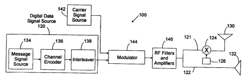
Fig. 5 shows a transmitter 100 according to the present
invention. The transmitter 100 includes a digital signal
source 120, which includes a message signal source 134, a
channel encoder 136, and an interleaver 138. Transmitter
100 further includes a carrier signal source 142, a
modulator 144 with first and second inputs, an RF filter and
amplifier section 146, channel 121 which includes mixer 124
and oscillator 126, channel 122, and orthogonally polarized
transmitting antennas 130 and 132.
Message signal source 134 provides a digital data
signal Dm to the channel encoder 136. Channel encoder 136
applies an error control coding technique to the signal Dm
(or a "channel coding" technique) and outputs a signal De.
The error control coding technique applied by channel
encoder 136 may be block coding or convolutional coding. In
g _
the case of a typical digital audio broadcast system, the
input data rate to the channel encoder is in the range of
about 300 kbits/second. Typically, the interleaver is a
block interleaver and the modulation scheme is 4-PSK.
Additional induced channel variations are introduced by
small carrier frequency offsets using mixer 124 and
oscillator 126. Suppose fl is the carrier frequency
transmitted from antenna 130. Then, fl = f~ + Of. In this
case, f~ is the carrier frequency of the signal transmitted
by antenna 132 and ~f is the frequency offset at
transmitting antenna 130. This fixed frequency offset can
be typically in the range of 1 - 2~ of the data symbol rate.
Smaller frequency offsets will not sufficiently decorrelate
the data symbols at the input to the channel decoder (at the
receiver) . On the other hand, larger frequency offsets will
make the demodulation and the equalization functions
difficult. Alternatively, the frequency offset may be
applied to the baseband data stream before it is sent to the
RF unit and the antenna.
A 200 millisecond delay or duration for interleaving is
an appropriate duration for digital audio broadcasting
applications. The interleaver 138 is provided to rearrange
the data of the signal De in a pseudorandom fashion. The
output of interleaver 138, a signal Di, is provided as an
input to the second input of the modulator 144. A second
signal, carrier signal C, is provided as an input to the
first input of modulator 144. A modulated carrier signal Cm
is produced at the output of the modulator 144.
The modulation technique used is preferably phase shift
keying (PSK), although other modulation techniques such as
amplitude shift keying (ASK) and frequency shift keying
(FSK) can be used with a digital data source. The modulator
can be coherent or employ differential encoding. Coherent
modulation, such as PSK, is preferred because an equalizer
is preferably used in the receiver. However, differential
211~~~~
- 9 -
encoding such as differential phase shift keying can be
used.
The signal Cm is input to the RF filter and amplifier
section 146. In section 146, filters shape the spectrum of
modulated carrier signal Cm and amplifiers increase the
signal strength to an appropriate level for transmission.
A filtered and amplified signal Cf is produced at the output
of the RF filter and amplifier section 146 and applied to
the inputs of the two channels, 121 and 122. The signal Cf
is thus input to both antenna 132 and mixer 124. The
oscillator 126 and mixer 124 apply a time varying phase
offset, Offa(t) to the signal Cf applied to an input of the
mixer 124. The offset signal Ca is the resultant output
signal from the mixer 124. The signals Ca and Cf are applied
for transmission to the antennas 130 and 132, respectively.
In this embodiment, the antennas 130 and 132 are preferably
helical antennas. With this arrangement, the antenna 130
transmits a right hand circularly polarized signal and
antenna 132 transmits a left hand circularly polarized
signal.
Fig. 6 illustrates a receiver section 200 which is
suitable for use with the transmitter 100 of Fig. 5. The
receiver section 200 includes a receiving antenna 235, an RF
filter and amplifier section 202, a demodulator 204, an
equalizer 206, a deinterleaver 208, and a channel decoder
210.
The antenna 235 receives a combined signal consisting
of the addition of the signals Ca and Cf, after their
transmission through various multipaths, and after
modification by noise, delay, and distortion. The received
signal becomes the input of the RF filter and amplifier
section 202. In section 202, RF filters reduce noise and
amplifiers increase the received signal strength. The
output of the RF filter and amplifier section 202 is then
applied to the demodulator 204 which demodulates the signal.
~11~'3~~
- 10 -
The output of demodulator 204 is applied to the equalizer
206 which helps to reduce any amplitude and delay
distortion. Equalizer 206 in Fig. 6 can be a decision-
feedback type. The output of equalizer 206 is applied to
the deinterleaver 208 which is used to rearrange data
symbols to undo the process of interleaving which occurred
in the interleaver 138 in the transmitter 100. The output
of the deinterleaver 208 is applied to a channel decoder 210
which derives the original data message signal, and produces
that signal at its output.
Although a frequency offset has been illustrated in
Fig. 5, time varying amplitude or other time-varying phase
offsets can also be used. The time varying offsets maybe
continuous or may take on discrete values as a function of
time. Time varying offsets can be applied by mechanically
moving one of the antennas or preferably by circuits known
in the art which electronically apply time varying phase or
amplitude offsets to an input signal. For example, an input
signal can be applied to first input of a mixer, such as
mixer 124, whose second input is a low frequency signal from
an oscillator, such as oscillator 126, as shown in Fig. 5.
The low frequency signal applies a time varying phase offset
(which in this case is the same as a fixed frequency offset)
to the input signal. .
The time varying offsets introduced to the transmitting
antenna signals should not be large enough to cause
erroneous data transmission. On the other hand, time
diversity of fading improves with faster offsets at the
transmit antennas. Preferably, the offsets vary at a rate
which is between 1 to 2~ of the data rate, for example, a 3-
6 kHz rate for 300 ksymbols/sec DAB transmission system.
This is small in comparison to the data rate but large
enough to cause sufficient time diversity.
While there are a myriad of polarization schemes which
would be known to those skilled in the art, it is preferred
~i~.8~55
- 11 -
that antennas in accordance with the present invention be
configured to create vertically/horizontally polarized or
left/right hand circularly polarized signals. These
polarizations create signals which have fading that is
highly uncorrelated at the receive antennas.
A carrier signal source in accordance with the present
invention preferably produces a sinusoidal signal and may
operate at a frequency of about 100 MHz for applications
such as FM digital audio broadcasting.
Referring to Fig. 7, a spatially diverse transmitter
300 is shown. The transmitter 300 includes a signal source
302, channels 304, 306, 308, and 310, mixers 312, 314, and
316, transmitting antennas 320, 322, 324, 326, a_nd
oscillators 332, 334, and 336.
A signal S is output from the signal source 302 and is
applied to the inputs of each of the channels 304, 306, 308,
and 310. Each channel but one includes an mixer which has
an input connected to an oscillator. Each oscillator
applies a different time varying phase offset through its
corresponding mixer. Each oscillator frequency is different
and each is independent of the signal from the respective
channel. Offset signals are produced at the outputs of the
mixers 312, 314, and 316, and are applied to the antennas
320, 322, and 324, respectively.
The antennas 320 and 322 are spatially diverse from
each other to further reduce the effects of fading. The
antennas 324 and 326 are similarly spatially diverse.
Antennas 320 and 322 are preferably linear antennas which
transmit signals with vertical polarization. Antennas 324
and 326 are preferably linear antennas which transmit
signals with horizontal polarization.
The signal source 302 may have components corresponding
to the message signal source 134, channel encoder 136,
interleaver 138, carrier signal source 142, modulator 144,
and RF filters and amplifier section 146, shown in Fig. 5.
211.8~~5
- 12 -
Referring to Fig. 8, a receiver 400 according to the
present invention is shown. The receiver 400 includes two
receiving antennas, 424 and 426, mixer 428, an oscillator
432, a signal combiner 434, and a signal processing block
430.
The antennas 424 and 426 are preferably linear
antennas. Antenna 424 transmits with vertical polarization
and antenna 426 transmits with horizontal polarization.
Mixer 428 and oscillator 432 apply a time varying phase
offset to the signal received by the antenna 426. The
signal processing block 430 may include elements
corresponding to the RF filter and amplifier section 202,
demodulator 204, equalizer 206, deinterleaver 208, and
channel decoder 210, shown in Fig. 6.
While the benefits of orthogonal polarization with time
varying offsets are particularly significant in the context
of FM digital audio broadcasting and have been described
above principally in that context, to provide transmit.
diversity of transmitting/receiving antennas in the present
invention is also useful for other wireless transmission
schemes, such as digital HDTV and the like.