Note: Descriptions are shown in the official language in which they were submitted.
26710/RDS
SEAL PROTECTION FOR ROCK BITS
Back~round
This invention relates to rotary cone drill bits and means for preventing drill cuttings
from entering the bearings. More particularly, this invention provides a drilled cuttings
diverter or barrier in conjunction with a circumferential groove on the backface of the bit leg.
It has long been recognized in the drill bit industry that the longevity of sealed bearing
rotary cone drill bits is greatly increased if debris is prevented from entering the bearings
0 associated with each of the rotary cones rotatably retained on the legs of a drill bit. Drill bits
used in carrying out rotary drilling are subject to destruction by erosion caused by the
abrasive effect of the rock detritus entrained in the drilling fluid. Fluid circulation is
employed primarily to circulate or flush the debris or formation cutting~ from the well bore.
In actual practice, mud and solids from the circ~ ting fluid and from the earthen
formations pack onto certain portions of the bit structure. This packed material flows or
extrudes and moves relative to certain portions of the bit. Since great pressures are utilized
in the drilling operations, the movement or flow of this packed material has adverse effects
on the bit structure and, in particular, the seal cavity, the seal and bearings associated with
each rotary cone of the bit.
U.S. Patent No. 2,960,313 addresses the foregoing problem. Means are provided tomechanically deflect mud and cuttings from a path that normally results in wear and
destruction of a roller cone bit. A deflecting post or pin is provided in the leg backface.
The end of the pin is adjacent a cone backface, the pin serving to deflect detritus or debris
as it invades the space between the cone backface and the leg backface. The pin is fixed in
2 5 the leg backface and has an exposed cylindrical end that termin~t~s in a flat surface, the flat
surface paralleling the rotary cone backface.
The deflecting post, while being somewhat effective in intercepting the flow of debris,
has a circular shape that can divert debris and fluid towards the seal cavity, thus allowing
some debris to enter this cavity.
3 0 U.S. Patent No. 3,013,621 describes a means to deflect abrasive particles or cuttings
from the space formed between a leg backface and a conical cutter. An overlay of hardened
materials is welded to the leg backface at an angle to a radial plane from a journal center
line. The abrasion resistant material metallurgically attached to the leg backface serves to
scrape or divert debris away from the cone bearings to prevent the debris from entering and
3 5 destroying the bearing during operation of the bit in a borehole.
This means of diverting the fluid and accllm~ te~l cuttings is somewhat ineffective
because the space between the leg backface and the cutter backface is very restricted.
Therefore, a minim;~l volume of drilling fluid can be circulated between the cone and the leg
backface to flush away the abrasive drill cutting~. This allows intim~te contact of the
4 o abrasive cuttings with the seal gland, promoting premature seal and bearing failure.
U.S. Patent No. 5,056,610, assigned to the same assignee as the present invention,
describes a roller cutter bit having a drill cuttings diverter to prevent packing and abrasion
of the bearing seal gland. This diverter consists of a burn plug positioned in the leg backface
that is energized to force the plug into contact with the roller cone backface to wipe clean
the face proximate the seal gland.
Although this system initially does remove the build-up of detritus at the seal gland
area, the hard metal burn plug wears a cil~;ulllfelelllial groove in the cone backface near the
seal fairly rapidly, exposing the seal to more abrasive cuttings, thereby accelerating seal
wear. A significant amount of heat is generated by the plug wearing a groove in the cone,
0 which at times deteriorates the seal.
The present invention has an advantage over the above prior art mech~nisms in that
the leg backface surface is a recessed circumferential groove instead of a flat surface. A
hard abrasive resistant shale diverter pad is affixed fully across the leg backface groove at
an angle that is approximately tangent to the seal gland outer diameter so that the outer edge
of the pad angles into the direction of the rotation of the cone. The diverter pad wipes the
accumul~ted detritus from the roller cone heel area and the adjacent circumferential groove
in the leg backface allows a significantly more than normal volume of drilling fluid to
continuously flush the seal gland area clean of cutting~ and other detritus.
2 o Summary of the Invention
The foregoing features and advantages are achieved by providing a sealed bearingrotary cone drill bit having a body that has a first pin end and a second cutting end. A
dowllw~ldly extending leg has an outer surface and a journal bearing integrally formed with
the leg and projecting inwardly therefrom. A circumferential groove is formed at the
juncture of the journal bearing and the leg. A cutter is rotatably mounted on the journal
bearing. The cone has a backface that is adjacent to the groove formed on the leg. The
enlarged groove provides enh~n~ed fluid flow that removes detritus from the region of the
sealed bearing.
The leg further has an angled raised pad of hard, abrasion resistant material that
3 0 intersects and closes the circumferential groove at the trailing end relative to bit rotation.
The hard metal pad also ties into hard metal on the outer surface of the shirttail.
A rock bit body has a first pin end and a second cutting end. At least one leg extends
from the body toward the second cutting end of the bit. The leg rotatably supports the rotary
cone from a bearing journal that is cantilevered from the base of the leg. A leg backface is
3 5 formed by a shirttail formed at the base of the leg. The backface is positioned adjacent a
cone backface on the rotatable cone. The leg backface in the shirttail portion forms an
enlarged fluid passageway between the leg and the cone backface adjacent the bearing cavity.
The enlarged passageway provides a means to allow fluid to flush detritus from the bearing
cavity during operation of the rock bit in an earthen formation.
4 o An advantage then of the present invention over the prior art is that the hard metal pad
acts as a barrier and prevents the large particles of formation cuttings from going between
the cone and leg backface and the greater volume of fluid in the groove scavenges the smaller
abrasive particles from the bearing seal interface. Yet another advantage of the present
invention over the prior art is that the larger fluid volume in the groove serves to better cool
the seal and bearing for longer bit life.
Brief Description of the Drawin~s
The above noted objects and advantages of the present invention will be more fully
understood upon a study of the following description in conjunction with the detailed
drawings. FIGURE 1 is a partial cross section of a prior art sealed bearing rock bit roller
0 cone mounted on a journal extending from the bit leg.
FIGURE 2 is a perspective view of sealed bearing roller cone rock bit.
FIGURE 3 is a partially broken away and sectioned view of the lower end of a leg of
a rock bit illustrating a rotary cone mounted on a journal extending from the leg.
FIGURE 4 is section 4-4 of Figure 3 showing the backface of the bit leg.
Description
With reference to the prior art illustrated in Figure 1, a sealed bearing roller cutter
rock bit leg and cone assembly, generally designated as 1, shows a cone 3 rotatably mounted
on a journal 6 cantilevered from a leg 2. The planar surface of the leg backface 5 is opposed
2 o by the planar surface of the cone backface 4. The clearance 7 between these two surfaces
is normally held to fairly close tolerances to help limit the axial movement of the cone on
the journal. This narrow annular space 7 tends to pack with shale cuttings and other debris,
which then encroaches on the seal 8, ultimately destroying it. This allows drilling mud and
abrasive drill cuttings to enter the bearing cavity, thereby destroying the journal bearing and
25 termin~ting the bit run.
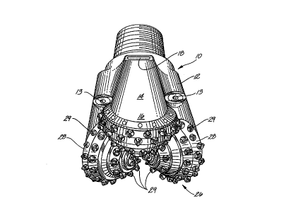
Figure 2 depicts a sealed bearing rotary cone rock bit, generally designated as 10 that
comprises a rock bit body 12, pin end 11 and a cutting end generally designated as 26. Each
cone 28 making up the cutting end 26 is attached to a leg 14. Each leg termin~tes in a
shirttail portion 16. Each of the cones 28 has, for example, a multiplicity of strategically
3 0 spaced tungsten carbide cutter inserts 29 interference fitted within insert holes formed in the
cone bodies 28. A lubricant reservoir, generally designated as 18, is provided in each of the
legs to supply lubricant to bearing surfaces formed between the rotary cones and their
respective journals. Three or more nozzles 13 collu.lul~icate with a chamber (not shown)
formed inside the bit body. The chamber receives drilling fluid or "mud" through the pin
3 5 end 11. The fluid is then directed out through the nozzles during the drilling operation.
Figure 3 illustrates a leg 14 of the rock bit with a cone 28 mounted on a journal 15.
A plurality of cone retention balls 20 are confined within a bearing race 19 formed on the
journal and a race 27 formed in cone. An O-ring 24 is retained within a seal gland 21
formed in the mouth of the cone. The O-ring is confined in the seal gland by a leg seal land
4 o 22. The O-ring seal serves to retain lubricant within the bearing cavity between the cone and
the journal and also serves to prevent drilling mud and detritus from entering the
21 1 8389
Iforementioned bearing cavity. The leg has, at the cutting end 26 of the rock bit, what is
known as a shirttail or leg backface 16. The leg backface forms an enlarged circumferential
passageway or groove 17 termin~ting at the lower edges of the shirttail 16. As can be seen
in Figure 3, the groove is enlarged relative to the distance between the leg backface and the
5 adjacent face of the cone near the lower end of the shirttail. An arc of the groove 17 covers
approximately 110~ or more around the upper side of the journal, depending on the rock bit
size and type. A cross section of the circumferential groove 17 has an arc as an inner
boundary with an outer side being tangent to the arc at an angle of about 15~ in reference
to the leg seal land 22.
Although the cross-sectional geometry of the groove or passageway 17 is essentially
triangular, as shown in Figure 3, it may have various geometries such as semi-circular,
rectangular or others that fit within the space and strength constraints of bit leg 14. The
circumferential groove 17 serves to supply a larger than normal volume of drilling fluid at
the upper part of the seal gland 21 to efficiently flush away shale or other drill cuttings to
prevent these cuttings from adhering to the cone backface 30 of cone 28 before the cuttings
can gain entrance to the seal gland 21.
Figure 4 shows the leg backface groove 17 termin~ting at the bottom coincident with
the lower margins of the shirttail 16. An arrow "A" in the drawing indicates the direction
of rotation of the cone 28. The arrows in the groove 17 indicate the direction of drilling
fluid flow through the groove. This fluid flow is enhanced by the rotation of cone 28. A
hard, abrasion resistant cuttings or shale wiper pad 23 is shown fixedly positioned, by
welding or other means, across the trailing end of the circumferential backface groove 17 in
reference to the rotation direGtion of the cone 28, to minimi7,~ detritus being introduced into
the groove. The detritus diverting pad can be formed of any material that can beadvantageously applied having wear resistance greater than that of the parent metal substrate.
For example, the wiper pad material may be selected from cemented carbides of tungsten,
titanium or tantalum or mixtures thereof. The hard metal wiper pad blends into the hard
metal formed on the lower outer surface of the shirttail to ensure the pad is not undercut by
erosion and abrasion to render it ineffective.
The shale diverting pad is at the trailing edge of the shirttail as the bit rotates in the
hole, and as the cone rotates relative to the shirttail. The bit rotates left to right in FIG. 4,
causing the cone to rotate as indicated by the arrows. Drilling fluid moves through the
groove in the direction of the arrows, hence the fluid moves from the trailing edge of the
shirttail toward the leading edge. Thus, this is also regarded as the trailing edge of the
groove.
The angle of the wiper pad 23 across groove 17is the angle that will make the trailing
side of the pad essentially tangent and coincident to the lower edge of the shirttail 16. The
wiper pad 23 can have a width from about 1/8" to 3/4" depending upon the abrasiveness of
the rock being drilled and the bit size. The thickness of the pad is as thick as possible
without touching or rubbing the backface surface 30 of the rotating cone. The hard metal
-4-
i
21 1 838~
ad wraps around the outer edge of the shirttail 16 to prevent the scraped abrasive cuttings
from eroding away the base metal of the shirttail.
Field tests have shown that while the circumferential groove alone and the shalediverter or scraper pad alone will each show some decrease in shale or cuttings impaction
5 (shale packing) of the seal gland 21, the use of a combination of the scraper pad in
conjunction with the circumferential groove produces a marked improvement of drill cuttings
exclusion with a significant increase in bit life.
It will of course be realized that various modifications can be made in the design and
operation of the present invention without departing from the spirit thereof. Thus, the
10 present invention may be beneficial to open non-sealed rock bit bearings by preventing the
drilled cuttings from entering the bearing cavity thereby increasing the bearing life. Thus,
while the principal preferred construction and mode of operation of the invention have been
explained in what is now considered to represent its best embodiments, which have been
illustrated and described, it should be understood that within the scope of the appended
15 claims, the invention may be practiced otherwise than as specifically illustrated and
described.
4n
~A -5-