Note: Descriptions are shown in the official language in which they were submitted.
1
High Efllciency Transversely Puunped Solid-State Slah Laser
Field of the Invention
The invention relates generally to optical resonator designs for solid-state
lasers
and more particularly to optical resonator designs for diode-pumped solid-
state lasers.
JEackground of the Invention
With the rapid development of diode-pumped solid-state lasers during the past
few
years, a number of approaches have been adoptal with the aim of optimizing the
overall
efficiency of such devices. In small, diode-pumped systems, high optical to
optical
conversion is most easily achieved with longitudinallend-pumping
configurations, and the
i5 potential scalability of this technique has been demonstrated convincingly
with the tightly
folded resonator (TFIt) design. T his particular configurati~n, 'which uses a
slab geometry,
is disclosed in United States Patent 4,894,839 issued January 16,1990 in the
name of T.
Baer. Baer discloses a pumping scheme with a plurality of spaced apart laser
diode
pumping sources positioned along a later~ll side of a block of laser material.
~~n optical
z 0 resonator incorporating the block is configured in a tightly folded gig-
aag configuration
with the aim of optimizing the degree of spatial overlap between the pumped
laser material
and the optical resonator mode.
The alternative to end pumping is side-pumping, where the direction of pumping
is
25 transverse or orthog~nal to the longitudinal axis of the laser cavity.
Continuous wave
(C~ or quasi-Ci~ diode bars have been used in this configuration with
relatively high
power systems, however this approach tends to be much less efficient than end-
pumping
and considerable care must be taken to ensure that there is a high degree of
overlap
between the laser mode and the pumped volume. A major source of inefficiency
in most
3 0 side-pumping schemes is that the pump light is absorbed preferentially
near the surface
while the laser mode is located in the interior of the active medium. Partial
solutions to
this problem are: the usb of a low absorption material with a large mode
volume; partial
focusing of the pump light in order to increase the pump intensity at tlhe
location of the
mode; or, to use a slab geometry which makes direct use ofthe gain at the
air/material
3 5 ' interface. This list approach has the advantage that gain and refractive
index non-
uniformities are averaged-out by the mode as it interacts with the pumped
region of the
laser material. It is an object of this invention to provide a side-pumping
configuration
which is less complex but comparable in efficiency to the TFIZ scheme of~aer.
Contrary
1
~1.
to Baer's method this invention includes a laser cavity configured to have a
reflection
within the laser material at a high angle of incidence with respect to the
normal rather than
a tightly folded zig-zag configuration.
Surnrnary ~f tlae Invention
It is an object of the invention to provide a solid-state laser having a slab
geometry
and a high degree of spatial overlap between the region of highesk gain and
the laser mode.
In accordance with the invention, there is provided a method of generating an
optical signal within a laser material having at least one flat. pumping
surface and having an
absorption length at a pumping wavelength approximately equal to the radius of
a laser
mode of the optical signal, comprising the steps of pumping the laser material
with a light
source directed towards the flat surface to produce gain within the laser
material; and,
forming a laser resonator by providing reflecting surfaces positioned so that
abeam path
of a resonant mode reflects from the flat pumping surface, the angle of
reflection within
the laser material being approximately 10 degrees or less with respect to the
flat pumping
surface.
2 0 In accordance with another aspect of the invention there is provided a
method of
amplifying an optics! signal within an optically-pumped laser material having
an absorption
coe~cient of at least 20 cm-1 at the pump wavelength and having at least one
flat
pumping surface and end surfaces, comprising the steps o~ pumping the laser
material
with a radiation source directed towards the flat surface to produce optical
gain within the
2 5 laser material; and directing the optical signal to reflect internally
from the flat pumping
surface at an angle of approximately 10 degrees or less with respect to the
flat surface.
tai accordance with another aspect of the invention, there is provided an
optically-
pumped solid state amplification means comprising: a block of laser material
having an
30 absorption coefficient of at least 20 cm°1 at the pump wavelength
and having at least one -
flat pumping surface and end surfaces; pumping means positioned adjacent to at
least one
flat surface of the laser material for pumping the laser material to produce
optical gain
within the laser material with an optical signal directed towards the flat
surface ; and, laser
cavity forming means in the form of reflecting surfaces positioned so that a
beam path of a
3 5 resonant mode reflects from the flat pumping surface, the angle of
reflection within the
laser material being approximately 10 degrees or less with respect to the flat
pumping
surface.
2
211812
.--
In accordance with another aspect of the invention, there is provided an
optically-
pumped solid state amplification means comprising: a block of laser material
having an
absorption coe~cient of at least 20 cm-1 at the pump wavelength and having at
least one
flat pumping surface and end surfaces; and, pumping means positioned adjacent
to at least
one flat surface of the laser material for pumping the laser material to
produce optical gain
within the laser material with an optical signal directed towards the flat
surface so that the
angle of reflection within the laser material is approximately 10 degrees or
less with
respect to the flat pumping surface.
The invention provides a cavity design which uses a single reflection at a
high
to angle of incidence in an active material with a high absorption
coefficient. This allows the
beam to remain in the region of highest gain throughout its passage in the
active material.
Nd:YV04 was chosen as a preferred laser medium because of its very high
absorption
coeffcient and stimulated emission cross section.
Brief Description of tl~e Draevings
Exemplary embodiments will be described in conjunction with the drawings in
which:
FIG.1 is a top view of a high efficiency diode pumped slab laser in accordance
with the
2 0 ~ invention;
FIG.2 is a graph of output poise energy as a function of the pump energy;
FIG.3 is a top view of the high effciency slab laser shown in FIG.1 with a
beam diameter
2 5 of dB;
FIG:4 is a top view of a high efficiency amplifier in accordance with the
invention;
FIGS is a top view of the high efficiency slab laser shown in FIG. I with
mirrors tilted to
3 o form a ring configuration; and,
FIG.6 is a top view of another ring configuration of a high efficiency slab
laser having two
diode pumps at opposing sides of a slab.
35 Detailed Description
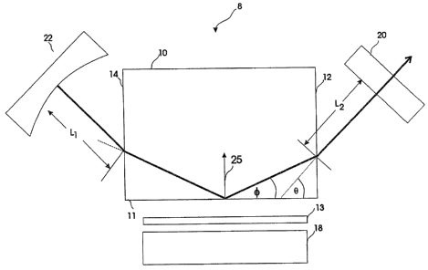
Referring to FIG.1 a solid-state laser 8 is formed of a block 10 of Nd:YV04 or
2~1~612
other solid-state laser material.13y way of example, the block 10 is a 3%
doped Nd:YVOq.
parallelepiped bar having dimensions of 10.1 mm by 2.5 mm by 3.0 man. Both a-
cut
polished flat ends 12 and 14 are parallel to each other and are anti-
reflection coated for a
wavelength of 1.06 Nm. An uncoated polished flat face 11 of the block 10 is
positioned to
receive light from a pumping source in the form of a laser diode bar 18
proximate to the
block 10. Alternatively, other pumping means pumping light at wavelengths
ranging from
200 to 2000 nanometers may be used. Emission from the laser diode 18 is
matched to the
mode volume of the laser by means of a fiber lens collimator 13.
In some cases the collimator may be unnecessary; the laser diode 18 could be
butted
1o against the block 10. Laser cavity forming means in the form of a partially
transmissive
output coupler mirror 20 and a highly reflective mirror 22, are shown adjacent
to ends 12
and 14 of the block respectively. 'The mirrors 20 and 22 are positioned at
angles to allow a
resonant mode having a beam to be reflected from the flat pumping surface at a
high angle
of incidence with respect to the normal (shown as 25) or grazing angle ~ of
approximately
10 degrees or less with respect to the flat face 11. Of course, due to the
difference in the
refractive index of the block 10 and the air interface surrounding the block,
the external
angle B shown in FIG.1 may be greater than 10 degrees. Although accurate
positioning of
the mirrors 20 and 22 is critical in obtaining the beam to be reflected from
the flat
pumping surface at a small grazing angle ~ of about 10 degrees or less, other
embodiments
2 ~ may be envisaged to achieve that end; for example the mirrors may be
integral with the
block 10 and the ends of the block cut so that they are slanted with respect
to the flat face
11 and coated with suitable reflective coatings to form a laser cavity.
lt~eferring to hIG.3 a laser mode having a diameter d~ is shown; the radius of
the
2 5 mode is r~ and the reflection angle is ~ . dE is of the order of 1/l0th of
the length of the
pumped region. The highest gain is at the pump face of the slab or block 10
and the gain
decreases exponentially away from the pump face in the direction of the arrow
25. In
order to extract as much energy from the pumped material (block 10) as
possible, the laser
mode radius rH should be comparable to the absorption depth 1/cx, where a is
the
3 0 absorption coefficient of the laser material at the pump wavelength, and
the beam
reflection angle ~ should be kept as small as possible so that the beam
travels through the
region of highest gain as it travels through the laser material.
in FIG.4 an amplifying means 40 is shown. The arrangement is similar to that
3 5 shown in hIG.3, however no mirrors are required.1~ laser beam 41 enters
the block 10 at
an angle ~ with respect to the flat pump face and reflects off the face of the
block at an
angle ~. The beam 41 is amplified as pump radiation is directed towards the
face 1 l and
into the block 10. A,s described above, to achieve high gain, preferably the
angle c~ should
4
-~ ~~~.8~~.2
be kept as small as possible.
Referring to FIGS, mirrors 20 and 22 are tilted at different angles to those
of
FIG.1; the resulting cavity formed by the mirrors is a ring cavity. This
arrangement
generates two output beams SO and 52; however, the same' configuration may be
used in
conjunction with a Faraday isolator to ensure unidirectional operation and
thus provide a
single output beam.
FIG.6 shows another embodiment of the ring cavity. Two diode pumping sources
18a and 18b pump opposing faces of the block 10 to generate two laser beams 66
and 68.
Of course, in both the embodiments of FIGS and 6 the angle ~ should be kept as
small as
possible.
Test Results
The performance was demonstrated with a bar of I~td:'S~V04 doped with 3~/o Nd.
The pump source was a 1 cm long quasi-CVi1 diode laser bar ~SDL model 3230.TZ)
which
produced 200 ps square pump pulses with energies of up to 12 mJ at a
repetition rate of
16 Hz. A 0.25 mm diameter fiber lens was used to partially collimate the diode
laser
2 o output so as to control the spatial extent of the pumping. °The
laser cavity was formed
between a concave high reflector (reflectivity Rl ~1) and a plane output
coupler (R2 =
0.475 -0.985) with a single bend due to total internal reflection located at
the centre of the
pump face. external angles, ~ ranged from 0 to 10 degrees. In order to assure
that the
curvature of the mode within the rod was small, the laser rod was located
close to the flat
output coupler. The radius of curvature of the high reflector arid the total
cavity length
were chosen to produce the maximum output energy and best quality laser mode.
For cavity parameters which gave a moderately small mode radius of 130 pm (L1
= 23 mm, radius r1 = 100 mm, L2 = 9 mm) the best beam quality was obtained at
an angle
3 0 of B = 4 degrees. At smaller angles the output pulse energy was higher but
the beam
showed a multianode structure caused by difl'raction at the rod ends and the
steep gradient
in the gain across the beam cross section. At angles greater than 6 degrees
the output
energy was even larger but the beam was stretched horizontally to a diameter
at least
twice that in the vertical direction: Some structwe in the horizontal
direction was also
3 5 present. At an external angle of 4 degrees the output beam appeared to be
Two and
was not sensitive to a small misalignment of the cavity mirrors or the
focusing of the pump
light. ~arefial measurement of the beam waist at the focus of a diffraction
limited lens and
the subsequent divergence gave values of M2 of approximately 1.3 and 3.9 in
the
5
~\ horizontal and vertical directions respectively. The apparently poor beam
quality in the
vertical direction was unexpected from the measured far-field beam profile.
Strong gain
variations in the vertical direction due to non-uniform pumping in that
direction are a
likely source of this large divergence.
The output pulse energy vs. the total uncorrected pump energy from the diode
bar
is shown in FIti. 2 (solid curves ) for output mirror reflectivities,1t2 of
0.475, 0.815, and
0.985. The highest output was obtained with ~t2 = 0.475 which indicates that
the gain was
high. Up to 2.3 mT was obtained for a pump energy of 12 md. The output pulses
were
to polarized parallel to the crystal c-axis and were approximately 200 us long
with no
observable oscillations. A maximum optical slope efficiency of 22% and an
optical to
optical conversion efficiency of 19% were obtained. If reflection losses at
the uncoated
fiber lens (n .1.5) and the pump face (ra a 1.96 for pump light polarized
perpendicular to
the c-axis) are included, these values increase to 27% and 23%, respectively.
The output energy from the laser varied with the temperature of the diode
pump.
Measurements of the absorption of the pump light as a function of the
temperature' of the
diode bar heat smk showed that the maximum output energy occurred at the same
temperature as the maximum absorption. A peak absorption coeffcient of
approximately
2 ~ 75 cm°1 was measured for light polarized parallel to the crystal c-
axis - more than twice
the value of 30 cm'1 measured for the perpendicular polarization which was
used in the'
present experiment. Since the output energy increased with absorption,
improved
efficiency may be achieved by rotating the pump polarization. However, the
required
additional optical elements complicate the present simple pumping arrangement.
The cavity losses can be estimate from the measured threshold pump energy for
a
range of output couples reflectivities. A loss per pass of 8% was found using
a modified
Findlay-Clay analysis of Tucker et al. as descn'bed in J. App. Phy. ~l'ol. 48
pp. 4907, 1977.
Some of this loss is e~cpected to be due to material absorption, scattering,
and reflection
3 0 losses at the total internal reflection surface. 3~owever, a calculation
of the laser mode size
inside the rod reveals that diffraction losses for our geometry were probably
significant.
The calculated mode radius for the cold cavity is approarimately 130 pm. For
an external
angh of ~ = 4~, the distance between the centre of the mode and the pump face
at the end
of the rod is only 160 pm, and therefore one can expect diffraction losses at
the ends of
3 5 the rod to play an important role.
Diffraction losses explain why the Laser mode was round for 8 = 40. At angles,
8
4o the losses were less severe and the high gain along the pump face caused
the mode to
6
~~~.~~~E
----
stretch out horizontally. Only at 40 did the diffraction losses balance the
tendency of the
gain to stretch the mode. To test this model, 8 was increased to loo and
cavity parameters
were chosen to give a larger mode which would experience higher diffraction
Losses. Since
a larger mode should also sample more of the pumped laser material, the output
energy
can be expected to increase.
These predictions were confirmed. Cavity parameters of r1 =1 m, Lg =102 rnm,
and L2 = 9 mm with ~ = l oo resulted in a good TEIVIoo mode with measured
ll~i2 values
of L.S and 1.6 in the horizontal and vertical directions, respectively. The
output pulse
energy as a function of the pump energy is shown in FhCr. 2 (dotted curves)
from which a
loss per pass of approximately 6% is obtained. An output of 3.2 mJ for a 12 m3
pump
pulse was obtained for an output coupler reflectivity of 0.815. The maximum
optical to
optical conversion efficiency corrected for reflection losses was 32% with a
slope
efficiency of 44%.
It is interesting to compare the suspected difl''raction losses for the cavity
parameters which resulted in the best mode profle at 40 and 100. The mode
radius
calculated for the cold cavity at 8 = loo is 330 lam. The ratio between this
value and the
distance between the pump face and the beam centre at the end of the rod is
330/400 =
0.83 compared to a ratio of 130/160=0.81 obtained for ~ = 40. Therefore the
diffraction
losses were roughly equal at the two angles. .
The observation of lasing at moderate pump energies and with output coupling
of
greater than 50% indicates that the gain within the laser material was high.
~e can use a
2 5 simple model to calculate the average small signal gain experienced by the
laser mode at '
threshold and then estimate the gain at higher pump energies.
For a pump pulse with a duration comparable to the fluorescence lifetime of
the upper
laser level, the maximum gain is given by,
g( Tp) = a N" ( Tp ) -_ (~::~.p(QE~B ~u Pp )l(hc) ( 1'exp (-Tp /~u ) J
where Tp is the period of the pump pulse, ~ is the stimulated emission cross
section, N"(t)
is the density of atoms in the upper laser Level at time t, 71.~ is the pump
wavelength, (QE)
3 5 is the quantum e~ciency of pumping to the upper laser level, fB is the
fraction of the
excited atoms which are in the appropriate sublevel of the upper laser level,
iu is the
fluorescence Lifetime, and Pp is the pump power absorbed per unit volume. For
pumping at
7
2~2~6~.
7~ = 809 nm, QE ~ 1 and fB - 0.52 for Nd:YV~4 reported by Tucker et al. The
stimulated emission cross section for Nd:Y'V04 is a factor of 2.7 larger than
that for
Nd:YAG (eyag = 6.5x10°19 cm2) or ayup4 =1.8 x 10⁻¹⁸ ~2, p, v~ue of ~u =
50 ps was
calculated from the measured decay of the fluorescence. This value is
approximately half
the fluorescence lifetime of 98 us measured for 1% Nd:YY~4 and indicates that
there was
significant concentration quenching at the high doping level used. Both the
value of the
stimulated emission cross section and the previously measured lifetime were
measured by
Tucker et al.
If we assume that the pump beam has a Gaussian profile with a 1/e2 half width
of yc
and is uniform along its length L~, then the power absorbed per unit volume in
the laser
medium, averaged across the mode diameter in the direction parallel to the
pump face and
at the average distance, due" of the laser mode ass from the pump face, is
given by
Pp = (1'~ap/2T.~pa~) exp(-apdav ) e~ f (~2) w / yol
Here, w is the mode°s 1/e~ radius, ap is the absorption coefficient for
the pump radiation,
and P~ is the total pump power (P~ = EdT~ where Eo is the total pump energy.
The error
function in Eq. 2 was approximately squat to 1 in all cases since y~ was
measured to be
less than 100 lrm. By substituting the appropriate values for day and B = 4o
and loo into
Eqs. 1 and ~, the small signal gain can be calculated. The results, calculated
at the
measured threshold pump energies (corrected for reflection losses), are listed
in Table 1
along with the threshold gain calculated from the mirror reflectivities and
the measured
distributed losses. The agreement between the two values is quite good.
Eqs. 1 and 2 can be used to estimate the small signal gain at higher pump
energies.
A gain coefficient of 8.4 cm°1 in the Nd:'YV04 at 8 = 4o is predicted
for a pump energy
of only 12 mJ. Such a high gain requires special precautions if it is to be
used in an
amplifier. For example, reflections o~the antireflection coatings can be
su~cient to
3 o produce lasing. Yndeed, in our experiment we observed self lasing at pump
energies
greater than 6 md, where the predicted small signal gain at the pump surface
was 5.4 cm°y.
This is in reasonable agreement with a predicted threshold gain of 6.5
cm°i expected for
our 0.15% reflective AIt coatings.
3 5 In conclusion, the use of a high absorption laser material in a slab
geometry with a
total internal reflection at a high angle of incidence has resulted in a laser
system with an
e~ciency and gain comparable to that obtained with the tightly folded
resonator
~' configuration. Aperturing by the laser rod itself has been found to be
critical in limiting the
effects of the high, non uniforan gain on the quality of the laser mode. The
simplicity of the
cavity design and the high optical to optical conversion e~ciency obtained for
an external
angle of ~ = l00 or an internal angle of approximately or less than 8 = So
make this laser
attractive for low power applications. It is especially suited to long pulse
applications or
high repetition rate q-switching using a CW pump. It should also be noted that
the
projection of the beam diameter along the length of the pumping surface is
approximately
equal to or less than the length of the pumped region.
~f course, numerous other embodiments may be envisaged without departing from
the spirit and scope of the invention.
Table 1:
Mirror Threshold Threshold Calculated
Reflectivity energy ( m~ gain ( cm-1) gain ( cm-1)
Nd:YV~4 4
.
0.475 0.45 0.45 ~ 0.38
0.815 0.17 0.19 0.14
0.985 0.091 0.090 0.077
Nd:Y\1~4 10
-
0.475 1.66 0.43 0.39
0.815 0.57 0.16 0.13
0.985 0.27 0.069 0.063