Note: Descriptions are shown in the official language in which they were submitted.
2118634
TITLE
Modular rail for mobile filing and storage systems.
FIELD OF THE lNv~ ION
The present invention relates to a modular rail
for use in the assembly of mobile filing and storage
systems that have cabinets each equipped with a roller
carriage at their lower part.
8ACKGROUND OF THE lNV~N ~ ION
Present mobile filing and storage systems are
assembled in place and, should there be a need to expand
the number of filing cabinets, it then becomes necessary
to disassembled the entire system in place and to install
new rails to correspond to the new demand. Evidently,
this is extremely time-consuming and expensive since the
rails already in place cannot be re-used for the expanded
system.
In certain cases, in order to avoid this
problem and to foresee expansion, an assembly greater
than that which is actually required is made resulting in
unnecessary floor occupation and expenses.
OBJECTS AND STATEMENT OF THE INVENTION
It is an object of the present invention to
overcome the above described problems of present systems.
2I1863~
_ - 2
This is achieved by providing a modular rail
that allows the assembly to be expanded to greater floor
area without the need of removing the rails already in
place.
Hence, the present invention is a rail that is
modular in that it is constructed in the manner that it
can be used so as to fit to any additions to the filing
and storage system, either in the longitudinal direction
of movement of the cabinet or in a direction
perpendicular to the latter.
The present invention therefore relates to a
modular rail for use in the assembly of a mobile filing
storage system that has cabinets equipped each with a
roller carriage; the rail comprises a longitudinal
metallic extrusion having a cross-section including:
a) a first section having an open side adapted
to receive therein one side of a floor structure over
which the filing and storage system is mounted,
b) an intermediate second section contiguous
with the first section adapted to receive thereon roller
members of the roller carriage, and
c) a third section contiguous with the second
section consisting of
i) first groove means adapted to receive
therein levelling means for vertically adjusting the
2ll8634
_ - 3
extrusion relative to a floor on which the filing and
storage system is supported, and
ii) second groove means adapted to
removably receive a cover adapted to extend over the
first groove means.
Other objects and further scope of
applicability of the present invention will become
apparent from the detailed description given hereinafter.
It should be understood, however, that this detailed
description, while indicating preferred embodiments of
the invention, is given by way of illustration only,
since various changes and modifications within the spirit
and scope of the invention will become apparent to those
skilled in the art.
IN THE DRAWINGS
Figure 1 is a perspective view of a mobile
filing and storage system in which the present invention
is used;
Figure 2 is a schematic top plan view of a
floor area to illustrate the modular feature of the
present invention;
Figure 3 is a cross-sectional view taken along
lines 3-3 of figure 2 with the addition of part of a
roller carriage;
_ 4 _ 2118 6 3 ~
Figure 4 is a cross-sectional view taken along
lines 4-4 of figure 2 with the addition of part of a
roller carriage;
Figure 5 is a cross-sectional view taken along
lines 5-5 of figure 2 with the addition of part of a
roller carriage;
Figure 6 is a cross-sectional view taken along
lines 6-6 of figure 2;
Figure 7 is a cross-sectional view taken along
lines 7-7 of figure 2;
Figure 8 is an end view as seen from lines 8-8
of figure 2; and
Figure 9 is an end view as seen from lines 9-9
of figure 2.
DESCRIPTION OF PREFERRED EMBODIMENTS
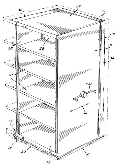
Referring to figure 1, there is shown a mobile
filing and storage system, generally designated 10, that
includes a filing cabinet 12 adapted to move
longitudinally in the direction of arrow 14, the cabinet
is supported and guided in a pair of parallel rail
structures 16 and 18 mounted at opposite sides of a floor
structure 20.
The filing cabinet 12 includes a top panel 22,
two vertical side panels 24 and 26, a rear panel 28 and
a series of vertically spaced shelves 30, the lower shelf
32 of which also acts as the roller carriage allowing the
~,~21 1 8634
-- 5
cabinet to be moved, manually, mechanically or
electrically, along the rails. The detailed description
of the roller carriage is made part of a co-pending
patent application filed concurrently herewith by
S applicant.
Figure 1 shows also parts of two adjacent
panels 34 and 36 which, according to the present
invention, may be added to the filing and storage system
without the necessity of completely disassembling the
various above described components of the filing system.
Referring to figure 2, the schematic
representation illustrates the versatility of the present
invention wherein, from a system that would include
initially, for example, filing cabinets over floor areas
A and C, it is possible to add cabinets over floor areas
B and D as well as in areas E, F, G, H, I, in the latter
case of which it would be required to add to rails 16, 18
and 38, three similar rail sections 16', 18' and 38'.
Figures 3, 4 and 5 are cross-sectional views
taken from figure 2 with the addition, however, of part
of the lower roller carriage in order to better
illustrate the purpose of the present invention.
Referring also to figure 6, a floor structure usually
includes a rectangular panel 42 of plywood covered with
~2118634
a carpet 44 and supported by a series of laterally spaced
longitudinal metallic tubular structures 46.
Each modular rail structure 16, 18, 38 of the
present invention consist essentially of a longitudinal
metallic extrusion comprising a first section formed of
walls 48, 50 and 52 which receive the ends of the
metallic tubular structures 46 and of two additional
walls 54 and 56 which receive the plywood panel 42 with
its carpet 44. Contiguous with the first end section, is
lo an intermediate second section or central section
consisting of vertical walls 58 and 60, each having
opposite inward horizontal extensions 62 and 64,
respectively, thus defining a U-shaped recess into which
a roller bearing plate 66 iS slidably received and
15 supported. The lower part of this second rail section
encloses a tubular member 68 which serves as a
reinforcement for the closed channel formed by side wall
50 of the first section, top wall 70 of the upper recess,
side wall 72 and bottom wall 74, the latter being an
20 extension of the bottom wall 48 of the first section.
The rail further includes a third or opposite
end section which is contiguous with said intermediate
second section and which consists essentially of a first
groove means and a second groove means. The first groove
means is adapted to receive a leveling means for
vertically adjusting the metallic extrusion relative to
.
~,~21 18634
-- 7
the floor on which the system is supported and the second
groove means is adapted to removably receive a cover
adapted to extend over said first groove means.
Structurally, this opposite end section which includes
the side wall 60 of the second section, a U-shaped groove
defined by side wall 72 of the second section and
opposite side wall 78 from which extends an outwardly
inclined ramp 80. The groove formed by opposite side
walls 72 and 78 displays a series of longitudinal
parallel ribs while the bottom wall 82 is tapped with a
hole so as to receive therethrough the threaded stem 84
of a levelling bolt 86, the head of which rests on floor
88. The upper edge of wall 60 is grooved so that a
flange 90 of a flexible cover 92 may be snapped or slid
into engagement to hide and protect the groove into which
are mounted the levelling bolts 84. The lower edge 94 of
the cover rests on ramp 80. The cover has a projecting
flange 95 which further secures it in place.
A further section of the rail is formed of
walls 52, 54 and 58 into which may fit an anti-tilt
device 96 secured to the roller carriage and having a
portion 98 extending into the said further section.
As shown in figure 4, carriage 32 has rollers,
one of which is indicated at 104, mounted to a shaft 102
which is rotated by operating handle 100 (see figure 1)
to which it is appropriately connected. These rollers
~ ~ 21 1 8634
-- 8 --
are supported on plate 66. The opposite side of the
floor structure A is received within the rail structure
18 which is constructed identically to the rail structure
16 described above and illustrated in figure 3. Whenever
it is desired to add filing cabinets in other areas such
as B and D, a slightly modified floor structure C is used
in which one extremity of the floor is identical to the
sides of floor structur`e A while the other side is
constructed as illustrated in figure 4 with a section 106
which has an extension 108 that projects beyond the
plywood 42 and rests on the upper face 110 (see figure 3)
of the rail structure. This extension 108 has proper
openings allowing a series of longitudinally spaced
screws 112 to fit into the U-shaped groove 114 and to
secure the floor structure to the rail. A recessed area
116 in the bracket 106 permits location of the ramp 80
therein. To prevent dust from entering the two chambers
118 and 120, similarly constructed flexible covers 122
and 124 are snapped in their respective grooves 126 and
128 of the rail.
Figure 5 shows a roller 130 mounted at the
opposite end of the lower carriage 32' of the filing
cabinet 36, the roller being supported on plate 66'
received within a rail 31 which is identically shaped to
rails 16 and 18 described above. The opposite side of
the floor structure C is constructed identically to the
sides of panel of floor area A. In this case, a cover
~2118634
92 ' is used to hide and protect the area of the
longitudinal groove in which the levelling means 84', 86'
extend.
Referring to figure 2, whenever it is wished to
add file cabinets in floor areas B and D, rails 16 ', 18 '
and 38 ' are positioned to abut the ends of rails 16, 18
and 38, respectively. In order to ensure a tight
connection between the respective rails, a plate 150 is
positioned within a channel located underneath the recess
in which plate 66 is supported. This plate 150 extends
between the intersecting line 152 (see figure 2) and is
secured therein by means of a fastening screw 154; its
opposite ends are bevelled so as to match with the
bevelled ends of plate 66 thereby avoiding an
intersecting line perpendicular to the travel of the
roller.
Figures 7, 8 and 9 represent the components
used at the extremities of rails 16 ', 18 ' and 38 '
respectively. In figure 7, the end plate 160 has an
20 upper inwardly projecting part 162 that serves as a
stopper for the roller when rolling on plate 66.
Figure 8 shows the end plate 170 with its upper
inwardly projecting part 172 having a stopper function
similar to that of 162 in figure 7. Screws 174 secure
A :
_ ~21 1 8634
-- 10 --
the plate 170 by engaging corresponding slots 176 (see
figure 3) at the lower part of the ramp 80.
Figure 9 also shows an end plate 180 with a
stopper 182 and fastening screws 184. This end plate
displays a curved portion 186 that conforms with the
curved portion 92 of the flexible cover.
Although the invention has been described
above in relation to one specific form, it will be
evident to a person skilled in the art that it may be
modified and refined in various ways. It is therefore
wished to have it understood that the present invention
should not be limited in scope, except by the terms of
the following claims.
,? A'