Note: Descriptions are shown in the official language in which they were submitted.
211~671
. .
AIR CH~MBER ACTUATOR FOR A PERFORATING GUN
Backuround Of Th8 Invention
1. Field Of The Invention
The present invention relates generally to methods and
apparatus for perforating wells.
2. De~cription Of The Prior Art
One operation commonly performed in the completion of an oil
or gas well is the perforation of the steel casing of the well
to communicate the well bore with a subsurface formation
intersected by the well. Thus, rormation fluids are allowed to
be produced from the formation through the perforations and up
through the well bore.
Many techniques have been used in the past to actuate
perforating guns to accomplish the formation of the perforations.
For example, perforating guns have been actuated: (1)
electrically; (2) through drop bar mechanisms; and (3) through
pres~ure actuated mechanisms.
One commonly used technique for conveying the perforating
guns and associated apparatus into the well is to assemble the
same on a tubing string thus providing what is commonly referred
to as a tubing conveyed perforating system. Such tubing conveyed
perforating systems are available from the Halliburton Reservoir
Services division of Halliburton Company, the assignee of the
present invention.
One commonly used operating system for tubing conveyed
perforating systems i9 a firing head which operates in response
to a pressure differential. The pressure differential is created
by applying increased pressure either to the tubing string or to
the annulu~ surrounding the tubing string and conveying that
2118671
":
increa~ed pressure to an actuating piston contained in the firing
head. Typically, such a firing head will have hydrostatic
pressure balanced across the actuating piston as the tool is run
into the well. When it is desired to operate the tool, increased
pressure is applied to one side of the actuating piston. Thus,
the low pressure reference for the actuating piston is
hydrostatic pressure, and a pressure differential is created by
increasing pressure on the high pressure side of the piston above
hydrostatic pressure. One example of such a system is the Vann
Systems differential firing head shown at page TCP-1020 of Vann
Systems Engineered Well Completion Product Catalog.
Another approach of the prior art has utilized an isolated
atmospheric chamber contained within a firing head as a low
pressure reference zone. For example Vann Systems Pressure
Actuated Firing Head shown at page TCP-1022 of Vann Systems
Engineered Well Completion Product Catalog illustrates a firing
head operating in response to increased tubing pressure which
creates a pressure differential as compared to an atmospheric
pressure chamber which i~ in constant communication with the low
pressure side of the actuating piston.
The prior art also includes dual firing heads such as Vann
Model APF-C as ~hown at page TCP-1028 of Vann Systems Engineered
Well Completion product catalog.
There are sometimes disadvantages to using firing heads
which require substantial pressure to be applied to the tubing
or well casing to provide the increase in pressure which actuates
the tool. In some instance~, the pressures necessary to actuate
the tools may be excessively high. Also, in many well
; J
~-~ 211~671
perforation jobs it is desirable to perforate in an underbalanced
condition, that is with a relatively low pressure present in the
well when perforating occurs, and thus if high pressures are
applied to actuate the perforating gun, it is necessary to be
able to bleed off those high pressures very rapidly before the
well is actually perforated.
On the other hand, in many situations it is undesirable to
use drop bar actuated firing heads or electrically actuated
firing heads.
Thus it is seen that there is a need for a pressure actuated
firing system which can avoid or eliminate the application of
excessively high pressures.
Summary Of The Tnvention
The present invention provides improved methods and
apparatus for perforating oil and gas wells with a firing head
which operates in response to a pressure differential. This
result is achieved in a novel fashion through the use of an
atmospheric pressure chamber which is lowered into a well on a
wireline and brought into operative engagement with a firing head
contained in a tubing conveyed perforating string.
The firing head of the tubing conveyed perforating string
includes a differential pressure actuating piston which initially
has hydrostatic pressure balanced thereacross. The atmospheric
pressure chamber is brought into communication with a low
pressure side of the actuating piston thus creating a pressure
differential wherein the high pressure is hydrostatic pressure
and the low pressure is substantially atmospheric pressure.
:~ 21~8671
Thus a differential pressure actuation iB provided without
the need for applying excessive operating pressures to the tubing
string. In one embodiment, no pressure i9 required to be applied
to the tubing string.
Numerous objects, features and advantages of the present
invention will be readily apparent to those skilled in the art
upon a reading of the following disclosure when taken in
con~unction with the accompanying drawings. `
Brief De~cription Of The Drawin~
FIGS. 1-3 comprise a sequential series of schematic
illustrations of a tubing conveyed perforating system utilizing
a firing head actuator having an atmospheric pressure chamber
with a timer controlling operation of the pressure chamber.
FIGS. 4A-4H comprise an elevation sectioned view of a first
embodiment of the invention utilizing a pressure actuated
pyrotechnic timer associated with the atmospheric pressure
chamber.
FIGS. 5A-5D comprise an elevation sectioned view of the
upper portions of a second embodiment of the invention utilizing
an electric self-contained timer for operating the atmospheric
pressure chamber actuator.
Detailed DescriPtion Of The Preferred Embodiments
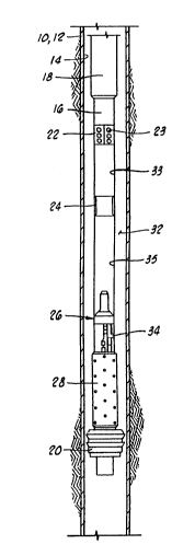
Referring now to the drawings, and particularly to FIGS. 1-
3, a well 10 is represented schematically by a well casing 12
having a well bore or casing bore 14 defined therein. A portion
of a tubing string 16 is shown in place within the well bore 14.
It will be appreciated that the tubing string 16 is lowered into ;
~ 211~7~ :
the well bore 14 from the earth's surface and the tubing string
6 will initially extend entirely to the surface of the well.
In FIG. 1, only a lower portion of the tubing strin~ 16 is
illustrated and an on/off tool 18 has been disconnected from an
upper tubing string portion so as to leave the lower portion 16
of the tubing string in place within the well bore. An auto
release gun hanger 20 on the lower end of the tubing string 16
anchors the tubing string 16 in place within the well bore 14.
The tubing string 16 has assembled therewith a perforated
nipple 22, a seating nipple or landing nipple 24, a differential
firing head 26, and a perforating gun 28.
Although not illustrated in FIG. 1, the upper portion of the
tubing string 16 above the on/off tool 18 may carry a
conventional packer if desired and the auto release gun hanger
may be eliminated iL the tubing string 16 i9 suspended in the
well from the drawworks located at the earth's surface or from
a packer assembled with the tubing string.
The present invention is not directed to the~e details of
the manner in which the tubing conveyed perforating string is
retained in the well, but instead deals only with the preferred
mechanisms and methods for actuating the tubing conveyed
perforating string. Thu~ the other details commonly associated
with a tubing conveyed perforating string will not be illustrated
or described in detail and will be understood to be conventional
n manner.
The differential firing head 26 contains an actuating piston
60 (see FIGS. 4F-4G). A high pressure side 92 of the actuating
piston 60 is communicated with a well annulus 32 between tubing
2118671
string 16 and well bore 14 through a high pressure inlet 34. A
low pressure side 100 of the actuating piston 60 is communicated
with a lower portion 35 of the tubing bore of tubing string 16
below the seating nipple 24.
The seating nipple 24 can be described as dividing the bore
of tubing string 16 into an upper tubing bore portion 33 located
thereabove and a lower tubing bore portion 35 located therebelow.
The lower tubing bore portion 35 can be generally referred
to as a low pressure reference zone 35 communicated with the low
pressure side 100 of actuating piston 60. The well annulus 32
can generally be referred to as a high pressure reference zone
communicated with the high pressl~re side 92 of actuating piston
60.
It will be seen that as the tubing string 16 is run into the
well as illustrated in FIG. 1, hydrostatic pressure in the well
annulus 32 and within the tubing string 16 is balanced through
communication ports 23 of perforated nipple 22 and thus iB
balanced across the actuating piston 60 contained in differential
firing head 26.
In FIG. 2, the tubing string 16 has been placed within the
well and a firing head actuator generally designated by the
numeral 36 has been landed in the seating nipple 24. The firing
head actuator includes a low pressure chamber 38 which preferably
is an atmospheric chamber filled with air at substantially
atmospheric pressure.
The firing head actuator 36 is representative of the
embodiment shown in FIGS. 5A-5D of the application. Firing head
actuator 36 includes an electric timer means schematically
2118671
designated as 40. Firing head actuator 36 includes an
electromechanical valve 42 which controls communication of the
atmospheric chamber 38 with the lower tubing bore 35. A control
system schematically illustrated at 44 i9 responsive to the timer
means 40 and controls the valve means 42~
Prior to placement of the firing head actuator 36 in the
well 10, the electric timer means 40 is preset so as to allow a
predetermined amount of time to pass before the valve 42 is
opened. The firing head actuator 36 iS then run into the tubing
string 16 on a wireline or slick line and is landed in the
seating nipple 24 as illustrated in FIG. 2. Then after the timer
means 40 times out, the control system means 44 will move the
valve 42 from the closed position shown in FIG. 2 to the open
position represented in FIG . 3 thus allowing fluid trapped at
hydrostatic pressure within the lower tubing bore portion 35 to
flow into the atmo~pheric chamber 38 as represented by arrows 46
thus reducing the pressure on the low pressure side 100 of
actuating piston 60 of differential firing head 26. High
pressure fluid from well annulus 32 will flow in the high
pressure inlet 34 as represented by arrows 48 thus moving the
actuating piston 60 of differential firing head 26 and causing
differential firing head 26 to fire the perforating gun 28.
The preset electric timer means 40 allows the well 10 to be
placed in an underbalanced condition prior to running the firing
head actuator 36 into the well, because the firing head actuator
can be operated in response to electric timer means 40 without
the need to apply increased pressure to the tubing string 16.
118671
.
The Embodiment_O~ FIGS. 4A-4H
Turning now to FIGS. 4A-4H, a detailed description of one
embodiment of the invention i9 provided. The embodiment
illustrated in FIGS. 4A-4H differs somewhat from that
schematically illustrated in FIGS. 1-3. The primary difference
is that the differential firing head shown in FIGS. 4A-4D
utilizes a pressure actuated pyrotechnic time delay device to
open the atmospheric pressure chamber, instead of using an
electric timer.
In FIGS. 4A-4H, a portion of the tubing string 16 is shown
including the landing nipple 24 (see FIG. 4A), the differential
pressure firing head 26 (see FIGS. 4E-4H), and the perforating
gun (see FIG. 4H). In the embodiment illustrated in FIGS. 4A-4H,
the auto release gun hanger 20 has not been utilized.
The seating nipple 24 preferably is an Otis R Nipple
available from the Otis Engineering division of Halliburton
Company, the assignee of the present invention, such as shown at
page 94 of the Otis Products and Services Catalog OEC 5516
(1989). The seating nipple 24 has a seal bore 50 defined therein
and has internal recesses 52 and 54 in which a latching device
may be received. The seal bore 50 may also be referred to as a
seat 50.
The differential firing head 26 which is seen in FIGS. 4E-4F
actually includes two independent firing mechanisms, either one
of which may be considered a primary firing mechanism with the
other being a backup firing mechanism.
As seen in FIG. 4E, a stinger 56 extends upward from firing
head 26 within the lower tubing bore portion 35. Stinger 56 is
2118671
-
preferably a stinger of a VannJet firing head available from the
Vann Systems division of Halliburton Company, the assignee of the
present invention, as illustrated at page TCP-1018 and 1019 of
the Vann Systems Engineered Well Completion Product Catalog. The
VannJet stinger 56 is of a type well known in the art and it will
not be described in detail herein. It is utilized with a VannJet
firing head (not shown) which is lowered into the tubing string
on a wireline (not shown) and received over the stinger 56 to
initiate burning of a first pyrotechnic pathway 58 in response
to a pressure increase within the tubing string 16 applied to the
VannJet firing head. The pyrotechnic pathway 58 may include
pyrotechnic time delay devices.
The present invention is concerned primarily with the other
firing mechanism of firing head 26, namely a differential
pressure actuating piston 60 seen in FIGS. 4F-4G.
The differential firing head 26 can be described as having
a firing head housing assembly 62 which includes an upper housing
adapter 64 to which the stinger 56 is attached at threaded
connection 66.
Housing assembly 62 further includes a tubing connector
housing 68, a shear pin housing 70, a ported housing 72, a firing
pin housing 74 and a lower adapter 76 all of which are connected
together by conventional threaded connections with O-ring seals
provided at appropriate places as illustrated in the drawings.
An inner housing cavity generally designated as 78 is
defined within the housing 62 between an inner mandrel 79 on the
inside and tubing connector housing 68, shear pin housing 70, and
ported housing 72 on the outside. The annular housing cavity 78
r
- 2~L18671
receives the previously mentioned actuating piston 60 and other
associated structure as will now be described.
The actuating piston 60 includes a lower portion 80 having
an outer cylindrical surface 82 closely received within a bore
84 of ported housing section 72. An O-ring seal 86 is received
within an annular groove defined in the bore 84 and provides a
sliding seal between bore 84 and the piston 60.
The piston 60 has an inner bore 86 defined therethrough
which is closely received about an outer cylindrical surface 88
of inner mandrel 79. An O-ring seal 90 is carried by piston 60
and seals between bore 86 and outer surface 88.
An annular differential pressure area of piston 60 is
defined between inner O-ring 90 and outer O-ring 86 as seen in
FIG. 4G. A lower end 92 of piston 60 below this differential
area may be defined as a high pressure side 92 of piston 60, and
is communicated with the well annulus 32 through high pressure
port 34 defined in ported housing section 72.
Actuating piston 60 has an enlarged diameter intermediate
portion 94 which in the initial position of FIG. 4G has a
downward facing shoulder 96 abutting an upper end 98 of ported
housing section 72.
An upper end 100 of piston 60, which may also be referred
to as a low pressure side 100 of piston 60 above seals 86 and 90,
is communicated with the upper portion of inner housing cavity
78 and is thereby communicated through a port 102 with an
external conduit 104 which is communicated through a port 106
seen in FIG. 4B with the lower tubing bore portion 35. It is
noted that the external conduit 104 could be replaced by an
211~671
. . .
11
internal passage (not shown) communicating annular cavity 78 with
lower tubing bore portion 35.
The upper end 100 of actuating piston 60 initially abuts an
inner ring 108 of a shear sleeve set generally designated by the
numeral 110. A plurality of shear pins such as 112 ini-tially
hold the actuating piston 60 against upward movement relative to
the outer housing assembly 62. As will be further described
below, when a sufficient upward differential pressure is applied
across actuating piston 60, the shear pins 112 will shear thus
allowing the actuating pistor. 60 to move upward.
In the initial position of actuating piston 60 as seen in
FIG. 4G, a firing piston 114 is associated therewith. Firing
piston 114 includes a plurality of inner sealing rings 116 which
engage an outer surface 118 of inner mandrel 79, and includes a
plurality of outer ~eals 120 which engage a bore 122 of ported
housing section 72. A plurality of collet fingers 124 extend
upward from firing piston 114 and have enlarged heads 126 thereon
which are initially held by actuating piston 60 in a retracted
position wherein the enlarged heads 126 are received within a
groove 128 defined in inner mandrel 79.
As will be apparent in viewing FIG. 4G, when the upward
pressure differential acting on actuating piston 60 is sufficient
to shear pins 112 and move actuating piston 60 upward, the
enlarged heads 126 of collet fingers 124 will be released and
then hydrostatic pressure entering high pressure port 34 will act
downward on firing piston 114 to move it downward. A sealed low
pressure cavity 130 communicates with a lower end 132 of firing
piston 114.
-`" 2118671
;.
12
When the firing piston 114 moves downward, it will strike
a firing pin 134 thus initiating burning of various elements
comprising a second pyrotechnic pathway 136 which will ultimately
result in the firing of perforating gun 26 in a conventional
manner. The second pyrotechnic pathway 136 may include
pyrotechnic time delay devices.
In FIGS. 4A-4D, the details of a firing head actuator 138
are shown. The firing head actuator 138 seen in FIGS. 4A-4D is
an alternative embodiment of the firing head actuator 36 which
was generally described in reference to FIGS. 2 and 3. As
previously noted, the firing head actuator 138 of FIGS. 4A-4D
does not use an electrical timer like described with reference
to FIGS. 2 and 3 but instead uses a pyrotechnic time delay
device.
After the tubing string 16 is placed within the well as
schematically illustrated in FIG. 1, the firing head actuator 138
is lowered down into the tubing string 16 on a wireline or slick
line and is landed in the seating nipple 24. FIGS. 4A-4D
illustrate the firing head actuator 138 after it has been landed
in the seating nipple 24.
Firing head actuator 138 includes a locking mandrel 140
which has a latch mechanism 142 which latches into the grooves
52 and 54 of seating nipple 24. Locking mandrel 140 carries an
outer packing or seal 144 which seals within the seal bore or
seat 50 of seating nipple 24. Locking mandrel 140 is preferably
an Otis Model lORO or Model 710RO lock mandrel available from the
Otis Engineering division of Halliburton Company, the assignee
of the present invention, and designed for use with an Otis R
211~671
...
landing nipple, as is illustrated for example at page 94 of the
Otis Products and Services Catalog OEC 5516 (1989).
The locking mandrel 140 supports the remaining portions of
the firing head actuator 138 therebelow suspended from the
seating nipple 24. The locking mandrel 140 and various other
components of the firing head actuator 138 attached thereto are
run into the tubing string 16 by a wireline and a running tool
(not shown) which releasably latches into the locking mandrel
140. The running tool may be an Otis 'R' Running Tool such as
Model 41R018701 available from the Otis Engineering division of
Halliburton Company.
An equalizer valve 145 having an equalizer housing 146 is
connected to the lower end of locking mandrel 140 at threaded
connection 148. A plurality of equalizing ports 150 extend
through equalizer valve housing 146 and communicate the lower
tubing bore portion 35 located therebelow through an inner bore
152 of lock mandrel 140 with the upper tubing bore portion 33
located above seal bore 50 of seating nipple or landing nipple
24. As seen in the lower portion of FIG. 4A, a sleeve valve
element 154 is slidably received within a bore 156 of equalizer
valve housing 146 with upper and lower O-ring seals 158 and 160
provided therebetween. The equalizer valve 145 may be an Otis
20R018701 available from the Otis Engineering division of
Halliburton Comapny.
When the locking mandrel 140 is initially run into the
tubing string 16 on the wireline running tool (not shown), the
sliding sleeve valve element 154 is located downward relative to
equalizer valve housing 146 from the position shown in FIG. 4A,
'~ . . ' ',, ' ': -: ':i: .::: .::: :~: .::::: '::: ' ': . ' . : ' : : :;: ' :: . : ' . . :: - ;:' ', ': ': ' : i. ' ,,, ' , ' : i' ' - ' ,: " ,
` 2118~71
14
so that the upper seal 158 is located below the isolation ports
150. When the wireline running tool is withdrawn from the
locking mandrel 140, it pulls the sleeve valve element 154 upward
to the position of FIG. 4A wherein the equalizing ports 150 are
closed thus isolating the lower tubing bore portion 35 from the
upper tubing bore portion 33 and thus from the well ann~lus 32
so that any changes in hydrostatic pressure within the well 10 ;
are no longer balanced across the actuating piston 60. ;
The firing head actuator 138 can be described as having an
actuator housing assembly 162 which includes the equalizer valve
housing 146, actuator piston housing 164, shear pin housing 166,
housing coupling 168, time delay housing 170, upper atmospheric
chamber end wall housing 172, atmospheric chamber housing 174,
and lower housing plug 176. ~-
An actuator piston 178 has outer O-rings 180 and 182 which
seal within a bore 184 of actuator piston housing 164.
The actuator piston 178 has a lower end 186 which abuts an
upper end 188 of an actuator firing piston 190. Actuator firing
piston 190 carries an upper O-ring seal 192 and lower seals 193
and 195, all closely received within upper bore 194 of shear pin
housing 166. A plurality of shear pins 196 initially hold the
actuator firing piston 190 in place relative to shear pin housing
166. Actuator piston 190 carries a firing pin 198 on its lower
end.
A percussion type pyrotechnic initiator 200 is located below
firing pin 198 as seen in FIG. 4B. Operatively associated with
percussion initiator 200 are first and ~econd pyrotechnic time
delay devices 202 and 204 each of which takes a predetermined
211~671
time to burn thus providing a predetermined time delay between
striking of initiator 200 by firing pin 198 and the completion
of burning of the time delay devices 202 and 204.
A shaped explosive charge 206 is located below second time
delay device 204 and operatively associated therewith so that
explosive charge 206 is detonated by second time delay device 204
after the predetermined time delay. More than two-time delay
devices may be used to provide greater time delays.
The upper atmospheric end wall housing 172 closes the upper
end of the low pressure chamber 38 thus sealing the same. An
upper end wall 208 of atmospheric chamber 38 is defined by the
upper atmospheric chamber end wall housing 172. An open bore 210
is located immediately below shaped charge 206 and leads to the
upper end wall 208. A communication bore 212 extends
diametrically through the upper end wall 208.
When the shaped charge 206 explodes, an explosive jet will
extend downward therefrom through the open bore 210 and will
pierce the upper end wall 208 into the atmospheric chamber 38,
and intersecting the communication bore 208. Thus, upon firing
of the shaped charge 206, the atmospheric chamber 38 will be
placed in communication with the lower tubing string bore portion
35 through the communication bore 212.
It will be recalled that well fluid at substantially
hydrostatic pressure was previously trapped in the lower tubing
string bore portion 35 and against the upper end or low pressure
side 100 of actuating piston 60. When the shaped charge 206
fires and pierces the upper end wall 208, the pressure trapped
in lower tubing bore portion 35 will be vented into the
211~671
:`
16
atmospheric chamber 38 thus substantially immediately reducing
the pressure seen by the low pressure side 100 of actuating
piston 60 to approximately atmospheric pressure. Since
hydrostatic pressure is still seen by the high pressure side 92
of actuating piston 60, a large upwardly acting pressure
differential will be immediately present across actuating.piston
60 thus providing sufficient force to shear shear pins 112 and
to move actuating piston 60 upward. Upward movement of actuating
piston 60 releases the firing piston 114 which will then be moved
downward by the pressure differential acting across firing piston
114. The downward moving firing piston 114 will strike firing
pin 134 thus initiating the pyrotechnic path 136 which will in
turn fire the perforating gun 28.
The shaped charge 206 and associated apparatus may be
generally described as an operating means 206 for communicating
the lower tubing bore portion 35 with the atmospheric chamber 38
so as to drop pressure in the lower tubing bore portion 35 and
to actuate the differential firing head 26.
The actuator piston 178, actuator firing piston 190 and
percussion initiator 200 may be collectively described as a
pressure responsive initiator means for initiating burning of the
time delay devices 202 and 204. The time delay devices 202 and
204 may be generally described as a timer means for providing a
preset time delay between ætarting of the timer means with
initiator 200 and operation of the shaped charge 206 to
communicate the atmospheric chamber 38 with the lower tubing bore
35 and to thereby move the actuating piston 60 and fire the
perforating gun 28.
.: - : : : :: :.. :::: .: .. ,: : . , , . ~, , : , ;: ,
. . ..... ., ., . i . ... .. . .... . . ... .. . . ...... ... . .. ... .. ... ........... . . . .
2118671
The ~hodiment Of FIGS. 5A-5D
FIGS. 5A-5D compriBe an elevation sectioned view of the
firing head actuator 38 with an electric timer means 40 as was
schematically shown in FIGS. 2 and 3. The tubing string 16 and
various components thereof previously described are the same in
the embodiment of FIGS. 5A-5D and thus like numerals are used to
identify those parts as were used in FIGS. 4A-4H.
The firing head actuator 36 includes a locking mandrel 140
and the equalizer valve 145 just as was utilized with the firing
head actuator 138 of FIGS. 4A-4H.
The firing head actuator 36 includes an actuator housing
assembly 214 which includes the equalizer valve housing 146, a
housing adapter 216, an electronics housing 21~, a motor housing
220, a housing adapter 222, a valve housing 224, an air chamber
adapter 226, an air chamber housing 228, and lower end plug 230.
A battery pack 232 and an electronics package 234 are
located in electronics housing 218 and are connected by power
cable 236 to an electric motor 240. The electronics package 234
includes timer means 40. An elastomeric shock absorber ball 231
is located between the upper end of battery 232 and a plug 229
received in housing adapter 216. The timer means 40 includes
circuitry which can be set to provide a predetermined elapsed
time in the range of from one hour to seven days which will run
after the timer 40 is set and before the motor 240 begins to
operate. The motor 240 is part of the operating means 44 in
FIGS. 2 and 3.
After the time determined by timer 40 has elapsed, the motor
240 rotates a lead screw 242 which is held longitudinally in
2118671
~
18
place between bearings 244 and 246. Lead screw 242 drives a
threaded collar 248 upward relative to the housing assembly 214.
A lug 249 extends from collar 248 into slot 251 of housing
adapter 222 to prevent rotation of collar 248. The threaded
collar 248 has an elongated slot 250 defined therein within which
is received a lug 252 attached to a valve stem 254. Valve stem
254 has a valve member 256 defined on a lower end thereof. Valve
member 256 is initially closely received within a bore 258 of air
chamber adapter 226 with a pair of O-ring seals 260 sealing
therebetween.
As will be apparent in FIG. 5D, when the valve member 256
is in its lowermost position as illustrated in FIG. 5D, the O-
ring seals 260 and valve member 256 block the bore 258 thus
closing the atmospheric chamber 38.
After the electronic timer 40 determines that the preset
time delay has elapsed, it will cause the electric motor 240 to
rotate the lead screw 242 thus pulling collar 248 upward. The
collar 248 will move upward until a lower end 262 of slot 250
engages lug 252 and then pulls valve stem 254 upward thus pulling
the O-ring seals 260 out of engagement with bore 258 thus
permitting the atmospheric chamber 38 to be communicated with the
lower tubing bore portion 35 through a port 264 defined in valve
housing 224. This in turn causes actuating piston 60 to release
firing piston 114 to fire perforating gun 28.
The electronic timer means 40 can be constructed in a manner
similar to that disclosed in U. S. Patent Application Serial No.
07/868,832 of Schultz et al., entitled SHUT-IN TOOLS filed April
. ~ .,; .. . . .. . . . .
2118~71
19
14, 1992, the details of which are incorporated herein by
reference.
It will be appreciated that with the firing head 36 of FIGS.
5A-5D, it is necessary to start the electric timer means 40
running before the firing head actuator 36 is run into the tubing
string 16 on the wireline (not shown). Thus, the timer means 40
will be preset for a sufficient time to allow the firing head
actuator 36 to be run into the tubing string 16, and landed in
the landing nipple 24 prior to the time the timer means 40 times
out and initiates the actuating sequence which fires perforating
gun 28.
Alternatively, it is noted that the firing head actuator 36
utilizing the electronic timer 40 could be modified by equipping
it with a rupture disc which would be sheared due to pressure
encountered at a predetermined depth and thus the electronic
timer could in fact be started downhole in response to an
increase in pressure. If that modification i9 made, however, the
only advantage of the electronic timer system over the
pyrotechnic time delay provided by firing head actuator 138 is
that much longer time delay intervals may be programmed with the
electronic timer.
Summary Of O~eration
The operation of the systems shown in FIGS. 1-5 can be
generally summarized as follows.
The systems provide methods of perforating the well 10 which
include a first step of assembling on the tubing string 16 the
perforating gun 28 and the differential pressure firing head 26
21~8671
including the actuating piston 60 having the high pressure side
92 and the low pressure side 100.
Then the tubing string 16 is run into the well 10 to a
location wherein the perforating gun 28 is adjacent a subsurface
zone which is to be perforated.
Next, all surface equipment is installed and pressure
testing is completed. Hydrostatic pressure in the well is then
adjusted by swabbing, gas lift or other procedure to create the
desired underbalance in the well.
Then, the selected firing head actuator 36 or 138 is run
into the tubing string 16 on a slick line (not shown) and landed
in the landing nipple 24. The firing head actuator 36 or 138
includes a low pressure chamber 38.
As the tubing string 16 is run into the well, hydrostatic
pressure in the well and i~ tubing string 16 ii3 balanced across
the actuating piston 60 since communication is provided through
the perforated nipple 22. When the firing head actuator is
landed in the landing nipple 24, the slick line and running tool
are withdrawn and the equalizer valve 145 is closed. When
equalizer valve 145 closes, the firing head actuator isolates the
lower tubing bore portion 35 from the well annulus 32 thereby
trapping hydrostatic pressure in the lower tubing bore portion
35.
Subsequently, the lower pressure chamber 38 is communicated
with the low pressure side 100 of actuating piston 60 either by
opening of valve element 256 for the firing head actuator 36 or
firing of the shaped charge 206 to perforate wall 208 for the
~ 2~1~671
21
firing head actuator 138. This creates an upwardly acting
pressure differential across the actuating piston 60.
The actuating piston 60 will then move upward in response
to this differential pressure which will in turn release the
firing piston 114 which will move downward striking firing pin
134 and initiating the pyrotechnic path 136 which will fire the
perforating gun 28.
If the pyrotechnically actuated firing head actuator 138 of
FIGS. 4A-4D is utilized, the well may be placed in an
underbalanced position prior to landing the firing head actuator
138, but the tubing string 16 itself will have an increased
pressure applied thereto in order to force the actuator piston
178 downward. The time delay provided by pyrotechnic time delay
devices 202 and 204, however, provide sufficient time for that
increased pressure to be bled off before the perforating gun 28
is fired. The time delay provided by pyrotechnic devices 202 and
204 may for example be on the order of six to twenty-four
minutes.
If the firing head actuator 36 of FIGS. 5A-5D is utilized,
there is never any need for applying pressure to the tubing
string 16 to fire the guns 28, so this embodiment is particularly
adaptable to underbalanced perforating. The electric timer means
40 is set and started before firing head actuator 36 is run into
the tubing string, and when the set time expires the perforating
gun 28 will be fired.
The provision of dual firing head 26 having two alterative
means for firing of the perforating gun 28 provides increased
reliability of the system. As will be appreciated by those
211~71
22
skilled in the art, sometimes a firing system like that utilizing
the VannJet stinger 58 shown in FIG. 4E can encounter
difficulties in operation due to the collection of debris within
the tubing bore which may prevent the VannJet stin~er 58 from
being properly received within the VannJet firing system (not
shown) which is normally lowered on wireline or slick line into
engagement therewith to fire the same. If that occurs, the
perforating gun 28 can then be fired through use of firing head
actuator 36 or 138 which can be lowered into engagement with the
landing nipple 24. The landing nipple 24 may for example be
placed a substantial distance above the firing head 26, i.e., on
the order of sixty feet, so as to provide plenty of room
therebelow to receive any expected amount of debris so that there
will never be enough debris received in the tubing string so as
to block the tubing bore all the way up to the landing nipple 24.
Through the use of a pressure balanced firing head, various
pressure operations such as displacing fluids, pipe and packer
testing and the like can be conducted without fear of prematurely
firing the perforating gun 28 since the firing head actuator 36
or 138 will not be run into the tubing string 16 until those
other pressure operations have been performed.
The choice of the pyrotechnically operated firing head
actuator 138 or the electronic firing head actuator 36 will be
based on well conditions and parameters including but not limited
to the formation pressure, bottom hole temperature, bottom hole
pressure and the desired underbalance.
For example, the firing head actuator 36 including an
electronic timer will lend itself well to completions where
.. , ,,, - .. . , .... -
211~671
.,:
23
partially dry tubing is required to achieve the desired
underbalance. In these applications, the tubing string 16 will
be displaced with nitrogen, swabbed or gas lifted to the desired
level. The electronic timer will be started at the surface and
programmed for the desired time delay. It is important to note
that no explosives are associated with the firing head actuator
36 having the electronic timer and thus it is safe to arm at the
surface before it is placed in the well. Furthermore, by
initiating the electronic timer at the surface, the need to apply
any pressure to start the timer is eliminated. One advantage of
this system over prior art devices is that the underbalance can
be established and the well subsequently perforated without
applying any additional pressure down the tubing or casing. This
feature can be most appreciated when applied to low reservoir
pressures which typically require gas lifting or a low fluid
level in the tubing to achieve the desired underbalance.
The firing head actuator 138 of FIGS. 4A-4D utilizing
pyrotechnic time delay devices may be preferable when the bottom
hole temperature exceeds the operating limitations of the
electronic timer 40 or when the fluid level in the well is at or
near the surface. The time delay provided by the pyrotechnic
time delay devices will be determined per the well requirements
and required bleed-off time, but generally will be in the range
of from six to twenty-four minutes in duration.
Thus it i9 seen that the apparatus and methods of the
present invention readily achieve the ends and advantages
mentioned as well as those inherent therein. While certain
preferred embodiments of the invention have been i].lustrated and
; `'~ ~ 1 1 1~ U ~ 1
24
described for purposes of the present disclosure, numerouæ
changes may be made by those skilled in the art which changes are
encompassed with the scope and spir.it of the present invention
as defined by the appended claims.