Note: Descriptions are shown in the official language in which they were submitted.
W O 93/07680 2 1 1 8 7 1 8 PC~r/~S92/08237
PATENT APPLICATION
COMMI~NICATION DEVICE
HAV~G A SPEAKER AND MICROPHONE
Tec~nical Field
This invention relates to communication devices in general and
ao particularly to a communication device, including a speaker and a
microphone .
Backgr~>und
Various communication devices utilize both a speaker and a
microphone. The conventional telephone type ~handset," which is used
both for wire-line telephone communication and two-way radio
communication, includes a housing having a speaker at one end and a
microphone at the other. The speaker and microphone are positioned so
that the handset can be held with the speaker adjacent to the user's ear
and the microphone in proximity to the user's mouth. Such handsets are
used both for full duplex communication, such as a telephone where
audio can be produced at the speaker at the same time the user is
articulating sound into the microphone. This is conventional in both land
line telephone systems and some two-way radio systems. Such a handset
can also be used in what is known as half-duplex radio communication,
wo 93/07680 PCr/us92/08237
2118718
in which voice sign~l~ are alternatively transmitted or received. When
used in such a configuration, either a push-to-talk switch (PTT) is
provided or else a voice-actuated transmit circuit (VOX) can be utilized.
Portable, two-way radio transceivers, such as those used in the land
mobile radio service, typically include both a microphone and speaker in
the housing. While early two-way radio transceivers had the speaker and
the microphone configured to permit their use in a manner .simil~r to a
telephone handset, most two-way radio transceivers today have the
speaker and microphone in relatively close proximity since these devices
are typically half duplex and are not capable of simultaneous
tr~n~mission and reception of ~ign~ . This arrangement will be referred
to as the speaker-microphone configuration
Speaker-microphones are devices typically used with radios such as
portable or mobile radios, to enable the user to hold the microphone unit,
which is connected by a cable to the radio. When used in conjunction with
a portable two-way radio, this permits the radio to remain as, for example,
clipped to the user's belt, while providing both the audio output and the
microphone audio input to the remote unit which the user can position as
desired.
ao Small, foldable radio telephones units, such as the MICROTAC~)
cellular telephone manufactured by Motorola, Inc., and radios for use in
the new CT-2 time division duplex radio system are foldable to provide a
compact housing. When the user desires to place or receive a telephone
call, the unit is unfolded to permit its use as a handset with the speaker
and microphone disposed in positions relatively close to the user's ear and
mouth respectively. All these known devices are relatively inflexible in
that their use is essentially limited to the predetermined configuration
either as a telephone-type handset or as a speaker-microphone
configuration.
Sl~mm~y of t he I..~ ~Lion
This communication device is utilizable with in different
configurations. The device includes a housing having first and second
portions. The portions are selectively configurable, in first and second
~5 relative positions. A speaker is disposed in one of the portions while a
7 ~1 ~
CMo0945H
microphone is disposed in the other portion. In one aspect of the
invention, the portions are hingedly interconnected to permit relative
movement between the first and second positions. In another aspect of the
invention, the communication device includes a sensor for determining
whether the housing portions are in the first or second relative positions.
In still another aspect of the invention the device includes an amplifier
providing audio sign~l~ to the speaker. A control means responsive to the
sensor controls the gain of the amplifier.
Brief Descliption of 1~e Drawings
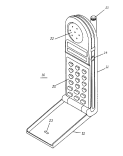
FIG. 1 is a perspective view of a communication device in
accordance with the present invention shown in the handset position.
FIG. 2 is a perspective view of the communication device shown in
the speaker-microphone position.
FIG. 3 is a side elevational view of the communication device shown
in the handset position.
FIG. 4 is an electrical block diagram of the communication device.
Detailed Iks~;~t ion of the P~f~ .~d Embo~lim~nt
Referring now by characters of reference to the drawings and first
to FIG. 1, a communication device, such as a two-way radio 10, includes a
first housing portion 11 and a second housing portion 12. In this
preferred embodiment, the housing portion 11 carries the radio circuitry
and includes a push-to-talk switch 14, volume up-and-down controls 15
and 16 (shown in FIG. 3), respectively, and carries a battery portion 17.
The radio 10 preferably further includes a keypad 20 and can
include an antenna 21 which can be either internal or external to the
housing portion 11. A speaker port or grill 22 is also located in the
housing portion 11.
The second housing portion 12 is pivotally or hingedly connected to
the housing portion 11. It includes a first or inside microphone port 23
disposed on at one of its surfaces and an outside or second microphone
port 24 disposed on another of its surfaces.
The basic electrical block diagram of the radio 10 is illustrated in
FIG. 4. As shown, the antenna 21 is coupled to receiver and transmitter
, .~,
8 7 q~ 8-
CM0094~H
portions 30 and 31, respectively, as by an antenna switch 38, Antenna
switch 38 can be an electrical switching arrangement, such as those
tili7:ing pin diodes, or can provide the antenna connection function by
serving as a circulator or duplexer where frequency division duplex radio
5 tr~n~mi~sions are to occur. Received audio si~ are supplied by
receiver 30 to an audio amplifier 32 comprising an amplifier means for
driving an audio transducer, such as speaker 33. Voice siEn~ls to be
transmitted by the radio 10 are applied to a microphone means, such as
microphone 34, from which the audio signals are amplified by a
10 microphone amplifier 35 prior to application to the transmitter 31. A
control means which can be a microprocessor, such as controller 36, is
used to control the operation of the radio 10. The push-to-talk switch 14
and up-and-down switches 15 and 16 are operatively coupled to the
controller 36 as is the keyboard 20. A position switch 37 comprising sensor
15 means, which is internal to the radio 10, is used for determining the
relative position of the housing portions 11 and 12. This position switch is
coupled to the controller 36 in order to provide automatic control features
in the radio 10 relating to the positions of the housing portions 11 and 12.
The gain of audio amplifier 32 and microphone amplifier 35 are
both controlled by the controller 36. And, preferably, are setable by using
the up-and-down controls 15 and 16. Where the controller 36 includes
internal memory, setting values can be stored within the controller 36.
Preferably, the controller 36 stores values for both the open and the closed
radio positions. For example, when the radio 10 is the open position, as
25 illustrated in FIG. 1, the gain of audio amplifier 32 and consequently, the
volume present at the speaker port 22 is set using the up-and-down button
15 and 16. When the radio 10 is in the closed position illustrated in FIG. 2,
the gain of audio amplifier 32 is set independently of the gain of the audio
amplifier when the radio 10 is in the open position. The controller 36
30 retains the last setting for the audio amplifier 32 for both positions of the radio 10. ~imil~rly, the gain of the microphone amplifier 35 is also
controlled dependent upon whether or not the radio 10 is open or closed.
The position switch 37 indicates to the controller 36 the configuration of
the radio 10. The controller 36 sets the gain of the amplifiers 32 and 35
35 accordingly.
wo 93/07680 Pcr/us92/08237
2i 187~8
-
When the radio 10 is the open or handset configuration of FIG. 1,
typically the speaker port 22 would be in relative close proximity to the
user's ear while the microphone port 23 is in relatively close proximity to
the user's mouth. In such use, the gain of audio amplifier 32 and
5 microphone ~mplifier 35 would most likely be set to relatively low values.
Alternatively, when the radio 10 is in the closed or speaker-microphone
configuration of FIG. 2, it is quite likely that the speaker port 22 would be
some distance from the user's ear. Consequently, the gain of audio
amplifier 32 would be set to a relatively higher value in order to provide
10 increased audio output from the speaker 33. If the radio 10 is to be
positioned some distance from the user's mouth, the gain of the
microphone amplifier 35 would likewise be set to a relatively higher value.
Typically, radio 10 would be used in the FIG. 2 speaker-microphone
configuration when operating in a "dispatch~ mode as is typical in a half
15 duplex radio communication system. However, when the user desires
privacy in communication or when duplex communication is to occur, the
radio portion 12 would be rotated to its handset configuration, the position
switch 37 would sense the relative positions of the housing portions and
trigger the controller 36 to adjust the gain of audio amplifier 32 and/or
ao audio microphone amplifier 35. Consequently, not only is the radio 10
usable in the two different configurations, but preferably the gain of the
amplifiers 32 and 35 are automatically controlled based upon the
configuration.
While the preferred embodiment of the communication device is the
25 radio 10, it will be understood that the communication device could be a
speaker and microphone unit which would typically be connected, as by a
cable, to a radio. Additionally, the radio 10 utilizes a single microphone 34
which communicates with both microphone ports 23 and 24. If desired,
separate microphone elements could be provided, with the position switch
30 37 operatively selecting the microphone based upon the current
configuration of the radio.
As such, the radio 10 is extremely flexible, permitting use in both
handset and speaker-microphone configurations. Preferably, the audio
level of the speaker 33 and the microphone 34 are controlled accordingly.