Note: Descriptions are shown in the official language in which they were submitted.
2113731
1 --
APPARATUS AND METHOD FOR DETECTING
TELEPHONE LINE STATUS
Technical Field
This invention relates to a method and apparatus for
5 determining when a telephone line is in use, and more particularly to a
technique that accurately determines line status in tlle face of varying line
conditions.
Back~round of the Invention
The cost of telephone sets has decreased to such a degree that
lO many, perhaps most, homes are now equipped with seYeral of them. New
homes are pre-wired for telepllones in every room an(l olrler homes are
being re-wired to strategically add telephones at Yalious Iocations. All of
this effort is aimed at improving convenience so that telephones can be
within easy reach -- no matter where individuals are located within the
15 home, whether in the basement or the bedroom. The proliferation of
telephones within the home has been encouraged by the fact that they can
all share the same wire-pair. This has led to problems v~-hen more than one
person wants to use the telephone at the same time. In particular, it is
annoying for a person already engaged in a telepllone conv. lsation to
20 endure the loud sounds tllat occur wllen another person begins dialillg.
Furthermore, there still exist sensitive persons who feel badly when they
disturb others. These concerns have been addressed by telephone sets that
visually display the status of the telephone line. Typically, a light emitting
diode associated with a telephone set is tulllerl ON whenever another
25 telephone set, that shares the same line, is in an off-hook (active) state.
However, detecting the off-hook state is not as easy as one might suspect.
Telephone Office equipment furnishes DC power to each
telephone set over the telephone line that interconnects them. ~Vhen the
telephone is in an on-hook (idle) state, there is practically no DC current
30 flow over the telephone line. When the telephone set is in the off-hook
state, there is a limited amoullt of DC current flo~r which is used to power
the telephone set and is detected by the Telel~hone Ofrlce to acti~ate
equipment to serve the telepllone set. U.S. Patent 1,1.51,707 discloses a
known design for a line status circ~lit which uses a 11~ed reference voltage to
21~87~1
- 2 -
determine whether the telephone set is in its on-hook or off-hook state.
However, the amount of DC current flow over the telepllone line is highly
variable because, for example, the length of t~le telepllone lil~e varies
considerably, so the voltage across tlle lil~e is llot tlle salne alllollg
5 telephones in the off-hook state.
Determining the appropriate on-hook/off-hook reference voltage
is ~urther complicated by the existence of low-voltage SLC ~Subscriber Loop
Carrier) lines which can have an on-hool; voltage of 12 ~olts. This is less
than the off-hook voltage or some telephones on very short telephone lines.
10 Solutions to this problem have taken one of two approaches: (1) ignore the
low-voltage SLC case since their percentage is small, or (2) provide a
customer-selectable reference voltage using a switch and a simple
installation procedure. In case (1), telephones connected to SLC lines will
always indicate that the telephone line i9 in use, tllus rendering the feature
15 useless; and in case (2), there is the added cost of the switch as well as an inconvenience to the customer who must now perform another installation
procedure which might not be performed correctly.
Additionally, it is known to sense line voltage transients to
determine when another telephone set on the same telephone line goes off-
20 hook. Such techniques, however, rely on voltage changes and can be
"fooled" by inadvertent noise as well as the operation of a pulse dialer.
Accordingly, it is desirable to determine the status of a telephone line
reliably -- regardless of its length or noise condition.
Summary of the Invention
A telephone station includes a switch for connecting it to a
telephone line, the switch causing the wire-pair to be in a first state when it
is closed and causing it to be in a second state when it is open. The
telephone station also includes apparatus for meas~ril~g the differential
voltage, VLINE, across the wire-pair. When t~e s~vitcll is closed, a first value30 of VLINE ;S measured and store~ Then ttle s~itch is opened, a second
value of VLINE ;S measured and stored. The flrst and second stored values
are used in calculating a reference voltage ~ REF tllat. resides between them
which is compared with VLINE to determine wllich olle is larger. The results
of this comparison are displayed on the telephone station.
21 18731
In an illustrative embodiment of the invention only three values of
differential line voltage are stored for each state (on-hook, off-hook). The maximum of the
three differential voltage values associated with the on-hook state is arithmeticall)~ averaged
with the maximum of the three differential voltage values associated with the off-hook state to
5 create the reference voltage.
In the illustrative embodiment, a single telephone line is shared by a number
of parallel-connected telephone sets. It is an advantage that the maximum value of the
differential voltage ll~caaulc~ is used because ~ aaUlClllcll~ are sometimes made when
another telephone set is off-hook, and this leads to erroneously low values. Finally, because
10 the reference voltage is updated each time the telephone set changes state, it readily adapts to
any set of differential voltâges on the telephone line; thereby rendering it both useful and
accurate for all telephone lines, even low-voltage S~lbscriber Loop Carrier lilles.
In accordance with one aspect of the present invention there is provided a
telephone station incl~lding a switch for connecting said telephonc station to a wire-pair used
15 for communication, the switch functioning to cause the wire-pair to be in a first state when the
switch is closed and in a second state when the switch is open, the telephone station further
including apparatus for detecting the state of a wire-pair, said apparatus comprising:
means for measuring differential voltage magnitude, VLINE, across tlle wire-pair; means for
storing a first magnitude of VLNE, whell the switch changes from being open to being closed;
20 means for measuring differential voltage magllitude7 VLINE, across the wire-pair; open to beillg
closed; means for storing a second magnitude of VLINE when the switch changes from being
closed to being open; means for averaging the first and second stored magnitudes to form a
reference voltage VREF, said reference voltage being exclusively based on measurements of the
hrst and second differential voltage magnitudes across the wire pair, but not upon any other
25 stored parameter tllat relates to the impedance condition of the wire pair; means for comparing
the magnitudes of VREF and VLINE to determine whicll olle is larger; and means for indicatillg
tlle results of said comparison.
11l accordance with another aspect of the present inventioll there is provided
a method for detecting the status of a telephone line ~Ising an interconnected telephone set
30 having an ACTIVE state and an IDLE state, the ACTIVE state causing a first differential
voltage to be prcscllt oll tlle telephone line and the IDLE state causillg a second diffcrelltial
voltage to be present on the telephone line, the method comprising tlle steps of: measuring tlle
first differelltial voltage when the state of the telephone set changes froln the IDLE to tlle
ACTIVE state; meas~lring the second differential voltage when the state of the telephone set
A
21 18731
-3a-
changes from the ACTIVE to the IDLE state; selecting a reference Yoltage between the first
and second differential voltages, said reference voltage being selected exclusively based on
UICIIICIII~ of the first and second differential voltage magnitudes across the wire pair, but
not upon any other stored parameter that relates to the impedance condition of the wire pair;
5 measuring a differential voltage, VLINE, on the telephone line; comparing VL~NE with the
magnitude of the reference voltage to determine which one is larger; and displaying the results
of the comparison.
BRIEF DESCRIPTION OF THE DRAWING
The invention and its mode of operation will be more clearly understood
10 from the following detailed description when read with the appended drawing in which:
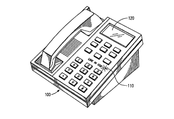
FIG. I discloses a telephone set equipped with displays for indicating line
status;
FIG. 2 discloses a high-level block diagram of circuitry for detecting line
status in accordance with the invention;
FIG. 3 is a detailed schematic drawing of the line status detector of the
present invention; and
FIG. 4 shows a flow diagram used in implementing the invention.
DETAILED DESCRIPTION
FIG. I shows a high-feature telephone set 100 that includes a liquid crystal
20 display (LCD 120) which provides a good deal of information to users such as time-of-day,
dialed telephone numbers, or even the telephone number of an incoming call. A telephone
line (not shown) connects telephone set 100, along with any other telephone sets that share the
line, to a Telephone Office. The present invention is concerned with detecting when those
other telephone sets are off-hook and displaying such information on telephone set 100.
25 Accordingly, LCD ~ 20 may be used for
2~ ~8731
- 4 -
this purpose along with the display of the other information discussed
above. Because LCDs generally rely on reflected light, they do not
command the attention of users and are, therefore, not widely used for
displaying line status. Instead, a light emitting diode such as LED 110 is
5 used to alert a user that the telephone line is in use. Genelally, LED 110 is
turned ON when the line is in use, and turne-l OFF when the line is
available.
A high-level block diagram is shown in FIG. 2, which generally
illustrates the major functional components used in implementing tl1e
10 present invention. A high impedance amplirler 200 is used to bridge (a
parallel electrical connection) the line statlls detectil1g circuit onto the Tip-
Ring leads of the telephone line. A high impedance connection is used to
minimize current drain during the on-hook state in order to meet regulatory
requirements. It is noted that the telephone line itself n1ay include leakage
15 paths to ground along the route from the Telephone Ofrlce, which also
contributes to the current drain. The output of the high impedance
amplifier includes a DC voltage that is representative of the voltage
difference between the Tip-Ring input terminals. A precision rectifler and
low-pass filter 300 assures that the DC voltage has the same polarity when
20 the Tip-Ring connection is reversed, alld that Doise tr~nsients and speech
signals are removed from the resultillg DC voltage.
At this point, the DC voltage is converted into a digital signal by
analog-to-digital (A/D) converter 410 for use in microprocessor 420. The
present invention takes advantage of the fact that a microl~rocessor is
25 present and is seldom used to its full capacity when tlle telephone set is in the on-hook state. Even the simplest telephone sets now use
microprocessors because of their ability to perform so many different tasks
and their low cost.
A detailed schematic of tlle block diaglam of FIG. 2 is disclosed
30 in FIG. 3, which shows the line status circuit parallel-connected to the input
circuitry of the telephone set. The input circuitry is shown because it is
representative of the circuitry within the other telephone sets that connect
to the same Tip-Ring terminals. Fuse 130 limits the maximum current that
can be drawn by the telephone set in order to protect against excessive
35 heating during a fault condition. ~letal Oxide Varistor 110 protects the
telephone set against over~oltage and lightning con~litions, and
5 211g73
transformer 160 provides DC isolation between the telephone line and
circuitry within the telephone set. Of particular interest is lille switch 150
which may be a metallic contact ol a semiconductor device. In either event,
the cumulative DC resistance of the input circuitry presented to the Tip-
5 Ring terminals is typically 150-200 ohms when the line switch 150 is closed
(off-hook state). In the present invention, line switch 150 is a solid state
device which is commercially available rrom AT&T as Part Number LH-
1056AT. It has a typical DC resistance of 30 ohms, and the typical DC
resistance of the transformer 160 is 120 ohms. Other telephone sets that
10 share the telephone line are assumed to have similar DC characteristics.
Amplifler 200 is parallel connected to Tip-Ring terminals and
includes input resistors 210, 230 which are 22M-ohms each to assure high
input impedance. Bias resistor 240 and feedback resistor 220 are selected to
be lM-ohm each. Differential amplif~er 250 cooperates with resistors to
15 provide a gain of approximately -0.05. For example, if tlie Tip-to-Ring
voltage is -30 volts, then the output voltage of difrerential an1plirler 250 is
+1.36 volts; and if the Tip-to-Ring voltage is +30 volts, then the output
voltage of differential amplir~er 250 is -1.36 volts Because this voltage can
be positive or negative (when the Tip-Ring terminals are reversed) a
20 precision rectifler is used to provide a single polarity output signal.
Diodes 315, 316 are connected to provide feedback in differential
amplifier 310 so that when the input voltage to amplifier 310 is positive, the
amplirler provides a gain of -1.0 because resistors 312 and 313 are equal; but
when the input voltage to amplifler 310 is negative. the voltage at the
25 junction of resistors 313, 314 remains at zero volts (due to the signirlcant
feedback through diode 316 from the output of amplirler 310 to its input).
Accordingly, amplirler 310 operates as an inverting half-wave rectirler when
the input voltage is positive. The extension to a full-wave rectifler is
effected by amplifier 320 ~hose input is delivered via resistor 311 when the
30 input voltage is negative. Amplirler 3~0 is extended l~ tlle a~ldition of
capacitor 321 to become a first order low-pass filter. Further detail
regarding the construction of precision rectifier and lo-v-pass filter 300 can
be found in Advanced ~ectro71ic circlLit~ by ~r. Tietze an~l C. Schenk, pp.
449-452, ~ 1~8 Springer-Verlag Berlin Heidelberg. An illustrative example
35 of a commercially available operational amplirier which is suitable for use in
the present invention is Part No. TI,C2~f 1RC'D from Texas Instruments.
-6- 2~18731
Having rectifled and filtered the differentiai voltage across the
Tip-Ring terminals of the telepllone line. tlle ~esulting signal is then
converted into a binary digital number by A/D converter 410, and processed
in microprocessor 4~0 according to steps in the flow diagram of FIG. 4. A
5 suitable microprocessor which has built-in ~/D conversion is Part No.
M37700 -- a 16-bit microprocessor which is commercially available from
Mitsubishi.
Referring now to FIG. 4, the invention will be described with
greater particularity. Briefiy, however, the present invention discloses a
10 telephone set that "learns" the meanil~g of different voltage differentials
across the telephone line VLINE and then decides whether the voltage
differential represents a line-in-use condition. This is accomplished by
measurements taken each time the telephone set goes on-hook or off-hook.
The measurements are averaged to create a reference voltage VREF which is
15 continuously compared with VLINE to determine wl~ether any telephone set
is using the telephone line. This procedure assumes that all telephone sets
have approximately the same DC input resistance and, thus, create the
same differential line voltage when they are in the off-hook state.
The differential line voltage VLINE ;S contilluously monitored
20 and compared with the reference voltage VREF- Wllen VREF > VLINE~
then Ll~D 110 (see FIG. 1) is turned on, otherwise it is turned off. FIG. 4
illustratively shows how VREF ;S determined. The process begins when the
switchhook changes state and is substantially the same regardless of
whether it changes to the on-hook state or to the off-hook state. In the
25 situation wherein the switchllook changes to the off-hook state a first
counter is advanced, and this is denoted by the operation set j = j+1. The
differential line voltage VLINE is then stored as ~'OFF- HOO~; (j). Since only
the most recent values are stored (3 in the illustrative embodiment),
VOFF- HOOK (j--3) is discarded. The n1axin111m vallle of the 3 most recent
30 measurements is designated MAX VOFF- HOOI~ and is used in caiculating
V REF -
In the situation wherein the switchhook changes to the on-hook
state a second counter is advanced, and this is denoted by the operation set
k = k+1. The differential line voltage VLINE is then stored as
35 VON- HOOK (k). Since only the most recent values are stored (3 in the
illustrative embodiment), VON - HOOK ( k--3 ) is discarded. The maximum
7 21~8731
value of the 3 most recent m~ mcnts is designated ~Y VON- HOOK
and is used in calculating VREF
VREF is then calculated as the arithmetic average of MA,Y
VOFF- HOOK and MA~Y VON- HOOli, and used to determine whether
5 another telephone set on that same telephone line is usillg it. It is noted
that VREF is re-calculated each tilne the telepholle set changes switchhook
state. Precision rectirler 300 (see FIG. 3) assules tllat all voltage quantitieswill be of the same polarity (positive) so that the invention will still function
properly if a Tip-Ring reversal occurs. T~le following discussion relates to
10 the reason for using maximum values in calculating ~REF
Consider the situation whereby two telephone sets are off-hook
at the same time (e.g., two persons at the same residence are using different
telephones to talk to grandma), and the one which uses the invention is
returned to its on-hook state. The measured differential line voltage,
15 VLINE, will be improperly low because the other ~elepholle set is still off-
hook. If repeated, this situation will lead to improperly low values for
VON- HOOK (k) and, possibly, to an improperly low value for VREF. SinceMA~YVoN_HooK(k) is used rather than MIN VoN_HooK(k)~ it would
take 3 consecutive repetitions of this situation to cause an error in VREF
20 Accordingly, it is advantageous to use the maximum value of
VON--HOOK (k) in calculating VREF
Similarly, consider the situa~ion ~lhereby one telephone set is
already off-hook and the one wllich uses the invention goes off-hook (e.g.,
one family member is asked to pick up the telephone to talk to gl~andma).
25 The measured differential line voltage, VLINE, W;ll be improperly low
because the other telephone set is off-hook. If repeated, this situation will
lead to improperly low values for VOFF- I~ ) and, po.ssibly, to an
improperly low value for VREF. Since MA~Y VOFF- HOOK(;) ;S used rather
than MIN VOFF - HOOK (i ), it would take 3 consecutive repetitions of this
30 situation to cause an error in VREF. Accordingly, it is advantageous to use
the maximum value of VOFF - HOOK (i ) in calculating VREF
Although a particular embodiment has been shown and
described, it is understood that various modifications may be made within
the spirit and scope of the invention. These modifications include, but are
35 not limited to, the use of more (or less) than three measl1rements in
determining MA,Y VON- HOO~ and/or M~Y VOFF- HOOK; the use of other
-8- 211~73~
than maximum values of these voltages; the calculatioll of a value for VREF
using non-linear, or geometl ic, or difrerently weighted combinations of
VON_ HOOK and VOFF_ HOOK voltages; and the use of audible, rather than
visual, line status indicators. It is noted that all transitions between off-
5 hook and on-hook states need not be accompanied by a recalculation of
VREF, For example, when the invention is used in a telephone answering
machine, a feature known as remote hold release causes the ansWerinB
machine to hang up when another telephone set goes off-hook. In this
situation, the differential line voltage is not appropriate to use for updating
10 VREF