Note: Descriptions are shown in the official language in which they were submitted.
~l 2118868 LAYERED TUBE WITH CONTROLLED FLEXIBILITY
; ~
This invention relates to tubes and ho~es with controlled
flexlbility, especially -- but not exclusively -- for use in
,J~ the automotive industry, and more particularly to lightweighttubes and hoses which are highly resistant to chemical
degradation or an electrical charge accumulation.
Reference is made to UOS~ Patent No. 3,16~,688 for a
description of polytetrafluoroethylene having electrical
conductive characteristics, which is especially useful in
draining away static electrical charges. The teachings of this
patent may be used in the inventive hose, although many
different fluorocarbon plastic materials may be used.
Hoses of the described type are subject to degradation
from the chemicals which they convey, to an accumulation of
v electrical charges responsive to an internal fluid flow, and to
,!, 15 kinking and other bending deformations. Also, on automotive
. vehicles, they often encounter vibration, swinging, and
whipping. The invention is designed not only to overcome these
and similar problems, but also to provide principles which have
application to hoses used in many other areas.
When problems of this type have been solved in the past by
,~,.j
providing multilayer hoses, a common trouble has related to a
i difficulty in getting the various kinds of materials to bond or
i otherwise be joined together and in preventing them from
delaminating. In a multilayer hose of the described type, the
outer jacket could work its way off the inner or core layer
,}~ unless the two layers are somehow constrained. These problems result from the chemical inertness of the materials lining the
hoses and from the differences in the relative weights of the
~,
materials.
Beyond these problems, a desire is to ma~e a mechanically
y strong hose, which is as light as possible, considering the job
which it is to do. One problem with PTFE is that it often has
~.,,
.~ .
,~
,'., ,. ' ~ :
Z~ 68
little strength on a "pull" test, often less than 10-pounds
when a "pull" strength in the order of perhaps 100-pounds is
desired. This is important to meet Federal vehicle safety
standards. Different hoses may require dif~erent degrees of
flexibility or even one degree of flexibility when bent in one
manner and other degree of flexibility when bent in another
manner.
The need for mechanical strength also re~uire~ an outer
jacket which resists abrasion. When flexibility becomes too
great the hose is given to kinking; therefore, another goal is
to provide a hose which is highly flexible without
simultaneously kinking and bending. Still another object is to
prevent obstructions to internal fluid flow, such as may occur
in convoluted hoses that are often used in these described
conditions.
Accordingly, an object of the invention is to provide new
and improved hoses of the descri~ed type, especially for
automotive purposes. Here, an object of the invention is to
provide a hose having an internal fluorocarbon polymer,
corrosion resistant liner surrounded by a relatively thick
outer jacket or layer of suitable elastomeric or plastic
material. In this connection, an object is to provide a good
mechanical joining between the internal liner and the outer
jacket.
Another object of the invention is to provide an
electrically conductive inner liner to carry away electrical
; charges that may be generated by the internal fluid flow.
In keeping with an aspect of the invention, these and
other objects are accomplished by an extruded fluorocarbon
.~
! 30 inner hose liner with preferably circumferential grooves on lts
exterior wall. ~hese grooves may be either continuous or
intermittent around the circumference. The grooves receive and
., ¦
'
i ~
21~88~8
~hanically interlock with plastic or other elastomeric
materials used to make an outer jacket. The pre~erably
circumferential annular grooves on the inner liner are spaced
from each other by a dlstance or distances selected not only
, 5 for the mechanical lnterlocking of the layers, but also fox the
3~ degree of flexibility requirements of the hose. The focus of
,~ the invention is primarily upon these grooves on the inner
'~ liner and the mechanical locking which they provide between the
liner and the jacket.
A preferred embodiment of the invention is shown in the
1 attached drawings, in which:
,5~ FIG. 1 is a fragmentary showing of a circumferential cross
section of the inventive hose;
FIG. 2 is a perspective view of a hose with the outer
jacket broken away to show the construction of the grooved
liner;
~31 FIG. 3 is a longitudinal cross sectional showing of the
inventive hose;
FIG. 4 is another perspective view with the outer hose
jacket partially broken away in order to show the construction
of a hose having different degrees of flexibility distributed
along the length thereof; and
FIGS. 5A - 5E show alternative cross sections for the
locking groove which provide different flexibility to the
inventive hose.
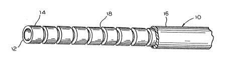
The inventive hose 10 (FIG. 1) has an electrically
conductive inside layer 12, an extruded inner liner 14, and an
extruded outer layer or jacket 16. All three layers 12, 14 and
16 are made of plastic or elastomeric material such as
fluorocarbon. When the outer layer is made of PTFE, it may
have a thickness in the order of 0.25 to 1.5 mm, with a
preferred range of 0.4 - 0.9 mm. ~f the outer jacket is made
. ~
'
.
~i 1 211~86~
:
Nylon, the thickness may be in the ranye of 0.020 - 1.00 mm.
A dashed line 18 indicates the bottom of grooves that axe
; formed in the inner liner 14.
The electrical liner 12 may be made according to the
teachings of U.S. Patent No. 3,166,688. Since all three of the
layers 12, 14, 16 are preferably made of the same kind of
material (e.g. a fluorocarbon), they are compatible so that
they may be chemically bonded to each other. However, the
invention does not normally require any adhesive or bonding
between layers.
. FIG. 2 shows the mechanical construction of the inventive
hose 10. The liner 14 is extruded and formed with annular or
,~ circumferential grooves 18 distributed along the length
thereof. These grooves may be either continuous or
intermittent around the circumference of the hose. Generally,
the grooves are uniformly distributed along the length of the
tube because most hoses should have a uniform flexibility
:~ throughout. However, it is also within the scope of the
invention to have the grooves closer to each other in some
areas and further apart in other a~eas. As the grooves are
3 located closer together, the hose becomes more flexible. Asthe grooves are located further apart, the hose becomes less
flexible.
There are some hoses which should be relatively stiff
near their ends and relatively flexible away from their ends;
therefore, as shown in FIG. 4, the groov~s at 22 could be
:¦ relatively far apart near the end and relatively close together
~ at a location which is away from the ends so that stress relief
;;~ is provided at or near the end fittings. An example of such a
hose is one (such as a brake fluid line) which whips about as
the vehicle is in motion.
.
,''~
' ~! ,......
2~8~ ~
A grooved hose of the described type might be especially
subject to kinking at the grooves. Therefore, it is desirable
to provide an outer jacket or layer which fills the grooves and
resists kinking. The outer jacket or layer 16 may be made as
thick or as thin as necessary in order to make the hose strong
enough to perform any desired function. However, for mos~
automotive uses, a preferred range of outer jacket or layer
thickness is approximately .25 mm to 1.5 mm. Also, the
particular material used for the outer jacket is selected on a
basis of such things as abrasion resistance, immunity to
environmental hazards, and the like. Other thicknesses and
~- materials may be used on hoses for other applications.
The method of manufacturer is to first extrude the inner
liner 18, complete with the internal electrically conductive
i 15 inner layer 12. In another manufacturing step, the grooves 18
~ are formed by either a material removal or displacement with
'f either a uniform or a random spacing or with a combination of
uniform and random spacing. At its end, the spacing between
the hose grooves depends somewhat upon the length of the end
fit~ing or the end stresses. A third manufacturing step causes
the inner hose 14 to move through an extruder so that the
fluorocarbon outer layer 16 material completely fills the
grooves to form a mechanical connection or bonding between
layers 14, 16.
The temperature and pressure process parameters depend
upon the specific materials that are selected; however, in
general the processing temperature for extruding the outer
jacket 16 is lower than the temperature for extruding the liner
14.
All layers are preferably made of fluorocarbon so that a
non-mechanical (e.g. purely chemical) bonding would probably
fail, either at the time of manufacture or later during
~, '
,, ~. , . . .: - . .
;~ 2~18~8
i:
~eration. Or, in the alternative, if a chemical or similar
bonding could be achieved in some cases, the process would
~i likely be very costly.
The advantage of the grooves, as compared to other surface
irregularities is that the annular groove~ may be shaped and
spaced to achieve desired results, especially in the area
requiring kink resistance. Another advantage of the use of
grooves is that there is a corrugated outer wall and a smooth
inner wall giving the desirable features of a convoluted hose
without the disadvantages of internal flow interruptions and
turbulence resulting from the internal convolutions.
FIG. 4 shows the inventive hose and FIG. 3 is an enlarged
showing of a portion of FIG. 4. The grooves are identi~ied as
having a rectangular cross section having a width "X" and a
~`i
depth "Y". In a preferred embodiment, the "X" or width
dimension is .13 mm to .7 mm and the "Y" or depth dlmension is
.13 mm to 1.0 mm. The inner groove spacing "Z" is determined
empirically for each hose type depending upon the desired
i: degree of flexibilityO
~ 20 The grooves may be given special cross sectional shapes to
.~ provide special effects. For example, FIG. 5A shows a
rectangular groove which gives a uniform response regardless of
the manner in which the hose is bent. In FIG. 5B, the groove
has a triangular cross section so that the inner and outer
jackets normally rest in a predetermined position. As the hose
bends, the triangular tooth on the outer jacket has to climb up
the inclined side oE the triangular groove, thereby introducing
l a resistance to bending which becomes progressively greater as
the radius of hose bendlng increases. In FIG. 5C, the groove
has a rectangular cross section with a triangle at the root of
".,
the groove, to give an effect which is a combination of the
; effects of FIGS. 5A, 5B. In FIG. 5D, the groove has a mortise
. .
:!
,',.,~ '
~.~
2 1 ~
a dovetail joint, whlch should make the hose most resistant
to bending. In FIG. 5E, the groove has a cross section of a
right triangle. When the bending of the hose presses together
the perpendicular walls of the outer jacket tooth and inner
liner groove, there is a resistance to bending. When the
inclined planes of tooth and groove bear against each other,
there is a progressively greater reslstance to bendingO
Those who are skilled in the art will readily perceive
many modifications which may be made to the described
)
1 10 structure. Therefore, the appended claims are to be construed
to cover all equivalent structures falling within the scope and
3 the spirit of the invention.
P!
'.:.1, ', ~ '
!,1 3 :: ~
~!
~!
~.,
'
i', .