Language selection

Search

Patent 2119106 Summary

Third-party information liability

Some of the information on this Web page has been provided by external sources. The Government of Canada is not responsible for the accuracy, reliability or currency of the information supplied by external sources. Users wishing to rely upon this information should consult directly with the source of the information. Content provided by external sources is not subject to official languages, privacy and accessibility requirements.

Claims and Abstract availability

Any discrepancies in the text and image of the Claims and Abstract are due to differing posting times. Text of the Claims and Abstract are posted:

  • At the time the application is open to public inspection;
  • At the time of issue of the patent (grant).
(12) Patent: (11) CA 2119106
(54) English Title: ASYMMETRIC PULVERIZER TIRE
(54) French Title: PNEU ASYMETRIQUE POUR PULVERISATEUR
Status: Expired
Bibliographic Data
(51) International Patent Classification (IPC):
  • B02C 4/30 (2006.01)
  • B02C 15/00 (2006.01)
(72) Inventors :
  • HAND, BRYAN (United States of America)
  • MIZAK, RONALD D. (United States of America)
  • PIEPHO, ROBERT R. (United States of America)
(73) Owners :
  • THE BABCOCK & WILCOX COMPANY (United States of America)
(71) Applicants :
(74) Agent: RIDOUT & MAYBEE LLP
(74) Associate agent:
(45) Issued: 1998-06-16
(22) Filed Date: 1994-03-15
(41) Open to Public Inspection: 1994-09-17
Examination requested: 1994-03-15
Availability of licence: N/A
(25) Language of filing: English

Patent Cooperation Treaty (PCT): No

(30) Application Priority Data:
Application No. Country/Territory Date
08/033,694 United States of America 1993-03-16

Abstracts

English Abstract


Reinforcement sections are provided at an outer surface and
at an inner surface of a tire for a roll wheel assembly used in
a pulverizer for crushing a material such as coal. These
reinforcing sections cause the tire to be asymmetrical and are
located on the tire only at areas where the wearing of the tire
is highly predictable. The reinforcing sections provided on the
inner surfaces of the tire are provided directly opposite of the
reinforcing sections on the outer surface for preventing the
localized thinning of the tire and extending the time interval
between rotation and/or replacement of the tires.


French Abstract

Sections de renfort aux surfaces extérieures et intérieures d'un pneu pour une roue utilisée dans un pulvérisateur servant à broyer un matériau comme le charbon. Ces sections de renfort confèrent une forme asymétrique au pneu et elles ne se trouvent sur ce dernier que dans les points où l'usure du pneu est très prévisible. Les sections de renfort sur les surfaces intérieures du pneu se trouvent directement à l'opposé des sections de renfort de la surface extérieure afin d'empêcher l'amincissement localisé du pneu et de prolonger l'intervalle entre les rotations ou le remplacement des pneus.

Claims

Note: Claims are shown in the official language in which they were submitted.


- 7 -


THE EMBODIMENTS OF THE INVENTION IN WHICH AN EXCLUSIVE
PROPERTY OR PRIVILEGE IS CLAIMED ARE DEFINED AS FOLLOWS:

1. A tire for a roll wheel assembly used to crush
material in a pulverizer, the tire having an outer surface for
contacting and crushing the material, the tire comprising:
a first reinforcing section fixed to the outer surface of
the tire at a location where the tire is subjected to wearing
due to performing the crushing of the material; and
a second reinforcing section fixed to an inner surface of
the tire directly opposite of the location where the tire is
subjected to wearing for minimizing localized thinning of the
tire.

2. The tire according to Claim 1, wherein the reinforcing
sections are at areas where the tire wearing is predictable.

3. The tire according to Claim 1, wherein the tire is
made of an alloy.

4. The tire according to Claim 3, wherein the reinforcing
sections are made of the same alloy as the tire.

5. The tire according to Claim 1, wherein the reinforcing
sections are made of a different material than that of the tire.

6. A method for prolonging the use of a tire of a roll
wheel assembly for a pulverizer used for contacting and crushing
a material, the method comprising:

- 8 -
providing a reinforcing section on an outer surface of the
tire at a location where the tire is subjected to wearing due to
performing the crushing of the material; and
providing a reinforcing section on an inner surface of the
tire directly opposite of the location where the tire is
subjected to wearing for minimizing localized thinning of the
tire.

7. The method according to Claim 6, wherein the
reinforcing section is created by adding at areas on the tire
where the tire wearing is predictable.

8. The method according to Claim 6, wherein the thickness
of the tire is increased 30% after providing the reinforcing
material on the tire.

9. The method according to Claim 8, wherein the weight of
the tire is increased not more than 10% after providing the
reinforcing material on the tire.

10. The method according to Claim 6, wherein the
reinforcing sections are created by affixing additional material
by means of weld deposition to an existing tire.

11. The method of claim 6, wherein the reinforcing
sections are created by casting them as part of the tire in an
as-cast configuration.

12. The method of Claim 6, wherein the reinforcing
sections are preformed reinforcement sections placed in a
casting mold prior to providing molten metal forming the balance
of the tire to composite casting them into the tire.

- 9 -

13. The method of Claim 6, wherein the reinforcing
sections are made as separate elements which are later
mechanically affixed via fasteners or the like to an existing
tire.

14. The method of Claim 6, wherein the reinforcing
sections are created by sleeving them over and into an existing
tire.

Description

Note: Descriptions are shown in the official language in which they were submitted.


-~ CASE 5315 ; 2~191~ ~


,................................................................. .


AS~lbl~.l'~TC PULVF~12T7~ TIRE ~:


FIEID AND P1~ n~ U~V OF TBE 1NV~1ON
The present invention relates. in general to grin~i n~
elements ~or pulverizers and in particular to a new and useful
design for a tire used in a roll wheel assembly for a pulverizer
which increases the wear life of the tire.
Pulverizers are commonly used to grind various materials in
the coal processing, ceramic, and chemical industries. A roll
and race pulverizer uses grinding elements comprising a
plurality of roll wheel assemblies or tires susp~e~ from
driving arms and which rotate around their respective axes of
rotation th~ou~l- contact against a grin~i~g ring or race for
grin~i ng and r~uci ng the size of the incoming material,
part~¢~ rly coal. Each grln~ng element or roll wheel assembly
uses a replaceable outer tire. Currently, the replAc~hle outer
tires used in the roll wheel assemblies are manu~a~Led from
alloy as a casting and are symmetrical about a radial center
plane.
Despite the symmetrical orientation o~ the replA~eA~ble
outer tires of the roll wheel assemblies, the tires wear
unevenly during normal pulverizer operation. The problem with
uneven wear can be resolved by rotation; i.e., a side-to side


- .,. . :. ~. .,. .. ~........ ,. , ..... : .. .
.
::,: : ~ ,
. ,
-. . , - . :.

' QSE 5315 ' 211 910~

-- 2 --
reversal of the partly worn tire comprising each roll wheel
assembly. However, to perform this operation the pulverizer has
to be stopped and taken out of service for a significant period
of time. The task of pulverizer tire rotation requires l' vdl
of the entire roll wheel assembly from the pulverizer through an
access door. This is a difficult and labor intensive operation;
special equipment is required because each roll assembly can
weigh as much as 3~,000 pounds. Once removed from the
pulverizer, the tires must be ~isA~sembled from the roll wheel
Acs~ lies by performing a heating operation. This raises the
possibility of local overheating and resultant cracking, which
will ruin the tire and require it to be repaired, if possible,
or replaced. Additionally, only a slight improvement in useful
tire life is achieved through this tire rotation ~-oce~ e, and
it is generally not Pnough to justify the costs involved
Thus a need exists for an imp,Gved pulverizer tire for a
roll wheel assembly that can provide increased wear life at
minimal addit~onal cost.

S~DY OF T~E INVL...10N
The present invention comprises a replaceable outer tire
fo,r" a roll wheel assembly having a reinforcing section at the
outer ~urface of the tire for contacting and cr~ching the
material. A oecon~ reinforcing section is provided on an inner
~urface of the tire directly opposite of the reinforcing section
2S on the outer surface of the tire for minimizing wearing of the
tire.
The reinforcing sections can be made of a ~einforcing
material which is located at the outer surface and the inner
surrace of the tire where the tire i5 most li~ely subjected to
normal wear. The reinforcing sections minimize localized thin
~pots which can occur during normal wear or the tire.
The various feature~ of novelty which characterize the
invention are pointed out with particularity in thè claims
A}~n~Ye~ to and forming a part of this disclosure. For a better


, ~ ;-: . , , ,.:


,

.

~ CASE 5315 211910 ~ ~3
~ .
-- 3
understanding of the invention, its operating advantages and
specific benefits attained by its uses, reference is made to the
a-- anying drawi~gs and descriptive matter in which a
preferred embodiment of the invention is illustrated.

S BRIEF ~CCRTPTION OF T~E DP~-ITNGS
~.
In the drawings:
Fig. 1 is a perspective view of a pulverizer;
Fig. 2 is a cross-sectional view of a roll wheel assembly of
the pulverizer of Fig. l;
Fig. 3 is a SÇh~- - tic representation of the gri~ element
profiles of a tire for the roll wheel assembly of Fig.
2 showing how they wear from initial profile to end of
useful life;
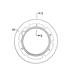
Fig. 4 i8 an elevational side view of a tire according the
present invention; and
Fig. 5 is a cross-sectional view taken along line 5-5 of the
tire of Fig. 4;

DESCRIPTION OF TEE Ph~LKK~v EMBODIMENTS
Referring to the Figures generally, wherein like numerals
ZO ~es~nAte the same element thLvuJlou~ the several drawings, Fig.
1 show~ a ~eL~pective view of a pulverizer generally designated
10, for gr~nA~ng inco~ing material such as coal. The grinA;n~
or crushing of coal in the pulverizer 10 is co~ Led wi~hin a
pulverizer housing 12. The pulverizer housing ~2 contains a
plurality of roll wheel assemblies 14, typically three in
number, which are pressed ag~infit a gri~ing ring 16 by a spring
loi~A~ system 18. The gri~ing ring 16 rotates about a
vertical axis of the pulverizer 10, and each of the plurality of
roll wheel assemblies 14 has a repli~sqAhle outer grlndi ng
element or tire 20 mounted for rotation thereon. Each tire 20
rotates around its ~espeiiLive axis of rotation through contact
~,


, -.: . : -~: .
: . . .
:.:. . ,....... ........ ~ :
.. . .. . .. : . .. :
: ~ .... .
,., ~ . , . : .


. .,, ", . . . " .... . ,.. ; ~, ,. , ,, . ,.~,~.. .. .. . .

~ QSE 5315 i 211910 ~

-- 4
against the grinding ring 1~, the incoming material being
crushed therebetween.
Referring to Fig. 2, each roll wheel assembly 14 comprises
the replaceable outer grin~in~ element or tire 20 supported on
a tire s~rport 22 rotatably mounted about an axle 24 of the roll
wheel assembly 14. Each roll wheel assembly 14 uses a roll pin
block 26 and a roller bracket 28 to allow the tire 20 to rotate
about its axis as the gri n~ i nq ring 16 rotates within the
pulverizer 10. A roll air seal 30 is provided for sealing coal
lo and other abrasive particles out of the roll wheel assembly 14.
Fig. 3 illustrates the design of tires 20 commonly used in
pulverizers 10. It will be observèd that the tires 20 commonly
used in these pulverizers 10 have an inner section 32 and a wear
zone 34 which contacts the material lying within the grin~i ng
~5 ring 16. The tires are commonly made of a highly abrasion
resistant material such as one of the white irons specified in
ASTM A 532. During normal use, the tire 20 is r~duce~ in size
becA~-~e of the abrasive p~ope~ies of the material being ~Lo~.d,
the tire 20 wearing at the wear zone 34 which results in a
thinning of the tire 20.
Referring now to Figs. 4-5, there is shown the present
invention. As shown therein, the present invention comprises
the tire 20 having a reinforcement section 36 located at the
wear zone 34. A reinforcement section 38 is also provided at
the inner ~ection 32 of the tire 20 directly opposite the wear
zone 34 for ~e~el.~ing 1OC~A1jZQI~ th~n~in~ of the tire 20 as it
wears during pulverizer operation. The reinforcement sections
36 and 38 are preferably made of the same material or alloy as
that Or the ~AlAnce of the tire 20, or it can be made of a
different wear resistant material to further enh~nce the wear
life of the tire 20. The reinforcing ~ections 36 and 38 may be
affixed to an eXisting tire 20 by means of weld deposition
methods, or it can be part of the tire in an as-cast
configuration. Compos~te casting methods i.e., wherein
preformed reinforcement sections are placed in the casting mold

CASE 5315 2il910G ~s
,


prior to pouring the molten metal forminq the balance of the
tire, can also be employed to produce a tire 20 with the
reinforcing sections 36 and 38. Alternatively, the reinforcing
sections 36 and 38 could be made as separate elements which are
s then later ~chA~ically affixed via fasteners or the like to an
existing tire 20. Finally, yet another approach to creating a
tire 20 with the reinforcing sections 36 and 38 is add them by
sleeving them over and into an existing tire 20.
The present invention thus provides for a tire 20 having an
asymmetrical outside diameter surface which results in improved
wear life with only a minor increase in maximum section
thi~ ss. An immediate benefit is that the time interval
~e~ween pulverizer tire 20 rotation and/or replacement is
increased.
In lieu of the aforementioned asymmetrical outside diameter
surfa¢e, a larger symmetrical outside diameter surface could be
added. However, this would be a costly and inefficient use of
costly alloy material. In lieu of an inside surface that
ap~Loximates the outside wear configuration, a tire 20 could be
de,s~gned with a symmetrical inside surface having an equivalent
minimum thi~n~ss or with a solid alloy core. Howe~a~, once
again this would not be an efficient use of this costly alloy
material. In addition, a massive increase in section thi~nDss
greatly increases the difficulty of achieving reliably sound
castings and att~n~-nt increases in reject rates for these
casting~ and associated costs.
Reinforcement sections 36 and 38 are provided on the tire
only at predictable high wear areas, resulting in an
a~oximately 30% increase in tire 20 wear mater~al th;~-.rss,
with only an approximately 10% increase in overall tire 20
weight.
While specific embodiments of the invention have been shown
and described in de~ail to illustrate the application of the
principles of the invention, it will be understood that the


.,....... ... . - - .. ~ ~ :

~, . - ~,. . .. .


' ' . . : ' , ' . '' ' ' ':
,
.. .. . . . . ...

' -~ CASE 5315 211~10~

-- 6 --
invention may be embodied otherwise without departing from such
principles.

Representative Drawing
A single figure which represents the drawing illustrating the invention.
Administrative Status

For a clearer understanding of the status of the application/patent presented on this page, the site Disclaimer , as well as the definitions for Patent , Administrative Status , Maintenance Fee  and Payment History  should be consulted.

Administrative Status

Title Date
Forecasted Issue Date 1998-06-16
(22) Filed 1994-03-15
Examination Requested 1994-03-15
(41) Open to Public Inspection 1994-09-17
(45) Issued 1998-06-16
Expired 2014-03-17

Abandonment History

There is no abandonment history.

Payment History

Fee Type Anniversary Year Due Date Amount Paid Paid Date
Application Fee $0.00 1994-03-15
Registration of a document - section 124 $0.00 1994-08-26
Maintenance Fee - Application - New Act 2 1996-03-15 $100.00 1996-02-28
Maintenance Fee - Application - New Act 3 1997-03-17 $100.00 1997-02-24
Final Fee $300.00 1998-01-19
Maintenance Fee - Application - New Act 4 1998-03-16 $100.00 1998-02-27
Maintenance Fee - Patent - New Act 5 1999-03-15 $150.00 1999-03-03
Maintenance Fee - Patent - New Act 6 2000-03-15 $150.00 2000-02-18
Maintenance Fee - Patent - New Act 7 2001-03-15 $150.00 2001-02-20
Maintenance Fee - Patent - New Act 8 2002-03-15 $150.00 2002-02-21
Maintenance Fee - Patent - New Act 9 2003-03-17 $150.00 2003-02-24
Maintenance Fee - Patent - New Act 10 2004-03-15 $250.00 2004-02-20
Maintenance Fee - Patent - New Act 11 2005-03-15 $250.00 2005-02-21
Maintenance Fee - Patent - New Act 12 2006-03-15 $250.00 2006-02-17
Maintenance Fee - Patent - New Act 13 2007-03-15 $250.00 2007-02-19
Maintenance Fee - Patent - New Act 14 2008-03-17 $250.00 2008-02-18
Maintenance Fee - Patent - New Act 15 2009-03-16 $450.00 2009-02-17
Maintenance Fee - Patent - New Act 16 2010-03-15 $450.00 2010-02-18
Maintenance Fee - Patent - New Act 17 2011-03-15 $450.00 2011-02-17
Maintenance Fee - Patent - New Act 18 2012-03-15 $450.00 2012-02-17
Maintenance Fee - Patent - New Act 19 2013-03-15 $450.00 2013-02-18
Owners on Record

Note: Records showing the ownership history in alphabetical order.

Current Owners on Record
THE BABCOCK & WILCOX COMPANY
Past Owners on Record
HAND, BRYAN
MIZAK, RONALD D.
PIEPHO, ROBERT R.
Past Owners that do not appear in the "Owners on Record" listing will appear in other documentation within the application.
Documents

To view selected files, please enter reCAPTCHA code :


To view images, click a link in the Document Description column. To download the documents, select one or more checkboxes in the first column and then click the "Download Selected in PDF format (Zip Archive)" or the "Download Selected as Single PDF" button.

List of published and non-published patent-specific documents on the CPD .

If you have any difficulty accessing content, you can call the Client Service Centre at 1-866-997-1936 or send them an e-mail at CIPO Client Service Centre.


Document
Description 
Date
(yyyy-mm-dd) 
Number of pages   Size of Image (KB) 
Drawings 1995-06-10 3 108
Cover Page 1995-06-10 1 34
Abstract 1995-06-10 1 22
Claims 1995-06-10 3 104
Description 1995-06-10 6 306
Representative Drawing 1998-06-12 1 4
Cover Page 1998-06-12 1 39
Correspondence 1998-01-19 1 40
Fees 1998-02-27 1 31
Prosecution Correspondence 1994-03-15 3 133
Fees 1997-02-24 1 21
Fees 1996-02-28 1 25