Note: Descriptions are shown in the official language in which they were submitted.
2 1 1 9 ~ ~ 6
.~ :. ~ '' . ..
This invention relates to connecting rods. More
particularly it relates to connecting rods used in internal
combustion engines and compressors to connect a crankshaft
to a piston.
In conventional internal combustion engines, connecting ;~
rods transmit the reciprocating motion of the pistons to the
crankshaft and thereby convert it to rotary motion. For
ease of assembly, the rod is usually formed with a main
shank that has a top bore for receiving a piston connector
and a lower part that partially surrounds the crankshaft.
The rod also has a cap which extends the rest of the way ~
around the crankshaft. The cap and shank are bolted ;
together to sandwich the crankshaft.
Connecting rods are subject to stress, ~hock and
temperature (and thus wear) as they rapidly change from
being compressed to being tensed. Moreover, it is highly
desirable to make the connecting rods as light as possible.
This has lead to the use of aluminum, other lightweight
metals and even plastic. However, the use of these
materials creates other design problems. In particular, it
is generally necessary to use steel bolts to connect the
shank part of the connecting rod with the cap part. When ~
two bolts are used for this purpose, the difference between ;
the thermal coefficients of expansion of the steel bolt and -
the aluminum rod tends to cause wear and reduced efficiency.
In order to reduce the problem of uneven thermal `-
expansion, as well as to reduce weight and assembly and
9 g 2 6
repair costs, connecting rods employing only one bolt have
been used. Many of these use~a bolt extending crosswise
through legs located either on the rod's shank or cap, :
either above or below the crankpin opening. See U.S. ~ .
patents 491,727; 678,021; 1,009,244; 1,130,982; 1,253,841;
3,576,353; 4,541,304; and 4,836,044. In these rods, the
bolt is subject to substantial shearing forces, may not .
effectively maintain a round crankpin opening and may ~ :
require additional parts to properly align the crankpin
opening.
Some others have employed a bolt generally in line
with the lonqitudinal axis of the connecting rod, but these
have also used additional parts to maintain alignment and
rounding of the crankpin opening and in many cases have
employed opposite the bolt a hinged ~unction, a complexity
which increases the cost of manufacturing and can cause
reliability problems. See U.S. patents 1,226,603 and
1,786,934.
There remains a need for a single bolt connecting rod ;
in which the bolt is oriented so that substantial shear :~
forces are avoided, and which eliminates the need for a : ...... .
separate part to cause correct alignment of the crankpin ~-.
opening.
.. .: .
In small engines the connecting rod shank is often ~ .
flared wider near the interface with the cap in order to
provide separation ~rom adjoining shanks or crankshaft arms.
Flaring the shank is difficult in an extrusion or fine
blanking process. Thus, there Ls a need to provide
separation while allowing the shank to be of a uniform
width.
Another problem is that connecting rods are generally
made in a relatively expensi~e die-casting process. Parts
--2--
-` ` 21i9626
so produced usually require additional machinin~ to achieve
required tolerances. In addition, some percentage of the
rods produced by the die-cast process are unusable because
of excess porosity. The die-cast process therefore entails -~
substantial labor, inspection, and scrapping costs. ;
Accordingly, there is a need to reduce the costs of
manufacturing, installing and repairing connecting rods. A
further need is to provide a lightweight connecting rod with
good wear characteristics. A further need is to find a way
to eliminate the use of connecting rod spacers. ;
SUMMARY OF ~IE INVENTION -
The invention provides a connecting rod capable of
linking a piston to a moveable part of a crankshaft
; assembly. The connecting rod includes a shank which has a
first end suitable to be connected to the piston and a
forked opposite end with two legs. There is also a cap in
the form of an arc having two arc-ends. A fastener
receiving means on a first leg of the shank and a first arc-
end of the cap can receive a fastener.
The cap and the shank are formed so that when they abut
each other the first leg of the shank and the first arc-end
of the cap form a male/female junction while a second leg of
the shank and a second arc-end form a hook-on-lug junction.
When the cap and shank abut in this manner, they form ~ ,
between them an aperture for receivlng the moveable part.
The male/female junction is on one sLde of the aperture, and
the hook-on-lug junction is on the opposite side.
:, ,
When the cap and shank so abut, the fastener can secure
the cap to the shank via the fastener receiving means.
During the fastening, a tightening of the fastener will move
the first leg of the shank and the first arc-end of the cap
:
~`- 2119626
toward each other to define a first direction while at the
same time will move the second arc-end at least partially
transverse to the first direction.
The invention allows one bolt fastening and provides a
securely rounded crankpin opening without the use of an
additional aligning part. Assembly time is reduced by
virtue of the use of only one bolt. The difference between
the relative heat expansion of the bolt and the connecting
rod material does not affect the roundness of the crankpin
opening as severely as in two-bolt designs. The hook-on-lug
junction eliminates the need for a separate hinge and
thereby reduces manufacturing cost and increases durability.
The design is lightweight, and enables the use of an
extrusion process to make the connecting rod parts as the
male/female junction self corrects for tolerance
differences.
In another aspect, the invention provides a connecting ;-
rod cap which is thicker than the shank. This allows the
cap to serve as a spacer. ~idening the cap allows the width
of the shank to be uniform and thereby facilitates
manufacturing by the extrusion and fine blanking processes `
discussed below.
In another aspect, the invention provides an extrusion
process for making a connecting rod part--i.e., the shank or
the cap. The first step of the process i9 to provide a die
having an outlet with the size and shape of the periphery of
the part. Second, there is provided a charge of material
capable of being extruded when heated. Next the material is
heated, and then the heated materials extruded through the
outlet of the die. The resulting material has the size and
shape of the periphery of the desired part. A part having
,
--4--
the desired thlckness is th(~n separated from the extruded
material, as by cutting.
In another aspect, the invention provides a connecting
rod cap or connecting rod shank manufactured by a fine
blanking process. There is provided a die plate having an
opening of the size and shape of the periphery of the part.
punch which has the size and shape of the periphery of the
part is aligned with the opening of the die plate. Within
, the opening of the die plate there is a moveable anvil urged
by counterpunch pressure towards the punch. ~ sheet of
connecting rod part material is provided between the punch
and the die plate. The sheet of material is then
immobilized relative to the die plate. The punch is forced
through the sheet of material and, overcoming the
counterpunch pressure of the moveable anvil, pushes a ;~
portion of the material into the opening. A fastener
receiving hole is then formed in the part.
The objectives of the invention include a reduction in
the cost of manufacturing, installing and repairing
connecting rods. A further objective is to provide a
lightweight connecting rod with good wear characteristics.
Eliminating the use of separate connecting rod spacers is
another ob~ective. Finally, a further objective is to
provide methods for making such connecting rods.
These and still other objects and advantages of the
invention will be apparent ~rom the description which
fQllows. The preferred embodiments will be described in
reference to the accompanying drawings. These embodiments
do not represent the full scope of the invention. Rather,
the invention may be employed in other embodiments.
Reference should therefore be made to the claims herein for
interpreting the breadth oE the invention.
.
` 2119~26
BRIEF DESCRIPTION OF THE DRAWINGS
Fig. 1 shows Fonnecting rods embodying the present
invention installed in a V-2 engine;
Fig. 2 is a side elevational view of a connecting rod
of the present invention with fragments of the piston and
crankshaft showing;
Fig. 3 is an enlarged partial cross-sectional view
taken alonq line 3-3 of Fig. 2; -
Fig. 4 is an enlarged side elevational view, with parts
broken away showing the junctions of the shank and the cap ~ '
prior to fastening them together with the bolt;
Fig. 5 is similar to Fig. 4 except that the bolt has ;
been fastened; ~ `~
FLg. 6 is an enlarged cross-sectional view showing a
preferred embodiment of the male/female ~unction;
Fig. 7 is an enlarged cross-sectional view of another
embodiment of that junction;
Fi.g. 8 is a schematic view of the preferred extrusion
process; and
Fig. 9 i5 a schematic view of the preferred fine
blanking proces~
'
DESCRIPTION OF THE PREFER~ED EMBODIMENTS
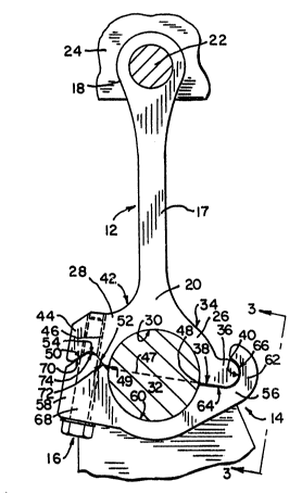
Fig. 1 shows a two cylinder internal combustion engine
8 having a connecting rods 10 embodying the present
invention. Each connecting rod 10 preferably includes only
three part~: a shank 12, an arcuate cap 14 and a bolt 16.
Shank 12 comprises an elongated central portion 17
which supports at one end an enlarged head 18 and at the
other end an enlarged cap-mounting portion 20. The head 18
is con~entionally formed to suitably receive a pin 22 of an
engine piston 24. The cap-mounting portion 20 is bifurcated
-6-
9626
,into two legs, lugged leq 26 and indented ~female~ leg 28.
The facing, inner surfaces of legs 26 and 28 form a semi-
circular surface 30 which forms one-half of the aperture for
receiving the crankpin 32 of the engine crankshaft.
Lugged leg 26 of shank 12 extends outward and downward
tas viewed in Fig. 2) from central portion 16 in an arcuate
manner. The outer surface 34 bulges outward at the end of ~
leg 26 to form thumblike lu~ 36. Lug 36 includes a flat ~ -
lower surface 38, which forms the bottom of leg 26 and which
merges into a semi-circular outwardly protruding surface 40.
The outer surface 42 of leg 28 curls outward and -~
, downward to form a lower leg 44. Lower leg 44 has an
internal threaded bore 46 whose longitudinal axis is
perpendicular to line 47 which extends between the lower
ends 48 and 49 of the facing inner surfaces of legs 26 and ~ ;
28 respectively.
In the embodiment of Fig. 6, the lower surface of lower
leg 44 is indented by a ~female~ groove 51 having sloping
~ides 50 and 52 which join at valley 54. The sides 50 and
52 of the groove may be straight as shown in the figures, or
they may be cur~ilinear. As will be seen, the indented
lower surface of lower leg 44 serves as a female component
of a male/female mounting junction, and in one particular
aspect, as groove 51 of a tongue-in-groove connection.
The second component of connecting rod 10, cap 14, has
a generally arcuate shape which comprises hook arc-end 56
an~ male arc-end 58. The inner facing surfaces of arc-ends
56 and 58 form a semi-circular surface 60 which ~oin with ;~
semi-circular surface 30 of shank 12 to form the complete
aperture for the crankpin 32. ~;~
Hook arc-end 56 culminates in a hook 62 which (as
viewed in Fig. 2) curls upward and then inward. The inner
-7-
2~9~20
surface of hook 62 includes flat surface 64 which can be
aligned with flat surface 38 of lug 36 and a semi-circular
surface 66 which can be aligned with semi-circular surface
40 of lug 36.
Male arc-end 58 of cap 14 has an internal through bore
68 which is coaxially alignable with bore 46 when cap 14 is ;
fastened to shank 12. In the embodiment of Fig. 6, the
upper end of male arc-end 58 is tapered and includes
slanting sides 70 and 72 which are designed to align with
sides 50 and 52 which form the groove in the end of lower
leg 44 of cap 14. The peak or tongue 73 of the tapered end
is truncated by flat surface 74.
Fig. 7 shows another embodiment of the ~unction of
lower leg 44 of the shank 12 with male arc-end 58 of cap 14.
In this embodiment, lower leg 44 and male arc-end 58 have
abutting surfaces 76 and 78 respectively which adjoin sides
52 and 72 respectively and which are at least partially
transverse to the direction of sides 52 and 72.
Alternatively, surfaces 76 and 78 could adjoin surfaces 50
and 70 respectively.
The third and final component of connecting rod 10 is
threaded bolt 16. It is made of steel and is chosen to be
able to slidably move through bore 68 of arc-end 58 and to
be threadably inserted into bore 46 of lower leg 44 of shank
12.
To assemble the connecting rod, semi-circular surface
66 of hook 62 is ~uxtaposed to surface 40 of lug 36, and
sides 50 and 52 of the groove of lower leg 44 are juxtaposed
with sides 70 and 72 respectively of male arc-end 58. Bolt
16 is inserted from the bottom of male arc-end 58 through
bore 68 and is screwed into bore 46 of lower leg 44.
. .
_~_
9 6 2 6
In one aspect of the invention, the tongue 73 of male
arc-end 58 is slightly inset toward the crankpin aperture
relative to the groove 51 of lower leg portion 44. For
example, in one embodiment, the distance from the outermost
point on luq 36 to the middle of tongue 73 is 51.3
millimeters while the co~responding distance to the middle
of groove 51 is 51.5 millimeters.
As a result, when cap 14 is loosely juxtaposed against
the legs of shank 12, bores 68 and 46 do not perfectly align ~-
and the crankpin opening is slightly out of round.
Tightening screw 16 causes male arc-end 58 to move toward
lower leg portion 44 approximately along an axis
perpendicular to line 47 and also causes cap 14 to move to ~-
the left (in the perspective of Fig. 2) approximately along
the axis of line 47. This firmly locks hook 62 against lug
36, rounds out the crankpin opening and locks surface 72
against surface 52. The resulting tension diminishes the
risk that bolt/fastener 16 will loosen and therefore `;
continually maintains a round crankpin opening.
To make the connecting rod shank by an extrusion; `
process as repr~sented in Fig. 8, a die 80 is preferably
constructed which has the desired elevational (as in the
perspective of Fig. 2) shape. This die 80 is moun~ed at the
end of a heating chamber 82 into which a charge of material,
such as aluminum, is placed. The chamber is then closed
except for the outlet provided by the die. The aluminum i9
then heated to a semi-molten state. The semi-molten
aluminum is then forced throuqh the die hole by an extrusion
ram. As a result, there is extruded from the die an
aluminum piece 84 which has the Fig. 2 elevational shape of ;~-
the crankshaft shank. A saw 86 is used to cut separate -
crankshaft shanks 87 each having the desired width.
_9_
~ 2~9626 ~;-
The one-~olt design, and the lack of any addLtional
parts, offse~s the normal wei~ht disadvantages of the
extrusion process. Also, the shapes of the connecting
portions of the apparatus aspect of the present invention
are sufficiently rounded to be made effectively and
efficiently by such an extrusion process. Thirdly, the
nature of the present invention is such that relatively
loose tolerances can be used. The cap can be made in a
similar manner.
The connecting rod shank and cap of the present
invention may also advantageously be made using a ~Ifine
blanking~ process, which is represented schematically in
, Fig. 9. A die plate 88 is formed to have an opening of the
size and shape of the periphery of the part. A punch 90
also of that size and shape is aligned with the opening. In
the opening of the die plate 88, there is a moveable anvil
92, which is urged toward the punch by a counterpunch
pressure. A sheet 94 of material is introduced between the
punch 90 and the die plate 88 and is immobilized relative to
the die plate 88. The punch 90 is forced through the sheet
of material and, overcoming the counterpunch pressure,
pushes a portion 96 of the material into the opening. The
portion 96 has the shape of the connecting rod part.
Although the especially preferred embodiments of the
invention have been described above, the invention claimed
is not so restricted. There may be other modi~ications and
changes to the~e embodLments which are within the scope of
the invention. For example, the bolt can be extended
through the shank leg and fastened in place with a nut.
Further, the hook-on-lug and the male/female junctions may
be shaped in many different ways which are within the scope
of the invention. For example, the male and female parts
--10--
21~9626
could be more cylindrical. ~lso, the female part could be
on the cap, with the male part on the leg. Moreover, the
extrusion and fine blanking processes may be used with
materials in addition to al~inum.