Language selection

Search

Patent 2119708 Summary

Third-party information liability

Some of the information on this Web page has been provided by external sources. The Government of Canada is not responsible for the accuracy, reliability or currency of the information supplied by external sources. Users wishing to rely upon this information should consult directly with the source of the information. Content provided by external sources is not subject to official languages, privacy and accessibility requirements.

Claims and Abstract availability

Any discrepancies in the text and image of the Claims and Abstract are due to differing posting times. Text of the Claims and Abstract are posted:

  • At the time the application is open to public inspection;
  • At the time of issue of the patent (grant).
(12) Patent: (11) CA 2119708
(54) English Title: NOTCHED HELICAL VANES IN THE FEEDING SECTION OF AN AXIAL AGRICULTURAL COMBINE
(54) French Title: DIFFUSEURS HELICOIDAUX COMPORTANT UNE ENCOCHE, POUR LA SECTION D'ALIMENTATION D'UNE MOISSONNEUSE-BATTEUSE A BATTEUR AXIAL
Status: Deemed expired
Bibliographic Data
(51) International Patent Classification (IPC):
  • A01D 41/12 (2006.01)
  • A01F 7/06 (2006.01)
(72) Inventors :
  • SOOTS, DANIEL L. (United States of America)
  • BRAUNHARDT, KLAUS ADAM (United States of America)
(73) Owners :
  • DEERE & COMPANY (United States of America)
(71) Applicants :
  • DEERE & COMPANY (United States of America)
(74) Agent: BORDEN LADNER GERVAIS LLP
(74) Associate agent:
(45) Issued: 1999-02-09
(22) Filed Date: 1994-03-23
(41) Open to Public Inspection: 1994-10-27
Examination requested: 1994-03-23
Availability of licence: N/A
(25) Language of filing: English

Patent Cooperation Treaty (PCT): No

(30) Application Priority Data:
Application No. Country/Territory Date
08/053,033 United States of America 1993-04-26

Abstracts

English Abstract


The feeding section of an axial flow agricultural combine
is provided with helical vanes. Each helical vane having an
upstream end that is provided with a notch in which crop
material is temporarily trapped. The notch is formed by
tapering the upstream end of the helical vane which is welded
to a transverse leading blade. The transverse leading blade
is provided with a tapered leading edge to prevent crop
material from hairpinning on the blade.


French Abstract

Dispositif d'alimentation d'une moissonneuse-batteuse à batteur axial doté de diffuseurs hélicoïdaux. Chaque diffuseur est doté d'une extrémité en amont présentant une encoche qui emprisonne temporairement les cultures. L'encoche est constituée de l'extrémité en amont effilée d'un diffuseur hélicoïdal qui est soudé à une lame transversale avançante. Celle-ci présente un bord avançant effilé qui empêche les cultures de bloquer les lames.

Claims

Note: Claims are shown in the official language in which they were submitted.

The embodiments of the invention in which an exclusive
property or privilege is claimed are defined as follows:
1. An axial flow agricultural combine comprising:
a supporting structure;
ground engaging means extending from the supporting
structure for transporting the supporting structure across a
field;
an axial rotor housing having a forward open inlet for
receiving harvested crop material, grates through which
threshed and separated grain is removed from the housing, and
a rear open outlet through which non-grain crop material is
removed from the housing;
an axial rotor for threshing and separating a harvested
crop, the axial rotor being housed in the axial rotor housing,
the axial rotor having a feeding section, the feeding section
of the rotor is provided with at least one helical vane, each
vane having an upstream end, the upstream end of the helical
vane is tapered and is provided with a transverse leading
blade, the transverse leading blade and the tapered helical
vane forming a notch, the transverse leading blade is provided
with a tapered leading edge having a point and a base edge,
the tapered helical vane merges with the transverse leading
blade between the point and the base edge of the transverse
leading blade.
2. An axial flow agricultural combine as defined by
claim 1 wherein the tapered helical vane has an upper edge
that is below the leading edge of the transverse leading blade
where the tapered helical blade merges with the transverse
leading blade.
3. An axial flow agricultural combine comprising:
a supporting structure;
ground engaging means extending from the supporting
structure for transporting the supporting structure across a
field;
an axial rotor housing having a forward open inlet for
receiving harvested crop material, grates through which
threshed and separated grain is removed from the housing, and
a rear open outlet through which non-grain crop material is
removed from the housing;

an axial rotor for threshing and separating a harvested
crop, the axial rotor being housed in the rotor housing, the
axial rotor having a feeding section, the feeding section is
provided with at least one helical vane, each helical vane
having an upstream end and a downstream end, the upstream end
of the helical vane having a transverse leading blade, the
transverse leading blade is provided with a tapered leading
edge having a point and a base edge, the helical vane merges
with the transverse leading blade between the point and the
base edge of the transverse leading blade.

Description

Note: Descriptions are shown in the official language in which they were submitted.


7 ~ 8
,

NOTCHED HELICAL VANES IN THE FEEDING SECTION
OF AN AXIAL AGRICULTURAL COMBINE

BACKGROUND OF THE INVENTION
1. Field of the Invention:
The present invention is directed to the helical vanes in
the feeding section of an axial flow agricultural combine.
2. Description of the Prior Art:
Agricultural combines are large machines that harvest,
thresh, separate and clean an agricultural crop. The
resulting clean grain is stored in a grain tank located on the
combine. The clean grain can then be transported from the -~
grain tank to a truck, grain cart or other receiving bin by an
unloading auger.
Axial flow combines have one or two large rotors arranged
along the longitudinal axis of the machine. The rotors have
feeding, threshing and separating sections axially arranged
along the rotor. Harvested crop material is introduced by the
feederhouse to the feeding section of the axial rotor. The
fee~ing section of the rotor maybe provided with a propeller
assembly similar to that disclosed in U.S. Patent 4,148,323; -
or a helical blade assembly as disclosed in U.S. Patents -
4,266,560, 4,362,168 and 4,367,757.
One problem encountered by axial flow combines i6 that
straw may slip forward off the helical vanes of the feeding
section of the rotor into the gap formed between the rotor
drum and the rotor bearing support. ~ ;
SUMMARY
It is an object of the present invention to provide an
improved helical vanes for the feeding section of an axial -~
flow rotor which prevent straw from slipping into the gap
formed by the rotor drum and the rotor bearing support.
It is a feature of the present invention that the ~ ;
improved helical vanes are notched at their upstream end.
It is another feature of the present invention that the
helical vanes are provided with transverse leading blades.


: ~ . : .... .-,

~. . .. . .. ,.:~ , ,.,. :.. . :,, , -- ,. ... i ., .

7 3 8

It is another feature of the present invention that the
transverse leading blades are provided with tapered leading
edges that are tapered towards the direction of rotation.
A beater directs the harvested crop material from the
feederhouse to the inlet of the axial crop processing unit.
The inlet of the axial crop processing unit is provided with
an inlet transition section comprising part of the rotor
; housing and the feeding section of the rotor. The feeding
section is provided with outwardly extending helical vanes.
Each vane is provided with an upstream end and a downstream
end. The upstream end of the vane is tapered and merges with
a transverse leading blade to form a notch.
' Straw engaging one of the helical vanes of the feeding
- section, may still slip forward, but is temporarily trapped in
the notch. Straw will nest in the notch until centrifugal
forces throw the straw outwardly so it engages the vanes in
the feeding section housing. To prevent straw from
hairpinning around the transverse leading blade, the blade is
provided with a tapered leading edge.
- 20 BRIEF DESCRIPTION OF THE DRAWINGS
Figure 1 is a semi-schematic side view of an axial flow
~' agricultural combine.
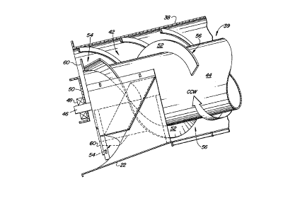
Figure 2 is a side view of the feed section of the axial
flow rotor.
Figure 3 is a front view of the feed section of the axial
- flow rotor. ~-
DETAILED DESCRIPTION
Figure 1 shows an agricultural combine 10 comprising a
~' supporting structure 12 having ground engaging means 14
sl 30 extending from the supporting structure. The ground engaging
~' means comprises wheels that are used for transporting the
supporting structure across a field. A harvesting platform 16
is used for harvesting a crop and directing it to a
' feederhouse 18. The harvested crop is directed by the
;~ 35 feederhouse 18 to a beater 20. The beater directs the crop
' upwardly through an inlet transition section 22 to the axial
' crop processing unit 24.


:'

7 ~ 8

The crop processing unit 24 threshes and separates the
harvested crop material. Grain and chaff fall through grates
on the bottom of the unit 24 to cleaning system 26. The
cleaning system 26 removes the chaff and directs the clean
grain to a clean grain elevator (not shown). The clean grain
elevator deposits the clean grain in grain tank 28. The clean
grain in the tank can be unloaded into a grain cart or truck
by unloading auger 30.
Threshed and separated straw in discharged from the axial
crop processing unit through outlet 32 to discharge beater 34.
The discharge beater in turn propels the straw out the rear of
the combine. The operation of the combine is controlled from
operator's cab 36.
The axial crop processing unit comprises a cylindrical
rotor housing 38 and a rotor 3g located inside the housing 38.
The rotor housing is provided with an inlet transition section
22 in which the feeding section 42 of the rotor is located.
As viewed from the front the rotor rotates counterclockwise as
indicated by arrow CCW. The rotor comprises a rotor drum 44 ~ ;
having a stub shaft 46 that is mounted in support bearing 48.
The bearing 48 is mounted to cross member 50 that is mounted -
to the sideheets of the combine which forms the combine's
supporting structure. -~
The feeding section of the rotor drum 44 is a cylindrical -~
r 25 member having outwardly extending helical vanes 52. Each vane
has an upstream end 54 and a downstream end 56 reflecting the -
movement of harvested crop material through the axial crop
processing unit 24. The upstream portions of the helical
' van~s are tapered and terminate in a transverse leading blade
60. The transverse leading blade 60 is provided with a
tapered leading edge 61 that is tapered towards the direction
of rotation to prevent hairpinning of straw and other crop
material on this blade.
The tapered helical vane 52 is welded to the transverse
leading blade 60 between the point 62 and the base edge 64 of
the transverse leading blade at 66. The upper edge 67 of the
' tapered helical vane is below the tapered leading edge of the


7 ~
.
cransverse leading blade at merge point 66. As such, the
tapered helical vane and the transverse leading blade form a
notch or dead zone in which harvested crop material is
. temporarily trapped as it slips forward off the helical vanes.~~ 5 The material is trapped there until it is centrifugally
expelled outwardly by the rotor against the rotor housing.
The present invention should not be limited by the above-
described embodiment, but should be limited solely by the
claims that follow.
',


, ': '


~ ~.
','


Representative Drawing
A single figure which represents the drawing illustrating the invention.
Administrative Status

For a clearer understanding of the status of the application/patent presented on this page, the site Disclaimer , as well as the definitions for Patent , Administrative Status , Maintenance Fee  and Payment History  should be consulted.

Administrative Status

Title Date
Forecasted Issue Date 1999-02-09
(22) Filed 1994-03-23
Examination Requested 1994-03-23
(41) Open to Public Inspection 1994-10-27
(45) Issued 1999-02-09
Deemed Expired 2005-03-23

Abandonment History

There is no abandonment history.

Payment History

Fee Type Anniversary Year Due Date Amount Paid Paid Date
Application Fee $0.00 1994-03-23
Registration of a document - section 124 $0.00 1994-09-09
Maintenance Fee - Application - New Act 2 1996-03-25 $100.00 1996-03-22
Maintenance Fee - Application - New Act 3 1997-03-24 $100.00 1997-03-21
Maintenance Fee - Application - New Act 4 1998-03-23 $100.00 1998-03-20
Final Fee $300.00 1998-10-08
Maintenance Fee - Patent - New Act 5 1999-03-23 $150.00 1999-03-22
Maintenance Fee - Patent - New Act 6 2000-03-23 $150.00 2000-03-22
Maintenance Fee - Patent - New Act 7 2001-03-23 $150.00 2001-03-22
Maintenance Fee - Patent - New Act 8 2002-03-25 $150.00 2002-03-22
Maintenance Fee - Patent - New Act 9 2003-03-24 $150.00 2003-03-21
Owners on Record

Note: Records showing the ownership history in alphabetical order.

Current Owners on Record
DEERE & COMPANY
Past Owners on Record
BRAUNHARDT, KLAUS ADAM
SOOTS, DANIEL L.
Past Owners that do not appear in the "Owners on Record" listing will appear in other documentation within the application.
Documents

To view selected files, please enter reCAPTCHA code :


To view images, click a link in the Document Description column. To download the documents, select one or more checkboxes in the first column and then click the "Download Selected in PDF format (Zip Archive)" or the "Download Selected as Single PDF" button.

List of published and non-published patent-specific documents on the CPD .

If you have any difficulty accessing content, you can call the Client Service Centre at 1-866-997-1936 or send them an e-mail at CIPO Client Service Centre.


Document
Description 
Date
(yyyy-mm-dd) 
Number of pages   Size of Image (KB) 
Cover Page 1999-02-03 1 48
Claims 1995-04-14 2 126
Drawings 1995-04-14 3 190
Description 1995-04-14 4 241
Claims 1997-12-23 2 74
Representative Drawing 1999-02-03 1 14
Cover Page 1995-04-14 1 52
Abstract 1995-04-14 1 35
Correspondence 1998-10-08 1 30
Prosecution Correspondence 1994-03-23 5 214
Examiner Requisition 1996-11-29 2 62
Prosecution Correspondence 1997-04-07 2 52
Fees 1997-03-21 1 66
Fees 1996-03-22 1 48