Note: Descriptions are shown in the official language in which they were submitted.
~~.~.~~~'~
gIELn og Tsa iio~r
The invention deals with an installation for cold
rolling of strip-shaped rolling material.
$~clCGR00ND.OF TSE INVEI~~TION
The use of single stand reversing mills for cold
rolling strip-shaped rolling material is well known. In such
single stand reversing mills, up to approximately 450,000 tons
per year of hot rolled strip can be cold rolled. If the steel
plant has a higher output of hot rolled strips, then any hot
rolled strips exceeding the approximately 450,000 tons per year
yield could not be cold~rollec~ and a second single stand
reversing mill or train must be erected.
Another possibility is to provide a multi-stand, for
instance, a four or five-stand tandem train, which works
economically starting with an output of 1 million tons per
year. In so-called "mini-steel plants," which have an output
of approximately 700,000 tons per year, the use of a fowc-stand
tandem train for cold rolling strips is not worthwhile for
economic reasons. The single-stand reversing mill or train for
cold rolling strips however is inadequate for rolling the
entire output of a "mini-steel mill" into cold rolled strips.
2
The solution of providing two single-stand reversing trains in
one single "mini-steel plant" is also cost intensive because
the two trains are not operating at full load capacity and
since relatively high installation invention must be undertaken
for the two trains.
Another disadvantage of a single reversing stand,
compared to multi-stand installations, is the inability to use
a rag or roll in the last pass.
It is therefore an object of the invention to provide
a cold rolling mill for a widely distributed assortment of
strip-shaped rolling material.
Another object of the invention is to provide a
reversing compact installation for cold rolling strip-shaped
rolling material which has a yearly capacity of approximately
700,000 tons of cold rolled strip and which is thus optimally
suited for use in "mini steel plants" -- i.e. in production
range between a reversing stand and a tandem train.
Yet another object of the invention is to assure that
work rolls with variable diameters can be used to assure
optimum pass reductions.
ran-~s~ss
3
i
CA 02119957 2002-03-05
A further object of the invention is to permit use
of rag or roughened work rolls for the last pass.
Additionally, an object of the invention is to
simplify and speed up the change of work rolls in case of
friction driven work rolls, which again favors a higher
throughout.
SUI~1ARY OF THE INVENTION
These and other objects of the invention, which
shall be hereafter apparent, are achieved by a reversing
compact installation for cold rolling strip-shaped rolling
material, with a reversing stand disposed between two
reversible reels and a reel from which the strip to be used
can be taken off .
More specifically, the present invention provides an
installation for cold rolling a strip-shaped rolling material,
the installation comprising two reversing reels, a first
reversing stand disposed between the two reversing reels, a
reel from which the strip to be used can be taken off, and a
second reversing stand provided in the rolling line of the
first reversing stand wherein both first and second reversing
stands are adjustable in accordance with consecutive passes
4
CA 02119957 2002-10-22
for performing the rolling process, wherein both first and
second stands are simultaneously operated. The reversing
stands each have drive means for directly driving work rolls,
and the reversing stands each further comprise linearly
displaceable means arranged on a side of a respective
reversing stand opposite to a side on which the drive means is
arranged for a quick change of the work rolls with which the
work rolls provided with work rolls blocks in the cassette
type of construction can be changed, whereby replacement of
work rolls of different diameters and/or different roughness
is possible.
The present invention also provides a method of
coldrolling of a strip-shaped rolling material, the method
comprising the steps of (a) providing a cold rolling
installation including two reversing reels, a first reversing
stand disposed between the two reversing reels, a reel from
which a strip to be used can be taken off, and a second
reversing stand provided in the rolling line of the first
reversing stand, the first and second stands being adjustable in
accordance with performed consecutive passes, operating
simultaneously, and each having drive means for directly driving
respective work rolls, (b) unwinding the strip-shaped rolling
material from one of the two reversing reels, rolling the
unwound strip-shaped rolling material in the first stand and
then second stand, and winding rolled strip-shaped material
4a
CA 02119957 2002-10-22
onto another of the two reversing reels, (c) reversing the
direction of rotation of the respective work rolls in the
first and second stands, (d) unwinding the strip-shaped
rolling material from another of the two reversing reels,
. rolling the strip-shaped rolling material in the second stand
and then in the first stand, and winding the rolled strip-
shaped rolling material onto the one of the reversing reels,
(e) repeating steps (c) and (d) at least one more time, and
changing, if necessary, in a last repeat of steps (c) and (d),
the work rolls of one of the first and second stands, which is
located downstream of the other of the first and second stands
in a rolling direction, by work rolls having different
roughness.
Usually hot rolled strips were cold rolled in
several passes. Tn a multi-stand tandem train, these passes
are rolled in the course of one single passage, while in a
single stand reversing train, three to seven passages must be
performed.
Only'two to three passages are however necessary in
the two stand reversing train of the invention, so that a large
throughput is achieved in the same time period compared to the
single stand reversing trains. The installation proposed here
4b
~~.~.~~~'r
is considerably more cost effective than two single-stand
reversing trains. Also, the area requirement for the proposed
two stand reversing train is smaller than in the case of two
single stand reversing trains disposed, for instance, parallel
to one another. It must be added that the two-stand reversing
train can be arranged to lie in line with the strip treatment
stations disposed upstream of the rolling train, whereas the
two single stand reversing trains required for an output of
approximately 700,000 tons must always be fed coils of hot
rolled strips, through switches and displacement devices. It
is also essential that, compared to the single-stand reversing
train, a considerably higher strip tension level be achieved so
that the reducing characteristic of a four to six-stand, tandem
train can be achieved.
The invention will be better understood, by the
Detailed Description of the Preferred Embodiment, in connection
with the drawings of which
Figure 1 is a schematic of a two-stand reversing
train of the invention;
~m
~' .~. .~~ ~ .~ v ~\r
Figure 2 is a cross-sectional through the two-stand
reversing train in the invention; and
Figures 3a and 3b depict a two°stand reversing train
connected to a push type pickling installation.
DBTgIIZED DERCRIPTIOId OF THE PREFERRED EMBODIMENT
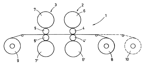
Referring now to the drawings, wherein lake numerals
reflect like elements, throughout the several views, Figure 1
shows a cold rolling train 1 comprising two reversing stands 2,
3 - in this case with four-high stands having Work rolls 4, 4~;
5, 5~ and backup rolls 6, 6~; 7, 7°. The two reversing stands
2, 3 are disposed between two reels 8, 9, which can provide the
necessary tension for the reeling or unreeling in reversing
operation.
A reel 10 serves for the taking-off hot rolled strip
for the first pass and possibly for coiling the hot rolled
strip of an upstream located processing line. The reel 10 can
operate with a lower tensile force, compared to the reels 8, 9.
The strip, which has to be taken-off the reel 10 during the
reversing process in the course of which reels 8 and 9 are
used, can be prepared to such an extent that following one
rnnasess
6
~1.~.~~ ~'~
rolling process, the next strip can be rolled without any large
delay.
Figure 2 depicts friction driven rolls in the work
rolls 4, 4' (5, 5'). Drives 11, 11' operate through a gear box
12 and spindles 13, 13' upon the backup rolls 6, 6' (7, 7'). A
roll changing device 14 pushes, in the course of work roll
changes, the new prepared set of work rolls from the changing
table 15 into the stand 3. The work rolls present in the stand
2 are pushed herein upon the depositing or storage table 16.
This enables a rapid change of work rolls. For instance, three
to five passes can be performed with one set of work rolls and
the respectively last pass (for instance pass 4 or pass 6) can
be performed after the work rolls have been replaced by a set
of work rolls having a different rag or roughness.
Figures 3a and 3b show the two-stand reversing train
downstream of a push type pickling installation 17. The reel
can be seen in Figures 3a, which reels up the strip emerging
from the pickling installation 17, while the previous strip is
rolled in the cold rolling train 1 in a reversing manner.
Following thereupon, the reel 10 serves for unreeling the strip
into the cold rolling train.
Figure 3b shows that the reel 10 is a reversing reel
10' which permits a simultaneous reeling and unreeling of the
~n~ssss
7
6 f
K.$
strip emerging from the push type pickling installation and
also permits directing of the same towards the cold rolling
train 1.
While the preferred embodiment of the invention lass
been depicted in detail, modifications and adaptations may be
made thereto, without departing from the spirit and scope of
the invention, as delineated in the following claims:
x~i~x~
8