Note: Descriptions are shown in the official language in which they were submitted.
21200~2
TITLE OF INVENTION: LEAFCUTTER BEE MANAGEMENT SYSTEM
INCLUDING A LAMINATE BEE BOARD
D E S C R I P T I O N
BACKGROUND OF THE INVENTION
Technical Field. This invention relates generally to
management systems and nests for leafcutter bees, and
specifically to a laminate bee board with a flexible
permanent backing to facilitate handling and management.
Backqround: Management of leafcutter bees for
pollenization of alfalfa crops has had a significant
effect on the commercial success of the alfalfa seed
industry. The leafcutter bee is managed to time its life
cycle to coincide with the alfalfa crop management cycle.
The leafcutter bees are used to pollinate the alfalfa
blossoms. A blossom appears on the alfalfa plants
approximately 45 days after the alfalfa hay has been "set
back", usually by mowing, swathing or roto-beating.
The life cycle of the bee is managed through
temperature control of its environment. After the mature
bees emerge, the females begin to nest within 2-3 days.
The females always nest in existing tunnels. The female
bee chews a piece of a leaf out of plants in the immediate
area of the nest. The bee then puts the piece of leaf in
the tunnel to form a cup. Next, she fills the cup with a
nectar and pollen mixture, lays an egg and then caps the
cup with another piece of leaf, forming a cell. She
repeats these steps until the tunnel is filled with cells.
The incubation of the egg is also managed. The egg
2120042
hatches into a larva, which eats the nectar and spins a
cocoon. The cocoon normally remains dormant for the
winter. A mature bee will emerge from the cocoon in
response to a specific warm temperature range. This
emergence is again timed to coincide with the blossoming
of the alfalfa. This management cycle is repeated.
With the growth of the industry of raising
pollinators, certain management problems have become
significant. Leafcutter bees are susceptible to predators
and certain diseases, the most significant of which is
called chalkbrood. Chalkbrood can cause up to a 50~
mortality to the bee larvae. This disease has increased
in prevalence in recent years. Various predator insects
and parasites also have a significant effect on the
production of leafcutter bees.
In response to these management problems the industry
has instituted a number of management practices. The use
of laminated nesting materials, specifically wood
laminates, provide superior predator and parasite
prevention along with a natural attraction for the bees.
However, laminate bee boards tend to be expensive and
require more handling in assembling and disassembling them
for cell removal, cleaning and sterilization.
Consequently, synthetic bee board materials, such as solid
polystyrene blocks, have experienced a rise in popularity.
These solid bee boards lend themselves to automated cell
removal, cleaning and sterilization. They are, however,
prone to predator infestation and tampering by other
animals. Additionally, the bees are not naturally
attracted to the synthetic material for nesting.
Current sterilization techniques involve removing the
cells from the bee nest, dipping the cells in a
sterilizing solution such as a chlorine solution and air
2120042
drying the cells. Cleaning and sterilization of the nests
is done separately.
Problems with the current management techniques
include the necessity of carrying out the sterilization in
multiple steps, using multiple machines and a relatively
intensive labor input, especially with laminate type bee
boards. Additionally, if not performed carefully
contamination can be spread instead of inhibited. The
laminates can be difficult to handle and assemble and
disassemble for the sterilization procedures. A more
thorough discussion representative of current management
options and practices and their associated advantages and
disadvantages is contained in Bulletin No. 538, from
Cooperative Extension System, University of Idaho, College
of Agriculture, "Alfalfa Leafcutting Bee Management In
Idaho" ~ por~teA hy referenee hc~ci~.
What is needed is simpler effective tool for
management of leafcutter bees to help prevent disease and
inhibit predators.
It is an object of the present invention to provide a
laminate nest which takes advantage of the inherent
predator resistance of laminate nests, yet which is simple
to manage, clean and sterilize.
It is a further object of the present invention to
provide a laminate nest that requires less steps and less
management when processed during nest management.
DISCLOSURE OF INVENTION
The present invention provides a bee nest made from a
plurality of bee board laminates held in close side by
side relation by a permanent, flexible and lightproof
backing material. The nest includes a means for
releasably opening and closing the nest at the front edges
21200q2
of the laminates. Each laminate has a front edge, back
edge and two side edges bounding two generally planar
surfaces. The planar surfaces have closely parallel
spaced elongated grooves formed therein extending between
the front and back edges. The grooves are aligned to form
tunnels in the nest when the laminates are oriented in
close, parallel juxtaposition to each other.
The flexible, lightproof binding is permanently
attached to the back edge of the laminates. The
attachment of the binding allows the laminates to be
adjustably oriented between a closed position, having the
laminates in a side by side orientation, and an open
position with the planar surface of two adjacent laminates
positioned to form one continuous planar surface of
grooves, for cleaning and sterilization management. The
closed position has the grooves of the laminates forming
the tunnels of the nest. The binding maintains the
correct orientation of the laminates, while simultaneously
allowing the laminates to be manipulated and positioned
for management and returned to the desired orientation
with a minimum of labor and handling.
BRIEF DESCRIPTION OF THE DRAWINGS
Fig. 1 is a front perspective view of the present
invention.
Fig. 2 is an detailed front perspective view of the
present invention.
Fig. 3 is a second detailed front perspective view of
the present invention.
Fig. 4 is a end view showing the invention in an open
position with the planar surface of two adjacent laminates
21200~2
positioned to form one continuous planar surface of
grooves.
Fig. 5 is a top isometric view of the present
invention.
BEST MODE FOR CARRYING OUT INVENTION
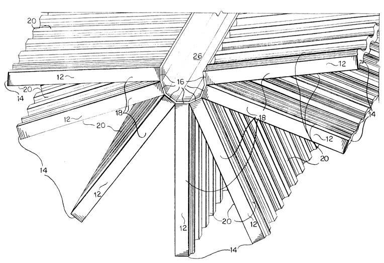
Referring now to Figures 1-5, nest 10 generally is
made up of a plurality of laminates 12 positioned in close
side by side relation and permanently bound at their back
edges 16 to flexible backing 26 and held in this closed
position by fastener 28 and cleat 30.
Each laminate 12 is generally rectangular in shape
with a perimeter defined by front edge 14, back edge 16
and side edges 18. Each laminate 12 has two planar
surfaces 20, which in turn each have closely parallel
spaced grooves 22 formed therein. Grooves 22 are shaped
and positioned to form tunnels 24 when a plurality of
laminates 12 are placed in close juxtaposition, as seen in
Figures 2 and 3. Preferably, laminates 12 are formed out
of wood, but they could also be formed out of polystyrene,
for example, or any other suitable material.
Binding 26 permanently attaches to back edge 16 of
each laminate 20 and also covers outer planar surface 20
on the endmost laminates 20 on each end of nest 10 to
define the overall length of nest 10. Binding 26 is made
from a flexible and lightproof material. In the preferred
embodiment, binding 26 is a dark colored vinyl, such as
PVC fabric, but binding 26 can be formed from any
appropriate material that is durable, light proof and
flexible.
Fastener 28 is attached to binding 26 on one outside
surface of endmost laminate 20. Cleat 30 is attached to
binding 26 on the outside surface of the opposite endmost
21200~2:
-- 6 --
laminate 20. In the preferred embodiment fastener 28 is a
cord, but fastener 28 can be any reclosable device
including a strap and buckle, velcro, small gauge chain
and hook or strap with a snap closure. In the preferred
embodiment cleat 30 is formed by a pair of raised small
metal discs or washers for anchoring fastener 28. Cleat
30 may also be any appropriate device or structure or
device that works in cooperation with fastener 28 to allow
nest 10 to be releasably closed.
In practice, a plurality of boards of laminate 12 are
permanently attached by back edge 16 to binding 26 to
obtain nest 10 of desired dimensions depending on the
individual management system in place. Each laminate 12
is oriented so that grooves 22 form tunnels 24 when two
laminates 12 are juxtapositioned. Additionally, binding
26 is flexible enough to allow any two sequential boards
of laminate 12 to be opened with back edge 16 of both
boards of laminate 10 in juxtaposition, as best seen in
Figure 4, such that planar surface 20 of both boards form
one continuous surface, to allow improved cleaning and
sterilization of tunnels 24 and surfaces 20.
Cleaning and sterilization management can be automated
and reduced to a single step system. In the single-step
system two sequential boards of laminate 12 are opened
such that planar surface 20 of both boards form one
continuous surface and the "pencils" of cells or cocoons
are pushed out. The pencils are pushed into a tumbler
which functions to break up the pencils into loose cells
and simultaneously wash and sterilized the cells. The
sterilized loose cells are moved to drying trays and are
ready for dormant storage after drying. The continuous
surface formed by planar surface 20 of two sequential
boards of laminate 12 is scrubbed and sterilized in the
2120042
same step as pencil removal. Nest 10 is manipulated
through the automated process in a stepped manner that
allows the one-step system to be performed on one pair of
sequential planar surfaces 20 and repeated on the next
sequential pair of planar surfaces 20, until all planar
surfaces 20 of nest 10 have been processed.
Binding 26 keeps laminates 12 in alignment in both the
open position for cleaning as seen in Figs. 3 and 5 and
the closed position, as seen in Figs. 1 and 2, when
tunnels 24 of nest 10 are occupied. This greatly reduces
the labor and decreased the handling required in the
management of nest 10.
While there is shown and described the present pre-
ferred embodiment of the invention, it is to be distinctly
understood that this invention is not limited thereto but
may be variously embodied to practice within the scope of
the following claims.