Note: Descriptions are shown in the official language in which they were submitted.
2120092
2320-33-00
PATENT
TRIANGULAR DEPOSITION CHAMBER FOR A
VAPOR DEPOSITION SYSTEM
BACKGROUND OF THE INVENTION
Field of the Invention
This invention relates to an improved method of and apparatus
for the manufacture of stiff, strong, lightweight structures, and
more particularly, to an improved method of and apparatus for the
manufacturing of silicon carbide and/or silicon lightweight
structures by the utilization of improved vapor deposition
techniques. Further, this invention relates to a triangular
chemical vapor deposition arrangement which can provide high yields
of thick ceramic materials or parts from a vapor deposition system.
Description of Related Art
In the manufacture of ceramic materials by chemical vapor
deposition, gases are introduced into a hot furnace where they
react at the walls of the furnace or at the surface of a substrate
or mandrel positioned in the furnace to form a solid deposit or
coating thereon. Typically, a vacuum furnace designed in the shape
of a tubular cylinder having a circular cross section is used for
chemical vapor deposition. In the formation of a coating of a
ceramic material such as silicon carbide (hereinafter referred to
as "SiC"), methyltrichlorosilane (CH3SiC13, for convenience termed
as "MTS" hereinafter), hydrogen (H2) and argon (Ar) gases are
introduced in the reaction chamber through stainless steel
injectors. Since MTS is a liquid at room temperature, Ar gas is
bubbled through the MTS and carries MTS vapor to the injectors.
Unreacted gases, products of reaction, and undeposited solids are
evacuated from the furnace and cleaned in a gas scrubber. Thick
2120092
2320-33-00
PATENT
deposits (greater than 10 mils) of SiC can be manufactured using
this process. Typical conditions for the manufacture of SiC by
chemical vapor deposition are:
Substrate Temperature 1350C (2462F)
Furnace or Reaction Chamber Pressure 200 torr
Partial Pressure of Gases Ar 125 torr
H2 60 torr
MTS lS torr
SiC parts are fabricated by the aforementioned process on a
mandrel which is placed perpendicular to the flow, i.e., an
impinging flow configuration. The reagents are illLlGduced from
several injectors which impinge on the mandrel at different
locations and thus produce a more uniform deposit over the whole
mandrel area. Efficient recovery of the deposited material without
cracking or stressing is an important issue. In order to prevent
deposited material from cracking, the mandrel may be isolated from
the rest of the furnace using a gas shroud technique as disclosed
in Keeley et al., U.S. Patent No. 4,990,374; or a flexible body is
used to prevent backside growth on the mandrel as disclosed in
Goela et al., U.S. Patent No. 4,963,393, both of which patents are
assigned to the assignee of the present invention. The impinging
flow configuration is preferred when specific parts are to be
manufactured by deposition of material on male molds; such as,
cones, discs, and cylinders of uniform thickness are required.
However, when the objective is to fabricate large amounts of bulk
sheet stock or deposit material in female molds, this configuration
2120092 2320-33-00
PATENT
is inferior due to low values for reagent utilization efficiency.
Reagent utilization efficiency, with respect to vapor
deposited material, in general, is defined as a ratio of the weight
of material deposited on the mandrel to the total weight of
material to be deposited that is contained in the reagents. With
respect to SiC, reagent utilization efficiency is defined as a
ratio of the weight of SiC deposited on the mandrel to the total
weight of SiC in the reagents. In an impinging flow configuration,
the reagent utilization efficiency is usually less than 20%. Since
the walls of the chemical vapor deposition reactor are also heated,
material may deposit on these walls and in the exhaust regions of
the furnace. In most cases this material is treated as waste. In
principle, one can minimize this waste by increasing the size of
the mandrel. However, this requires increasing the furnace
diameter, which is costly in a vacuum system. Preferably, the
mandrel or mandrels should be so arranged in a chemical vapor
deposition furnace to provide the maximum surface area available
for deposition while occupying a minimum amount of the furnace
floor surface area.
Further, undeposited solids must be removed by a filter system
prior to the gases entering the vacuum pumping system. Due to the
physical properties of SiC (hardness, 2540 kg/mm2 (Rnoop 500g
load); fracture toughness, 3.3Mn/ml~ (micro-indention); and density
3.21 g/cm3), particles of undeposited material which pass through
the exhaust system result in significant wear on process piping,
seals, filters and other particulate removal components.
Depositing SiC, which would normally be exhausted from the chemical
2120092
2320-33-00
PATENT
vapor deposition furnace, would present the added advantage of
reducing the wear on exhaust gas processing equipment. The
resulting reduction in equipment cost associated with the
manufacture of SiC would significantly reduce the overall cost of
manufacture.
A deposition chamber in which the flow is parallel to the
deposition surface provides good potential to obtain high
deposition efficiency. Four-sided deposition chambers, formed from
mandrel plates in the shape of a box which is open on both ends for
the passage of reagents, are known in the art. Normally, sheets of
material deposited on the inside surfaces of the mandrel plates
arranged in this manner tend to bow and may crack. This condition
would be exaggerated in the case of SiC due to its extreme hardness
and elastic modulus. Further, material deposited on the inside
surfaces of the four walls of the mandrel box grow together at the
corners during the deposition process. Normally, this does not
present a problem with soft material which is weaker than SiC, as
it can be scored, fractured at the score line and easily machinp~.
Due to the unique properties of SiC, extreme hardness and high
strength, the scoring, fracturing and mach;ning of SiC would be
extremely difficult. Further, this additional step reduces the
process yield.
SUMMARY OF THE INVENTION
An object of this invention is to provide a means for the
manufacture of material by chemical vapor deposition that affords
the maximum surface area for deposition while occupying minimum
- 4 -
2120092 2320-33-00
furnace floor surface area.
A further object of this invention is to provide a means for
the manufacture of material by chemical vapor deposition that
affords easy and efficient removal of chemical vapor deposited
material with minimal loss of product due to cracking.
Another object of this invention is to provide a means for the
manufacture of material by chemical vapor deposition that affords
a high reagent utilization efficiency.
Another object of this invention is to provide an apparatus
having deposition surfaces both parallel and perpendicular to the
direction of gas flow.
Another object of this invention is to provide an apparatus
which will reduce the wear on process equipment caused by abrasive
waste material.
Still another object of this invention is to provide a
structure for the deposit of material by chemical vapor deposition
that results in chemical vapor deposition material which requires
a minimum of post-deposition machining.
These and other objectives of the invention, which will become
apparent from the following description, have been achieved by a
novel apparatus for the manufacture of structures formed by vapor
deposition, comprising a vertical triangular vapor deposition cell
which is described hereinbelow. The triangular vapor deposition
2120092
2320-33-00
PATENT
cell of this invention overcomes many of the aforementioned
drawbacks and provides high yields of high quality and thick
ceramic material such as SiC.
The apparatus of this invention, for the manufacture of
materials by vapor deposition,comprises a means for supplying a gas
at a controlled rate to a novel vapor deposition cell contained
within a vapor deposition furnace. The furnace has a plurality of
side walls, a top cover and a bottom cover. A number of first
mandrel plates are arranged to form the vapor deposition cell
having an outside, an inside, a first end, and a second end. The
inside of the vapor deposition cell defines a vapor deposition
chamber having a triangular cross section. Preferably, the cross
section of the vapor deposition cell is an eguilateral triangle.
The first mandrel plates are made from a material suitable for use
in a vapor deposition furnace. A means to heat the vapor
deposition furnace is provided. The gas is conducted to the first
end of the vapor deposition chamber, flows through the chamber, and
exits the vapor deposition chamber carrying with it any undeposited
solids in the gas stream. The gas flowing through the vapor
deposition chamber flows parallel to the surface of the heated
mandrel plates. Material is deposited onto the heated mandrel
plates to form a vapor deposited structure.
In addition, a second mandrel plate may be located within the
vapor deposition chamber or immediately outside the vapor
deposition chamber in a spaced relationship to the second end of
the vapor deposition chamber and perpendicular to the flow of the
reaction gas. A number of vapor deposition cells, with or without
A
2120092
2320-33-00
PATENT
the second mandrel plates, can be arranged to form a vapor
deposition unit having increased surface area. For example, with
the aforementioned triangular form described herein, six vapor
deposition cells can be arranged in the shape of a hexagon.
The vapor deposition cell can be oriented horizontally or
vertically. When the vapor deposition cell is oriented vertically,
the gas can be made to flow substantially in the same direction to
the force of gravity or substantially in the opposite direction to
the force of gravity. The apparatus of this invention can be used
for vapor deposition and, in particular, chemical vapor deposition
of materials such as, but not limited to, SiC, zinc sulfide, and
zinc selenide. A vapor deposition cell of this invention arranged
in this manner can achieve a reagent utilization efficiency of at
lS least 50%, preferably at least 55%, and more preferably at least
75%.
Also, this invention includes a process for the manufacture of
materials by vapor deposition comprising supplying a gas at a
controlled rate to a novel vapor deposition cell contained in a
vapor deposition furnace as described hereinabove. The vapor
deposition chamber is heated and the gas is conducted to the first
end of said vapor deposition chamber. The gas flows through the
vapor deposition chamber from the first end to the second end where
any unreacted gases and undeposited solids exits the vapor
deposition chamber. The gas flow is parallel to the surface of the
heated mandrel plates. Material is deposited onto the heated
mandrel plates to form a vapor deposited structure. The process of
this invention can be used for vapor deposition and, in particular,
2120092
2320-33-00
PATENT
chemical vapor déposition of materials such as, but not limited to,
SiC, zinc sulfide, and zinc selenide. A vapor deposition process
of this invention can achieve a reagent utilization efficiency of
at least 50%, preferably at least 55%, and more preferably at least
75%.
BRIEF DESCRIPTION OF THE DRAWINGS
With this description of the invention, a detailed description
follows with reference being made to the accompanying figures of
drawings which form part of the specification related thereto, in
which like parts are designated by the same reference numbers, and
of which:
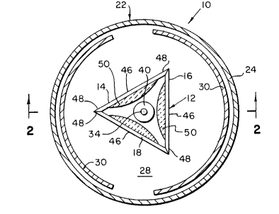
Fig. 1 is a top-plan view of a chemical vapor deposition furnace
illustrating the arrangement of a single chemical vapor deposition
cell of this invention in the furnace;
Fig. 2 is a cross-sectional view taken along line 2-2 of Fig. 1
illustrating the arrangement of a chemical vapor deposition furnace
using the chemical vapor deposition cell of this invention with gas
flow in the same direction as the force of gravity;
Fig. 3 is a top-plan view of a chemical vapor deposition furnace
illustrating the arrangement of multiple chemical vapor deposition
cells of this invention within a furnace;
Fig. 4 is a cross-sectional view taken along line 4-4 of Fig. 3
illustrating the arrangement of multiple chemical vapor deposition
2120092
2320-33-00
PATENT
cells of this invention within a furnace;
Fig. 5 is a cross-sectional view illustrating a mandrel plate at
the bottom of the furnace perpendicular to the flow of the reaction
gas;
Fig. 6 is a cross-sectional view illustrating the arrangement of a
chemica} vapor deposition furnace using the chemical vapor
deposition cell of this invention with gas flow opposite to the
force of gravity;
Fig. 7 is a schematic illustration of a chemical vapor deposition
system in which the chemical vapor deposition cell of Figs. 2 and 4
may be incorporated; and
Fig. 8 is a graphical presentation of the cross section of
deposited material illustrating the variation of the material
thic~ness from the center to the edge.
2120092
2320-33-00
PATENT
DETATT~n DESCRIPTION OF THE lN V~N'l'lON
Description of the Preferred Embodiments
The vapor deposition apparatus of this invention is shown
generally at 10 in Figs 1 and 2. The apparatus comprises a
triangular cell 12 with walls 14, 16, and 18, of approximately
equal width and a length about 2 to 2-1/2 times the width. The
walls 14, 16, and 18, support a chemical vapor deposition
triangular cell cover plate 20. The triangular cell 12 is
contained in a vacuum furnace 22 having an outer wall 24, a cover
plate 26, and a base plate 28. Heating elements 30 are used to
increase the temperature of the chemical vapor deposition furnace
22 and the walls 14, 16, and 18, of the triangular cell 12 to
operating temperature and maintain the vacuum furnace 22 and
triangular cell 12 at operating temperature during the chemical
vapor deposition process. Referring to Fig. 2, a reaction gas 32,
along with carrier gases (argon and hydrogen) pass through inlet
tube 34 and are introduced from the top (inlet side) 36 of the
vacuum furnace 22 through an injector 38 placed approximately in
the center 40 of the triangular chamber cover plate 20, as shown in
Fig. 1. The reaction gas 32 and carrier gases pass through the
deposition zone 42 in the triangular cell 12 and unreacted gases
exit through exhaust port 44.
As a consequence of the triangular shape, as shown in Fig. 1,
the distance of the injector 38 from the center 46 of a wall (14,
16, and 18) to an edge 48 of a wall ( 14, 16, and 18) varies by a
factor of two, for an equilateral triangle. This variation is very
-- 10 --
2120092
2320-33-00
PATENT
beneficial in ensuring a tapering of the thickness of deposited
material 50 from the centers 46 of a wall (14, 16, and 18) to the
correspon~;ng edges 48 of a wall (14, 16, and 18). The variation
of the thickness of deposited material 50 from the center 46 to the
edge 48 is most clearly illustrated in Fig. 1. Thus, thick
deposited material 50 can be deposited in the center 46 of a wall
and still the material at the edge 48 of the corresponding wall may
be quite thin, thus permitting separation of the deposited material
50 without the use of a machining step. No other geometrical shape
(i.e., square, pentagon, etc.) provides such large ratio of the
distance from a centrally located injector to the center 46 of the
wall (14, 16, and 18) and from the injector 38 to the wall edge 48.
Another advantage of the regular triangular geometry is that it
provides the maximum ratio of the perimeter to the area of any
known regular shape (i.e., square, circle, etc.). Consequently,
the triangular cell 12 has a greater potential to provide higher
reagent utilization efficiency for the same volume of the
deposition zone.
Another advantage of the vertical triangular cell 12 is that
it provides for fewer inclusions in the ~o~uct than an impinging
flow configuration in which the mandrels are facing upward. With
the apparatus of this invention, the mandrel walls oriented
vertical, any particulates that may fall from the injector due to
gravity are swept to the exhaust region due to the force of gravity
and the flow of the reaction gas. On the other hand, with the
impinging flow configuration, the force of gravity and the flow of
the reaction gas tends to push the particulates toward the mandrel
where they are incorporated in the product as inclusions. Thus,
2120092
2320-33-00
PATENT
the triangular deposition arrangement of this invention will
provide a product of equal or higher quality compared to a product
produced by the impinging flow arrangement.
A deposition tube 52 for the passage of reagents may be placed
at the bottom (exhaust side) 54 of the triangular cell 12 on
support 56. The reaction gas 32 can flow around the deposition
tube 52, through it, or around it and underneath it, before exiting
through the exhaust port 44 and into the exhaust gas treatment
system (not shown). The deposition tube s2 can function as an
additional deposition surface to form three-dimensional parts of
chemically vapor deposited material, in particular SiC.
In addition to and independent from the deposition tube 52, a
second mandrel plate 58 may be placed perpendicular to the flow of
gas, as shown in Fig. 5. When the reaction gas 32 is made to flow
substantially in the same direction as the force of gravity, as is
shown in Fig. 5, the triangular cell 12 is supported by a false
bottom 60. The second mandrel plate 58 is then placed below the
triangular cell 12 perpendicular to the flow of the reaction gas 32
under the false bottom 60. This provides an additional deposition
surface for depositing material by impinging flow. Surfaces for
impinging flow are required when chemical vapor deposition of SiC
structures are to be deposited over male molds in order to provide
uniformly deposited material. The second mandrel plate 58
functions as a baffle to redirect the flow of reaction gas 32. In
the arrangement shown is Fig. 5, the second mandrel plate 58 may be
isolated from the rest of the furnace using the selective area
chemical vapor deposition process which was disclosed in the
2120~92
2320-33-00
PATENT
aforementioned U.S. Patent No 4,990,374.
Also, the second mandrel plate 58 can be placed at the top of
the chemical vapor deposition furnace 22 as shown in Fig. 6. This
arrangement is used when the flow of the reaction gas 32 is
opposite to the flow of gravity. This arrangement is believed to
produce a product with a very low level of inclusions, as
particulate impurities which would normally become trapped in the
deposited material So on the second mandrel plate 58 are removed
from the gas stream due to the force of gravity. The invention
disclosed in the aforementioned U. S. Patent No. 4,990,374, is not
applicable for use with the second mandrel plate 58 as it is used
as shown in Fig. 6.
The triangular deposition cell 12 is well suited for sC~l ing.
Normally, vacuum furnaces are designed as a cylinder.
Consequently, it is easier to closed pack triangular deposition
cells in a round furnace than sguare or cylindrical cells. Figs.
3 and 4 show six triangular cells 12 which are arranged in the form
of a hexagon. One injector is used in each triangular cell to
supply reagents. This closed pack arrangement provides
considerable surface area for deposition of material and is a very
compact in design. For instance, six triangles, each with sides 8
inches wide and 27 inche~ long, will provide a total
deposition of about 3900 square inches but can be accommodated in
a furnace of 25-inch diameter. To obtain the same deposition area
in an impinging flow configuration, one would require a furnace of
at least 71 inche~ in diameter.
- 13 -
-- .
'~.A
2120092
2320-33-oo
PATENT
The walls 14, 16, and 18, can be made of any material which is
compatible with the chemical vapor deposition process, such as
but not limited to graphite, silicon (Si), silicon carbide (SiC)
molybdenum tMo), tungsten (W), or tantalum (Ta). Graphite is the
preferred material because: (i) it is a high-temperature material
compatible with the SiC process, (ii) it is relatively cheap and
easy to fabricate, and (iii) one can use that grade of graphite
with the coefficient of thermal expansion (hereinafter referred to
as "CTE") closely matching that of SiC. This latter advantage
minimizes stresses in SiC when the material is cooled from the
deposition temperature to room temperature. The vacuum furnace 22
for use with this invention can be any furnace suitable for use
with chemical vapor deposition applications.
lS Fig. 7 is a schematic illustration of a chemical vapor
deposition system 62 that may be used with the triangular cell 12
of this invention. As seen in Fig. 7, argon enters a bubbler
chamber 64 from a suitable source (not shown) by way of a valve 66
and a flow line 68. Bubbler chamber 64 may contain MTS or
trichlorosilane (SiHC13, hereinafter referred to as "TS"). MTS is
preferred to produce a SiC deposit. TS is preferred to produce a
Si deposit. As those skilled in the art will understand, however,
other hydrocarbon and silane sources can be used to produce SiC and
Si deposits. Both of these deposits have been fabricated over a
wide range of deposition temperatures and reaction chamber
pressures.
Argon bubbles carrying the reagent MTS or TS enter a flow line
70 under the control of a valve 72. Hydrogen enters the flow line
- 14 -
. ~
- ~A
?
2120092
2320-33-00
PATENT
70 through a flow line 74 from a suitable source (not shown) under
the control of a val~e 76. The hydrogen gas may be purified as
discussed in European Application No. 0 582 444, published February
9, 1994, and in C~n~;An Patent Application No. 2,099,788 laid open
to public inspection on February 1, 1994.
The reagents may be ill ~L oduced into a triangular cell 12 of the
chemical vapor deposition system 62 through injectors 78 which may
be identical to the injectors 32 shown in Fig. 2. Material is
deposited on walls 14, 16, and 18 of triangular cell 12. The
triangular cell 12 as described in the aforementioned discussion
may be heated to a temperature in the range between about 830C and
1350C by heating elements 30.
Gaseous products are removed from the triangular cell 12
through exhaust port 44, through filter 80, and through a flow line
82 to a vacuum pump 84. From the vacuum pump 8~, the gases are
co~,veyed through a flow line 86 to a scrubber 88. The scrubbed
gases are then vented to the atmosphere.
Examples
The triangular deposition setup of Figs. 1 and 2 was used to
deposit SiC. The process conditions used were: mandrel
temperature = 1350 C, furnace pressure = 200 torr, flow rates, Ar:
13 slpm, H2:22 slpm, MTS = 5.1 slpm (slpm is standard liters per
minute measured at atmospheric pressure and 20C). The SiC
deposition was performed for 76 hours.
Examination of the deposit indicated a fairly uniform
thickness profile out to the edge and a steep tapering of thickness
near the edge. The deposit thickness was about 0.35 inch. A
~'
2120092
2320-33-00
PATENT
thickness profile appears in Fig. 8, illustrating the relative
thickness of the material from the center of the plate to the
edges. The weight of the material deposited on the mandrel was
measured, and the deposition efficiency was determined to be about
55%. The SiC deposit was slightly joined at the edges, but the SiC
plates were readily separated without performing any machining
operation. No cracking of the material was observed. The material
was taken from two different locations on the mandrel and
characterized for thermal conductivity, hardness, fracture
toughness, thermal expansion coefficient, polishability, chemical
purity, grain size and crystal structure, and the results were
compared with those of our regular chemical vapor deposited SiC
(produced in an impinging flow configuration). These results are
shown in Table 1. From the following Table, it can be seen that
the important physical, thermal, and optical properties of this
material are comparable to those of chemical vapor deposited SiC
produced with an impinging flow apparatus. The chemical purity of
SiC produced by the apparatus and process of this invention are
comparable to SiC manufactured by prior processes. Thus, the
vertical triangular setup produces chemical vapor deposited SiC of
quality comparable to our regular chemical vapor deposited SiC.
2120092
2320-33-00
PATENT
TABLE
Comparison of Important Properties of SiC formed by chemical
vapor deposition Produced in the Triangular Vertical Setup and an
Impinging Flow Arrangement
. ~ S_: . . . ~ ~' .S ~ ~ .
~ ,e~ eLe~~
Hardness (kg mm~2) 2540 (500g load) 2520 (lOOOg load)
Fracture toughness
(MNm-3n) 3.3 3-4
Crystal structure polycrystalline polycrystalline
Average grain size
(~m) 10 10
Coefficient of
thermal ~Y~ncion
(Kl x 104)
@473K 3.7 3.6
673K 4-4 4 5
873K 4.8 4.9
1073K 5.0 5.1
1273K 5.0 5.2
1373K 4.6 5.3
Thermal conductivity
( Wm-l K-l )
@ 20 C 250 315
Polishability <1 A RMS<1 A RMS
2120092
2320-33-oo
PATENT
Thus, in accordance with the invention, there has been
provided an apparatus and process which provides a means for
depositing material by chemical vapor deposition that affords the
maximum surface area for deposition while occupying a mini~llm of
area of furnace floor space. The apparatus and process of this
invention also provide a means for depositing material by chemical
vapor deposition that affords easy and efficient removal of
chemical vapor deposited material with minimal loss of product due
to cracking. Further, this invention provides a means for
depositing of material by chemical vapor deposition that affords a
high reagent utilization efficiency. Further, this invention
provides an apparatus and process which reduces the wear on process
equipment caused by abrasive waste material. Also, this invention
provides a means for depositing material by chemical vapor
deposition that results in chemical vapor deposition material which
reguires a minimum of post-deposition machining.
With this description of the invention in detail, it will be
appreciated by those skilled in the art that modification may be
made to the invention without departing from the spirit thereof.
Therefore, it is not intended that the scope of the invention be
limited to the specific embodiments that have been illustrated and
described. Rather, it is intended that the scope to the invention
be determined by the proper scope and fair meaning of the
accompanying claims.
- 18 -