Note: Descriptions are shown in the official language in which they were submitted.
CVO 93/06931 ~ ~ fCT/US92/08219
TITLE OF THE INVENTION:
SYSTEM FOR BIOLOGICALLY NEUTRALIZING WASTE MATERIAL
BACKGROUND OF THE INVENTION:
1. Field of the Invention
The invention relates generally to waste disposal.
method and apparatus, and more particularly to method
and apparatus for effecting disinfection, and optionally
sterilization, of waste materials such as medical, food
and other types of waste.
l0 2. Description of the Related Art
Waste management has evolved in the latter part of
the twentieth century into an industry of considerable
importance, as societal and environmental attention has
focused on the conventional processes by which waste has
to date been handled for disposal. These conventional
waste disposal processes include incineration, dumping
at sea, and burial in landfills. Each of these
processes, however, is encumbered by significant
societal and environmental disadvantages. Incineration
is objectionable due to its attendant chemical and
particulate pollution of the atmosphere and surrounding
locales. Further, these pollutants can be transported
over great distances by prevailing winds, thereby
extending the scope of environmental impact beyond the
immediate locale of the incinerator. Waste disposal in
the oceans is objectionable due to its adverse
environmental impact on sea life and coastal shores.
Landfills are objectionable due to their attendant
spatial demands, offensive odors, and potential for
production of hazardous substances arising from the
mixing and interaction of buried materials. Spatial
considerations are especially prevalent in urban
centers, where population growth has resulted in
N~'O 93/06931 PCT/US92/08219
2~~02~~
. ,.
_Z_
suburban expansion to locations well outside of the
urban center, necessitating in some instances in the re
location of existing landfills and the creation of
costly new landfills at locations geographically remote
from the centers they serve.
Further waste disposal problems arise in view of
the type of waste that is to be disposed. For example,
special precautions are required for the disposal of
biological and medical waste due to the overwhelming
concern for preventing the creation and/or spread of
infectious disease. Further concerns arise due to the
presence of extremely sharp medical instruments such as
needles, knives, and broken glass containers that can
cut or lacerate the skin of personnel and animals with
which the waste comes in contact, thereby presenting
both a risk of physical harm and biological contamin-
ation. For these reasons, such waste is typically
thermally or chemically treated and buried in dedicated
medical waste disposal facilities. The treatment can be
of a type that results in disinfection, and optimally
sterilization, of the waste so as to render it
biologically neutral or inert. As used in the
description which follows, the term "disinfection" and
its variants pertains to the destruction of pathogenic
microorganisms or their toxins or vectors, whereas
"sterilization" and its variations pertains to the
destruction of all living microorganisms and their
spores, thereby rendering the material so processed void
of all living matter.
Sterilization can typically be accomplished by any
one of a variety of prescribed chemical and non-
combustion thermal treatment regimens, as well as
incineration. Chemical sterilization generally provides
for exposure of the waste material to an antiseptic
solution such as liquid chlorine for a prescribed time
interval; however, the use of chemical sterilizing
agents presents disposal problems for the liquid
~V() 93/06931 PCT/US92/08219
_3_
following waste treatment due to the toxicity of
chlorine and other antiseptic solutions. A popular
alternative to chemical disinfection is autoclaving,
which provides far exposure of the waste to heat at
upwards of 250~F (121~C) at 15 psi for 15-40 minutes.
While sterilization can be accomplished in both dry air
and steam environments, steam autoclaving is generally
preferred due to its greater penetrating capabilities
(especially important for sterilizing "soft" waste such
as textiles and gauze) and its lethality via the process
of denaturation. Longer periods are used to assure
steam penetration of heavy, fluid-absorbable loads.
Faster processing can be accomplished for some waste
materials by increasing temperature and pressure.
However, a significant disadvantage of steam autoclaving
is its failure to assure complete penetration of the
waste and its exposure to the heat contained within the
water vapor. Further disadvantages include the tendency
for autoclaves (both steam and dry) to stratify and to
trap comparatively cool air in pockets, thereby
precluding sterilization. In addition, the waste is
neither reduced in volume or in mass; instead, mass can
increase in some instances (i.e., textiles and gauze)
due to the absorption of water vapor, thereby exacerbat
ing the problem of waste disposal referenced above.
In view of the foregoing, there is a pressing
societal need to not only reduce the quantity of waste
material that is produced, but also to more effectively
and efficiently process the waste so that it has a
diminished environmental impact. While efforts are
being undertaken to reduce waste production, these
efforts alone will not eliminate the various problems
associated with waste disposal, particularly in the
medical and dental industries, where single patient use
(i.e., non-reusable) surgical instruments have gained
widespread acceptance due to concerns over spread of the
family of hepatitis viruses and HIV. Accordingly, the
WO 93/06931 ~ 1 2 ~ ~ C~ ~ PCT/US92/08219
-4-
present invention is directed to providing methods and
apparatus for disinfecting, and optimally sterilizing,
medical and other forms of waste and reducing the volume
of waste solids for disposal. These and other objects
and advantages of the present invention will become
apparent from the following specification when read in
conjunction with the accompanying drawings.
SUMMARY OF THE INVENTION:
The invention is directed to methods and apparatus
for disinfecting, and optimally sterilizing, non-toxic
waste and for reducing the volume of waste solids,
thereby simplifying procedures f.or waste disposal and
reducing the demand for disposal space in landfills.
While the invention is particularly advantageous for use
in processing medical waste, its principles are equally
applicable for the treatment of other forms of waste,
such as food waste produced incident to the operation of
restaurants and so-called "fast food" establishments.
In this latter regard, waste treatment in accordance
with the teachings of the present invention greatly
reduces the organic content of the waste solids, thereby
resulting in a diminution of rodent and other pest
infestation typically associated with food waste
disposal as well as the capacity requirements for waste
receptacles (i.e., "dumpsters") on-site at the
restaurant.
In a preferred aspect of the invention, a closed,
pressurized waste processing system is provided that is
operable to effect biological neutralization of waste by
a process of waste sterilization. As used herein, the
term "system" includes both methods and apparatus for
effecting the desired form of waste treatment. The
system provides for receipt of the waste in a decon-
tamination chamber which is sealable by a removable and
pressurizable cover. A reservoir is provided and is
operable through appropriate valve apparatus to deliver
~V(! 93/06931 PCf/US92/08219
212~2~4
water or other suitable fluids to the flow of waste
material as it is drawn toward a waste processing
chopper/pump assembly positioned downstream from the
decontamination chamber. Preferably, the fluid is water
and is stored within the reservoir at an elevated
temperature of on the order of about 170~F (77~C) so as
to expedite processing. A selectively-actuable gate can
be provided in the line between the decontamination
chamber and the chopper/pump to inhibit the flow of
waste solids to the chopper/pump until it attains its
optimal operating speed, at which point the gate can be
opened to permit the fluid and solids stored in the
chamber to flow to the chopper/pump for processing
thereby. Output from the pump is directed to the
decontamination chamber and circulates therethrough in
a closed, pressurized circuit in a,continuous manner,
during which time the waste solids are ground by the
chopper/pump to successively finer particles and mixed
with the circulating fluid from the reservoir. Suitable
heating means is associated with the decontamination
chamber to effect heating of the fluid and entrained
waste solids to the requisite temperature to effect
disinfection or sterilization as these materials are
circulated by the pump for the desired period of time.
Sterilization can be implemented by elevating the
temperature of the circulating waste and fluid mixture
to a temperature of at least 270~F (132~C) and
maintaining that temperature far a time interval of at
least six minutes. Temperature sensors are preferably
provided along the fluid flow path to provide an
indication of circulated fluid temperature throughout
system operation and to ensure. that the requisite
processing temperature has been maintained for the
required time interval. Once the waste material has
been ground by the pump and exposed to the heated water
for the prescribed period of time, the water and
entrained waste particulates are directed to a receiving
W~ 93/06931 ~ 1 ~ ~ C~ ,~ PCT/US92/0$219
-6-
tank that is substantially filled with tap water at
ambient temperature for cooling to a prescribed minimum
temperature so as to permit for disposal of the liquid
portion of the mixture into the municipal waste disposal
system. Cooling of the processed waste can be expedited
by introducing cool water from the receiving tank into
the circulating stream of sterilized waste material.
Although the waste will no longer be "biologically
neutral" following its mixture with the tap water, the
waste material will nevertheless be biologically and
physically safe for disposal, as it will have a
biological activity attributable only to that of the tap
water with which it is mixed. The ground waste solids
can be filtered from the processed waste and disposed of
in a conventional manner, whereas the waste liquids can
be passed (following cooling) into. the municipal sewer
lines.
In a further aspect of the invention, waste
processing in the foregoing manner is electronically
controlled in accordance with a pre-established system
program. However, variables such as pump speed, fluid
flow rate and duration of operation can be selected
within prescribed ranges in accordance with such factors
as the nature and quantity of waste to be treated.
Further parameters which affect waste processing include
the dimensions of the conduits through which processed
material and fluid flow. Preferably, the foregoing
variables and parameters are selected to provide for the
production of processed waste solids of a size in the
range of from about 1/16 in. (1.5 mm) to about 1/4 in.
(6.5 mm) in their largest dimension. A printout of
system operation parameters such as waste temperature
throughout the processing procedure can optionally be
provided to render a permanent record of system opera-
tion. Alternatively, or in conjunction with printer
operation, the various above-referenced operation
parameters can be stored in electronic memory for
CA 02120254 2003-05-02
_'
subsequent recall <!ncl display on ~ visually perceptible
device such as a cathode ray tube ICRT) or >imilar display
of alpha-numeric arlc caraphic data. In all instances,
however, waste process:i:ng proceeds for a period of time
which provides for c:~:ri.nding and exposure of the waste t:o a
circulating stream ;~,f sup~rt~eatect. wager for a period of
time that meets or exceeds tt~e applicable standards and
regulation= for c~ovE.rr:ing mat:erlal. di.s.infection and
sterilization in acc;oudamce w:it:h t~ho se=.lected form of waste
treatment.
In a broad aspe~~t, t:hen, t: he present invention relates
to a waste proc:essir:g system, f.ompri sing: a receptacle for
receiving waste matE~:rial and a liquid to be mixed with the
waste material, said n-c:cept.acae~ having an in l et and a waste
out:let; a pump fc:~r choppir:g the waste material and
circulating anc:l mixing the liquid anct waste material, .>aid
pump having a pump i nLet anrx ,an ~:~ut~let; a waste inlet
conduit extending between said waste outlet and said pump
inlet; a waste outlet: conduit extending between said pump
outlet and said rec.eptac:Le inlet:, saz.d re c.:eptacle, pump,
waste inlet: and wart:e out:Let: conduits defining a cloy>ed,
pressurized. waste p:~rocessing circuit through which the
mixed liquid and way>t~~ :mat~erinl can be circulated; arid a
heating system oper;ab:l a to heat t:he anixture of the liquid
and the wa:~te mat:exv i.a l_ to a t:emperat:ure i n excess of the
boiling point of t ;a.e Li quid at: s;t.andar_d t~ressure, raid
temperature being sL:rFficic?rat to e:Efec-_:t biological
neutralization of tree mixed lic~uic arcd waste material, all
surfaces oi= said wr:cste processing system with which the
waste material come:: a..nt:o cone:act: being processed to attain
said biological.. neut.r:~~lizat:ion.
In a further broac.l aspect, t:hen, the present invention
relates to a proce:_,s f or b:iologica'! .Ly neutralizing waste
material, compri.sir~c~ t.t~e steps of : grind ing the waste
material to foz:m patrt.:icl_es of a pre~det~ermined maximum s=~ze;
mixing the ground waste material with a liquid and
circulatincr the l:iq~: LC:i and ent ray ned waste material through
a closed p:ressurizecl wasl:c~ proce.>sing circuit; and heating
and circulating l i.ctuid-wast~f~ mixture to an elevated
CA 02120254 2003-05-02
- ~a-
temperature and maint:.a:ining t:he el.evat:ed temperature for a
prescribed time intc::rval that :i s sufficient too biologically
neutralize the liqu i c.L-waste material rnixturu.
BRIEF DESCRIPTION Oi? 'I'HE~ DRAWINGS:
The various o:,~~:c~c.t~~> and advant<~ges of the sub ject
invention will beconrce more apparent from a reading of the
following drawing f i_cau.res, irz wta.c ~:
Fig. __ is a sic:e:~ view of a wast:.e processing apparatus
in accordance with l::rre present: l nv~=nt,~ on;
Fig. 2 is a toF:~ View of t~rle apparatus depicted in Fig.
l;
Fig. 3 is an :crud wi.ew of the apparatus depicted in
Fig. 1;
Fig. 4 is a t o,p view o:E t::he waste c.econtaminat~ion
chamber cover;
Fig. 5 is a si~~e view of the cover and related cover
locking hardware;
Fig. 6 is a f=rc:7nt:al view of a waste control gate i:hat
can be positioned djacent to t:~~c: waste decontaminai:ion
chamber outlet;
Fig. 7 is a se~c.-.t.ional side view of a portion of the
system puma> assemblv,~;
Fig. f3 is a frontal view o~ a portion of the system
pump assembly; and
Fig. '~A and 91::~~ are flow di.agram:.> of the operational
control arrangement for the present invention.
DETAILED DE;SCRIPTIOhI OF THE PREFERRED EMBOD:CMENTS:
WO 93/06931 PGT/US92/08219
2~2~2~4
-8-
With reference to the drawings, in which like
reference characters represent corresponding parts
throughout the various views, and with particular refer-
ence to Figs. 1 through 3, there is depicted a waste
processing system in accordance with the teachings of
the present invention, designated generally by reference
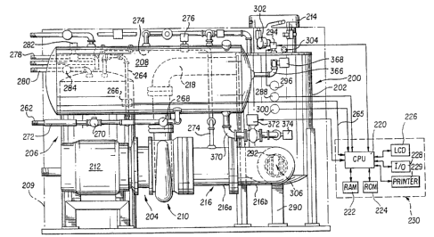
character 200. The system 200 is comprised generally of
a decontamination chamber 202, a waste processing
chopper/pump assembly 204 ('°chopper pump"), a fluid
reservoir 206 for heating and storing a fluid such as
water to be mixed with the waste to be processed, and a
cooling tank 208 for receiving waste processed by the
system and for cooling it prior to disposal. A housing
209 can optionally be provided to enclose the system and
provide acoustic dampening. The chopper/pump 204 is
generally comprised of a grinder ,assembly 210 and a
motor assembly 212 for providing power to the grinder
assembly. A removable cover 214 is provided over an
inlet 215 of the decontamination chamber 202 to permit
user access to the interior of the chamber for deposit-
ing waste to be treated by the processing system 200.
The waste can be in the form of virtually any type of
non-toxic inorganic or organic material, such as medical
waste, food waste, rubber, plastics, and the like for
which it is desirable to disinfect, or optimally render
biologically neutral (i.e., biologically inert or devoid
of living organisms) via sterilization. Medical waste
can include, by way of non-limiting example, sharps such
as needles, knives and blades, trocars, clamps, glass
containers, gauze and bandages, surgical gloves and
gowns, and various other instruments and paraphernalia
which contacts internal body fluids such as blood,
lymphatics, semen and vaginal fluids. Waste steriliz-
ation is preferred in instances such as with some forms
of medical waste where bacteria, viruses and/or spores
may be present, in which case all living organisms
CVO 93/06931 PCT/US92/08219
2~~~~~~
-9-
associated with the waste must be destroyed prior to its
disposal.
The invention is particularly useful for effecting
sterilization of virtually all forms of non-toxic waste
by exposing the waste to superheated water at a tempera
ture in the vicinity of from about 270~F (132~C) to
about 275~F (135~C) at a pressure of from about 55 psi
to about 65 psi, thereby assuring that the fluid is
maintained substantially in a liquid state. Waste
treatment with superheated liquid water as opposed to
water vapor is preferred due to its greater ability to
intermix with the waste solids as they are ground and
circulated by the chopper/pump 204. As will be
described in considerably greater detail below, waste
processing is accomplished by way of a closed,
pressurized circuit which includes the decontamination
chamber 202, pump 204, chopper/pump inlet conduit 216,
grinder assembly 210, and the pump outlet conduit 218
extending between the pump and the decontamination
chamber. Accordingly, each of the circuit components is
formed from suitable materials that are capable of
withstanding the extremes of temperature, pressure and
abrasion that are associated with operation of the waste
processing system of the present invention.
The various aspects of system operation (i.e.,
temperature, pressure, material flow control and the
like) are controlled by a control processor (CPU) 220.
A random access memory (RAM) 222 is electrically
connected to the CPU 220 and stores OSS software and
provides working memory to the CPU. A read-only memory
(ROM) 224 is also provided which stores various programs
that are needed for input/output, power-up, self-test
diagnostics, and the like for the CPU. A display 226
such as a liquid crystal (LCD), light emitting diode
(LED) or cathode ray tube (CRT) display that is operable
to provide human intelligible signal output to a system
operator can optionally be provided. Various input/
CVO 93/06931 ~ Z ~ ~ ~ ~ ~ PCT/US92/08219
-10-
output (I/O) means 228 such as keyboards, switches and
the like are preferably provided to permit user input to
the CPU. A printer 229 can optionally be connected to
the CPU 220 to provide a printout of various data
associated with operation of the waste processing system
200. All of the foregoing electronic components (CPU,
I/o and the like) are preferably provided at a system
control panel 230 that is readily accessible to the
system user.
Waste material to be processed by the system is
deposited in the decontamination chamber through the
chamber inlet 215. As the waste material and water is
to be exposed to relatively high pressure, the cover 214
is configured so as to withstand these pressures and to
prevent inadvertent opening during the course of system
operation. Details of the cover construction are
depicted in Figs. 4 and 5. An oversized handle 232 is
provided which extends across the cover to facilitate
user manipulation of the cover to attain the requisite
level of decontamination chamber sealing. A slot 234 is
provided at four equidistantly-spaced positions along
the side 235 of the cover. Each slot 234 extends away
from a slot opening 236 at the rim 238 of the. cover in
a direction that is counter to the direction of cover
rotation to effect sealing of the decontamination
chamber 202. The slots 234 are dimensioned to receive
therein a corresponding key 240 which extends radially
outwardly from the decontamination chamber outer surface
adjacent to its inlet 215. Due to the rearward inclina-
tion of the slot 234, as the cover is rotated clockwise
(i.e., toward a locked position in the depicted
embodiment), each slot follows its correspondingly
received key 240, resulting in a downward exertion of
pressure by the key 240 against the lower surface 242 of
its corresponding slot.
A sensor 242 is provided along the chamber exterior
adjacent to one of the keys 240. The sensor includes a
w0 93/06931 1~C1'/US92/U82i9
2~~02~4
-11-
plunr~r 246 that is reciprocably extensible with respect
to a censor housing 248. Biasing means such as a spring
(not shown) received within the sensor housing 248
biases the plunger 246 outward from the housing 248 and
into engagement with the cover rim 238. As the cover is
rotatably advanced toward a closed position, the sensor
plunger 246 is advanced into the housing 248 until it
reaches a point within the housing that is commensurate
with complete cover closure, at which point an
electrical signal is emitted from the sensor 230 to the
control processor 220. Upon receipt of the sensor
signal, the processor 220 transmits a signal to a
solenoid 250 near the chamber inlet 215 to effect
extension of a latch 252 from the solenoid housing 254
and into a correspondingly-dimensioned recess 256 formed
in a latch receptacle 258 mounted to the exterior
surface of the side 235 of the cover. Extension of the
latch into the latch receptacle 258 is required before
processing of waste material can proceed so as to ensure
user safety from not only contamination with potentially
infectious waste, but also from physical harm which
could result from exposure to processed waste solids as
they are returned under pressure to the decontamination
chamber 202 following grinding. As a further precau-
tion, the solenoid 250 is of the type which requires
electrical signal input to effect either retraction or
extension of the latch 252. Accordingly, the cover 214
is constructed so as to be incapable of being opened by
ordinary means during the course of waste processing as
well as in the event of a system or power failure during
a material processing cycle, thereby ensuring that the
cover is not opened until processing has been completed.
With reference once again to Figs. 1 through 3,
uncontaminated (i.e., fresh or non-potable) water is
supplied to the reservoir or pre-heat tank 206 via
supply line 262 for subsequent use in the sterilization
process. Water is conveyed from the supply line 262
WU y3/U6931 ~ ~ ~ ~ PCT/US92/08219
-12-
into the pre-heat tank 206 by an inlet pipe 264 when a
control valve 266 such as a solenoid valve positioned in
the inlet pipe 264 (Fig. 2) is biased in an "open"
position. The valve 266, as is the case with all
remotely controllable valves and pumps used in the
system of the present invention, communicate in a
conventional manner with the CPU 220 and receive
operating instructions therefrom as indicated by
communication line 265 (Fig. 1), unless the specifica-
tion explicitly or implicitly provides otherwise. Valve
266 is further operable to effect a pressure reduction
in the incoming water stream from conventional inlet
pressure (typically 60 psi) to about 8 psi. Another
solenoid valve 268 is provided in the supply line 262
downstream from the pipe 264 to control water flow into
the cool-down tank 208. The valves 266 and 268 are
independently operable to provide for the control of
fluid flow into their respective tank. A pressure
relief valve 270 and fluid backflow preventer 272, as
well as various other conventional plumbing apparatus
that are conventionally used in fluid management, are
also provided along the water supply line 262.
The pre-heat tank 206 is preferably in the form of
a large capacity electric or gas-fueled water heater
that is operable in a conventional manner, such as
through the use of a thermostatically controlled burner
or heater assembly, to maintain the stored water at an
elevated, stand-by temperature of about 170~F (77aC) so
as to expedite waste processing in the manner described
below. A conduit 274 extends between the pre-heat tank
206 and the pump inlet conduit 216 to provide for the
delivery of fluid from the pre-heat tank 206 to the flow
of waste material en route to the pump grinder assembly
210 when the system 200 is in operation. Water flow
through the conduit 274 is controlled by a solenoid
valve 276 in accordance with CPU 220 signal output in
the manner described above. A pair of ventilation
v() y3/U6931 1'(;I/US92/U8219
-13-
outlets 278 and 28o extend from the upper end of the
pre-heat tank 206. A solenoid valve 282 is positioned
in the outlet 278 to provide for controlled venting of
pressure within the pre-heat tank 206, whereas
ventilation outlet 280 is provided with a mechanical
pressure-responsive relief valve 284 that is operable in
emergency situations to vent pressure from the tank 206
when the valve's trigger pressure has been attained. As
the valve 284 does not communicate with the CPU 220, it
is isolated from any problems that may arise with system
electronics; instead, it is responsive solely to pres-
sure exerted against it in its associated outlet 280.
The decontamination chamber 202 is configured as a
pressurizable vessel that is capable of withstanding
pressures in the range of from about 55 psi to about 65
psi. The chamber 202 can be formed from any suitable
material that is capable of withstanding the extremes of
temperature, pressure and abrasion that are associated
with operation of the system. Suitable materials
include, by way of example, stainless steel alloys and
high impact, high temperature plastics. Prior to the
commencement of waste processing, pressure within the
decontamination chamber 202 can be equalized with
atmospheric pressure to facilitate filling of the pre-
heat and cool-down tanks 206 and 208. This can be
accomplished by opening the normally closed solenoid
control valve 286 in vent pipe 288 that extends from the
decontamination chamber.
The decontamination chamber is oriented vertically
as shown in the drawings to make use of gravity to
assist in feeding of the waste to the pump assembly 204
and to minimize spatial demands. Tank support legs 290
can be provided to elevate the chamber above the ground
and to position its outlet 292 at the lower end of the
chamber at a level substantially even with that of the
entrance to the pump inlet conduit 216.
CVO 93/06931 1'CT/US92/08219
2?~~i3?~~
-14-
A plurality of heaters 294 are provided at the
upper end of the decontamination chamber 202 to provide
for heating of the water from its elevated base
temperature of about 170~F (77~C) as stored in the
storage tank 206 to the optimal operating temperature of
from about 270~F (132~C) to about 275~F (135~C) during
the course of system operation in the manner set forth
in detail below. The heaters are preferably in the form
of electric resistance immersion heaters having a power
output of about 5,000 watts each. However, the number
and power output of the heaters 294 can be varied in
accordance with such factors as the quantity and
composition (i.e., solid, liquid, plastic, metal and so
on) of the waste that is expected to be typically
processed by a system user, as well as the rate of
processing (i.e., system through-put) that is required
by the user. The temperature and .pressure within the
decontamination chamber is sensed by respective
temperature and pressure sensors 296 and 298, the output
of which is directed to the CPU 220, which is operable
to adjust various system operation parameters in the
manner described below in instances where signal output
from one or both of the sensors 296 and 298 is
indicative of a measured value outside of a range of
prescribed system limits. A further pressure sensor,
designated by reference character 300, is provided with
the decontamination chamber 202 to provide for deactiva-
tion of the fluid heaters 294 in the event that sensed
pressure within the chamber exceeds a predetermined
value. Output from the pressure switch 300 is conveyed
locally rather than through the CPU 220 to the heaters
294 in a manner known in the art (such as by way of
circuit interruption to disable the supply of electric
current to the heaters) to effect their deactivation.
Fluid level sensors 302 and 304 are provided at the
upper end of the decontamination chamber 202 to
respecj~ively monitor fluid levels within the chamber.
1V0 93/06931 1'Cf/U592/08219
-15-
Sensor 302 provides signal output to the control
processor 220 to effect termination of the supply of
water from the hot water tank 206 to the pump inlet
conduit 216 when the decontamination chamber fluid level
reaches a prescribed maximum. Sensor 304 is operable to
provide signal output for deactivating the heaters 294
when the fluid level within the chamber 202 diminishes
below a prescribed level.
As noted above, waste from the decontamination
chamber 202 passes from the chamber outlet 292 to the
chopper/pump assembly 204 through pump inlet conduit
216. Tn the depicted embodiment, the conduit 216 is
comprised of two sections 216a and 216b to accommodate
the lateral displacement of the pump assembly 204
relative to the decontamination chamber; however, a
greater or lesser number of sections can be provided in
accordance with the system design. A gate 306 (Figs. 1
and 6) is provided at the decontamination chamber outlet
292, preferably at the interface between the chamber
outlet and the pump inlet conduit 216, to control the
passage of waste to the pump assembly. The gate 306 is
preferably constructed so that all of its moving parts
are maintained within the sterilization fluid flow in
order to ensure complete sterilization of the gate
during the course of waste processing. With reference
to Fig. 6, the gate 306 is shown as being comprised of
a generally annular gasket 308 that is formed from a
high temperature resistant material such as a "viton"
elastomer. A plurality of apertures 310 are provided
about the annular periphery of the gasket to receive
therethrough appropriate fasteners such as bolts or
rivets (not shown) that are used to secure the gate
between the chamber outlet 292 and the waste conduit
216. A gasket tab 312 extends radially inwardly from a
portion of the gasket 308 to which is secured in a
conventional manner, as by rivets 314 or a suitable
temperature resistant adhesive, a plurality of
V'O 93!06931 PCT/US92/08219
-16-
vertically arrayed bars 316. Because the gate bars 316
are secured to the tab 312 independently of one another,
each is free to independently move to permit for the
passage of waste material through the gate and to the
chopper/pump assembly 204. The gate bars 316 can be
provided with a generally flat or curved surface contour
in their downstream (i.e., facing the viewer) direction
in accordance with user preference to facilitate receipt
within the curved interior of the pump inlet 216. The
bars are formed from a temperature resistant, hardened
material such as stainless steel or any other suitably
hard and temperature and abrasion resistant material and
are spaced up to several mm. apart from one another to
restrict passage of waste solids of a size in excess of
the bar separation distance from passing through the
gate to the pump assembly until the combination of fluid
pressure upstream of the gate 306 (i.e., within the
decontamination chamber 202) and vacuum pressure
developed by operation of the chopper/pump assembly 204
as described below overcomes the inertia provided by the
gate.
The chopper/pump assembly 204 can be of any
suitable design which provides the requisite degree of
waste material processing (i.e., grinding and chopping)
and flow to accomplish the desired objective of process-
ing of waste into relatively small fragments, thereby
increasing its surface area for contact with high
temperature water for effecting disinfection and
optimally sterilization. In preferred aspects of system
operation, the chopper/pump 204 is operable to process
solid waste to a size in the range of from about 1/16
in. (1.5 mm) to about 1/4 in. (6.5 mm) to not only
facilitate its exposure to the heated fluid, but also to
reduce waste volume. The family of horizontal end-
suction chopper pumps manufactured by the Vaughan Co.,
Inc. of Montesano, Washington, such as the model VP3E
pedestal pump, are particularly applicable for use in
WO 93/06931 PCT/US92/08219
-17-
the present invention. Use of this family of pumps is
advantageous, because their respective motors 212 are
oil cooled and lubricated, thereby ensuring that waste-
contaminated water is confined to the prescribed waste
and fluid circulation path. However, other motors which
provide suitable amounts of torque, power, and confine-
ment of the circulated fluid can be used.
With particular reference to Figs. 7 and 8, f~:rther
details of the grinder and motor assemblies 210 and 212
are provided. The motor output shaft 322 extends into
the grinder assembly 210 to provide rotational driving
input (through an appropriate gear reduction assembly
(not shown)) to an impeller 324 that is rotatably
received within a venuri-shaped materials processing
chamber 326. The impeller 324 includes a blade assembly
that is comprised of a pair of generally opposed,
curvalinear cutter blades 328 and 330 that extend from
a hub 332. The hub is fixedly secured to the free end
of the motor output shaft 322 by a retaining plate 334
having an aperture 336 through which extends a
conventional fastener, such as the depicted threaded
fastener 338. The fastener 338 is received within a
complementary-threaded and dimensioned recess 340 formed
in the motor shaft 322.
Fositioned upstream (i.e., to the right side in
Fig. 7) of the cutter blades 328 and 330 is a cutter
plate 342 that is fixedly positioned with respect to the
surrounding grinder housing 344. Alternatively, the
cutter plate and grinder housing can be configured as a
one piece, integral unit. The lower surface 346 of the
cutter plate is provided with a hardened sharpened
surface that is positioned in close proximity to the
rotatably driven cutter blades 328 and 330 to provide
for a compound cutting action of waste material that is
interposed between the blades and the cutter plate
surface. The cutting plate 342 defines a pair of
laterally spaced elongated passages or apertures 348
WO 93/06931 ~, PCT/U592/08219
21~~~:~4
-18-
through which waste material passes for cutting by the
cutting blades 328 and 330. The housing 344 defines a
wall 350 along its medial surface which extends radially
outwardly in the upstream direction so as to guide waste
material and fluid to the cutter blades. Cutting
efficiency is further enhanced by the provision of a
cutter block 352 along a portion of the inner periphery
of the materials processing chamber 326. The radial
inner edge 354 of the cutter block is provided with a
sharpened surface which, together with the fixed cutting
edge 346 of the plate 342, provides for enhanced cutting
efficiency, as waste material is engaged, cut, and
hurled forcefully thereagainst by the rotatably driven
cutter blades 328 and 330. Cutting efficiency can be
further augmented by the provision of an auxiliary
cutting plate 356 (depicted in phantom in Fig. 8)
downstream of the cutter blades which can be provided
with any of a variety of suitable configurations which
supplements the cutting effectiveness of the rotatably
driven blades 328 and 330. The auxiliary plate can be
fixedly secured by threaded fasteners 357 or other
suitable fastening means to the base 358 of the
materials processing chamber 324 as shown, or can be
elevated and supported therefrom by appropriately
dimensioned spacers (not shown) in instances where the
auxiliary cutting plate is provided with cutting
passages of the type described above with reference to
cutting plate 342.
In one aspect of the invention, the motor is
operable to rotate the blades 328 and 330 at a variety
of different speeds (typically in the range of from
about 1700 rpm to about 1900 rpm) in accordance with the
waste composition (i.e., liquids, textiles, metals and
so on) and such user-selectable parameters as flow rate
through the system. Alternatively, a single motor speed
can be provided for processing the waste without regard
to its composition. Waste processing in both schemes of
W() 93/06931 PCT/US92/08219
212~2~~
-19-
operation is to continue for so long as necessary to
ensure that the waste is exposed to superheated water
(i.e., temperature exceeding 270~F (132~C)) for a
minimum of six minutes or longer in instances where
waste sterilization is to be effected, as will be
described in greater detail below. Because a variety of
different types of waste are capable of being handled by
the waste processing system of the present invention,
all cutting surfaces are formed from suitably durable
materials, such as hardened metal alloys and/or metals
provided with a suitable chemical coating in a manner
well known in the field of metallurgy.
With reference again to Figs. 1 through 3, ground
waste material and fluid processed by the grinder
assembly 212 is urged through the materials processing
chamber 326 to the decontamination chamber through
grinder outlet 218, .thereby providing a closed system
for continued waste processing in the manner to be
described below. During the course of system operation,
the fluid heaters 294 are activated to elevate the
temperature of the water and entrained waste material to
the desired operation temperature (from about 270~F
(132°C) to about 275~F (135~C) to effect sterilization)
and the pump 212 is operated for a period in excess of
the requisite period of time that is accepted for
effecting the desired disinfection or sterilization (in
accordance with user instructions) in order to ensure
sterilization of not only the waste material and fluid,
but all of the waste processing hardware with which the
waste and fluid comes into physical contact. The closed
fluid path is maintained at a pressure of from about 55
psi to about 65 psi to ensure that the water introduced
into the system for effecting sterilization maintains
substantially a liquid state of matter. ~s mentioned
above, sterilization with liquid water rather than water
vapor is preferred to ensure full contact and penetra-
tion (where applicable) of waste solids to effect
WO 93/06931 ~ PCT/US92/08219
-20-
sterilization of even compact, porous materials such as
textiles and gauze which can readily absorb potentially
infectious bodily fluids. Excess pressure can be vented
from this closed system into the cool-down tank through
the operation of valves 318 and 319. Valve 318 is
positioned in vent pipe 320 which extends between the
decontamination chamber 202 and the cool-down tank 208
and is in the form of a self-actuating pressure relief
valve that is operable to open and permit communication
between the chamber and tank 208 once its set pressure
has been attained. Valve 319, which is positioned in
line 321 which branches from pipe 220 to the cool-down
tank, is a solenoid valve under the control of the CPU
220 and is operable during the waste material cool-down
cycle described below to release pressure from the
decontamination chamber 202.
Once the prescribed period for,waste sterilization
in the system has passed, the sterilized liquid and
entrained waste solids (collectively referred to as
"waste mixture") are directed to the cool down tank 208
from the decontamination chamber 202 through inlet pipe
366. Flow into the inlet pipe 366 is controlled by
solenoid valve 368, which is ordinarily biased in a
closed position to prevent premature cooling of the
waste material prior to completion of the required
disinfection or sterilization cycle. As the waste
mixture is received within the cool down tank 208, cool
water contained within the tank 208 is admitted into the
decontamination chamber 202 along conduit 370. A fluid
pump 372 is provided in the conduit 370 to supply a
pressurized flow of cooling water to the decontamination
chamber. A valve 374 such as a ball valve is provided
in the conduit to ensure unidirectional fluid flow into
the decontamination chamber once the pump 372 has been
activated. As the waste mixture is circulated by the
pump assembly 204 throughout the closed system and cool
down tank, the mixture is cooled from the temperature
~V() 93/06931 ~ ~ ~ (~ ~ ~ ~ f'CT/US92/0$219
-21-
that was necessary to ensure the desired disinfection or
sterilization to a temperature which satisfies any
prevailing municipal requirements for waste disposal
into, for example, a municipal sewer system. Once the
temperature of the cooled waste mixture has diminished
to the requisite disposal temperature, it is directed by
' the operation of pump 372 from the cool down tank, upon
opening of solenoid valve 378, through a disposal
conduit 376 (Fig. 2) for removal from the processing
system. Preferably, the waste solids are separated from
the liquid, as can be accomplished by filtration through
filter assembly, depicted in phantom and denoted
generally by reference character 380, prior to disposal,
thereby reducing by several orders of magnitude the
volume of waste solids to be disposed for many waste
materials.
System operation
The operation of the waste processing system 200 of
the present invention will now be described with
reference to the flow diagram illustrated in Figs. 9A
and 9B, with concurrent reference to Figs. 1 through 3.
Waste to be processed is deposited in the
decontamination chamber 202 and the lid 214 therefor is
closed and sealed. Priar to the commencement of waste
processing, the CPU 220 is operable in accordance with
program control from RAM to run a self-diagnostic check
of the system electricals and electrically-operated
components such as various valves and temperature and
pressure sensors which communicate with the CPU,, as
indicated by block 384 in the flow chart. Communication
between such electrically operable components and the
CPU is indicated in Fig. 1 by a communication line
extending between the controlled part and the CPU. An
example of such a communication line is provided by line
265 which extends between valve 266 and the CPU 220. It
is to be understood, however, that similar. communication
WO 93/06931 ~ ~ ~ ~ ~ C~ ~~ PCT/US92/08219
-22-
lines exist between the CPU 220 and each part with which
the CPU communicates, either in a unidirectional or a
bi-directional manner. For the sake of clarity, however,
such lines have not been included in Fig. 1, but they
are understood to be present in order to provide the
requisite control for system operation as described
previously and below.
Upon successful completion of the self-diagnostic
test, the CPU 220 receives signal input from a tempera
ture sensor included with the pre-heat tank 206 that
provides an indication of the temperature of fluid
within the tank, as indicated by decision block 386. In
instances where fluid temperature is below prescribed
system operating limits for the system 200, as may be
the case when the tank has recently been replenished
with tap water, a "default" message conveying to the
system user the unreadiness of the system to commence
operation is produced in the display 226, as indicated
by block 388, and the heating elements included with the
tank are switched on to bring the fluid stored within
the tank to operating temperature, noted by block 390.
In instances where the pre-heat tank fluid tempera-
ture meets the pre-established operating temperature,
the CPU 220 is then commanded to analyze input from the
decontamination chamber cover solenoid 254 (Fig. 5) to
determine whether or not the cover 214 has been properly
sealed, as shown by block 392. An appropriate default
message such as "close cover" (block 394) is generated
for display to the user via console display 226 in
instances where output from the solenoid 254 to the CPU
220 along an appropriate communication line (not shown)
is indicative of incomplete cover closure. If the
output from the solenoid 254 is of a character that
confirms cover closure and sealing, the CPU 220 is
operable to communicate with the various valves and
pumps under its control to confirm their respective
proper orientation (i.e., "closed" or "open") prior to
WO 93/06931 I'Cf/US92/08219
2
-23-
commencement of system waste handling (block 396) and to
adjust the valves accordingly in instances where the
valve position or pump operation status communicated to
the CPU 220 does not comply with the system operating
program stored in RAM 222.
once the foregoing system operation statuses have
been confirmed and corrected as required, the CPU 220 is
operable to deliver signal input to the chopper/pump
assembly 204 to effect chopper/pump operation at the
prescribed rate of speed (block 398) and to deliver
signal input to the valve 276 to permit a flow of heated
fluid from the pre-heat tank 206 to the pump inlet
conduit 216 (block 400). Fluid delivered from the tank
206 is conveyed by the chopper/pump 204 to the decon-
tamination chamber 202 through pump outlet 2.18, where
the fluid mixes with the waste ,material deposited
therein. Once fluid pressure within the decontamination
chamber 202, in combination with the negative pressure
exerted by the chopper/pump 204, exceeds the inertia of
the waste gate 306, waste solids pass with the fluid
flow to the chopper/pump grinder assembly 210, where
they are chopped and ground by the rotating cutter
blades 329 and 330 and cooperating cutting surfaces of
the cutter plates) 342 and 356, and conveyed into
outlet 218 for recirculation to the decontamination
chamber 202. Fluid level sensor 302 provides signal
output to the CPU to convey the fill status of the
decontamination chamber as water is delivered from the
pre-heat tank into the circulating stream of water and
liquid and solid waste material in the manner described
above.
As the fluid and waste mixture is circulated
between the decontamination chamber and chopper/pump
through the respective pump inlet and outlet conduits
216 and 218, the CPU 220 is operable to activate the
decontamination chamber heaters 294 to elevate the
temperature of the circulating stream to the operating
WO 93/0G931 ~ ~ 2 ~ ~ C~ ~ PCT/US92/08219
-24-
temperature that is required to effect the selected
level of processing. In this regard, a temperature in
the range of 270~F is to be maintained for a continuous
period of at least six minutes to effect waste
sterilization, whereas a lesser temperature on the order
of at least about 212~F is preferred for disinfection.
Temperature data from the decontamination chamber is
conveyed by sensor 296 to the CPU, which continues
signal output to the heaters 294 (block 404) until the
fluid temperature as sensed by sensor 296 reaches the
desired operating temperature. once this temperature
has been attained, a timer (not shown) such as that
typically provided for CPU operation is started, as
noted by block 406. Additionally, a printer, which can
optimally be provided with the system to document such
system parameters as fluid temperature, is also actuated
(block 408).
As the waste processing cycle continues in the
foregoing manner, the CPU is operable to compare clock
and temperature sensor 296 output data with the
preselected time and temperature parameters stored in
CPU memory to allow for determination of whether the
required time of material processing at the requisite
temperature set forth in the CPU operating program has
lapsed (block 410). This comparison process continues
until the clock and temperature data provided to the CPU
220 indicate that the requisite period has passed, at
which time the printer is deactivated (block 412) and
the CPU is operable to cool the water and entrained
waste solids and liquids ("waste mixture").
The CPU 220 implements cooling of the waste mixture
by directing valve 374 in the cooling tank conduit 370
to open and pump 372 to commence pumping of cool (i.e.,
ambient temperature or chilled) water into the decon-
tamination chamber 202, as indicated by block 416. The
CPU 220 also commands valve 368 in inlet 366 to open,
thereby admitting a portion of the circulating waste
WO 93/06931 ~ ~ PCT/US92/08219
-25-
mixture with the cool-down tank 208. The CPU monitors
the temperature of the circulating waste mixture (block
418) and continues to supply cool water until the tem-
perature diminishes to the desired level for disposal.
The desired cooling temperature may, for example, be
that temperature established by municipalities at which
qualifying waste material can be passed into the sewer
or other municipal disposal system. Once the
temperature has reached the requisite cool-down
temperature, the CPU 220 directs waste valve 378 in
disposal conduit 376 to open (block 420), thereby
allowing for the disposal of the cooled waste mixture
from the cool-down tank 206. Waste solids in excess of
a predetermined size can optionally be filtered from the
waste mixture passing through the disposal conduit to
permit its disposal apart from the liquid component of
the waste mixture. Such waste solids, by virtue of
having been processed in the foregoing manner, can be
disposed of in a conventional manner in a compact form,
thereby lessening the burden on waste disposal facili-
ties and on the waste originator in providing for safe
and efficient waste disposal. The CPU is operable
thereafter to provide for refilling of the respective
pre-heat and cool-down tanks to replenish their supplies
of water used in the foregoing processing cycle. Tank
refilling is accomplished as a result of CPU signal
input to valves 266 and 268 directing their respective
opening, thus allowing for replenishment of associated
pre-heat and cool-down tanks 206 and 208 with fresh
water for use in a subsequent waste processing cycle.