Language selection

Search

Patent 2120572 Summary

Third-party information liability

Some of the information on this Web page has been provided by external sources. The Government of Canada is not responsible for the accuracy, reliability or currency of the information supplied by external sources. Users wishing to rely upon this information should consult directly with the source of the information. Content provided by external sources is not subject to official languages, privacy and accessibility requirements.

Claims and Abstract availability

Any discrepancies in the text and image of the Claims and Abstract are due to differing posting times. Text of the Claims and Abstract are posted:

  • At the time the application is open to public inspection;
  • At the time of issue of the patent (grant).
(12) Patent: (11) CA 2120572
(54) English Title: PROSTATIC STENT
(54) French Title: DRAIN PROSTATIQUE
Status: Deemed expired
Bibliographic Data
(51) International Patent Classification (IPC): N/A
(72) Inventors :
  • MIKULICH, MICHAEL (Switzerland)
  • CLERC, CLAUDE (Switzerland)
  • JEDWAB, MICHAEL (Switzerland)
  • FURRER, ADRIAN (Switzerland)
  • MARILLER, ALAIN (Switzerland)
  • BURTON, JOHN (United States of America)
  • TIHON, CLAUDE (United States of America)
(73) Owners :
  • AMS MEDINVENT S.A. (Switzerland)
(71) Applicants :
(74) Agent: SMART & BIGGAR
(74) Associate agent:
(45) Issued: 1998-07-14
(22) Filed Date: 1994-04-05
(41) Open to Public Inspection: 1994-10-28
Examination requested: 1994-04-05
Availability of licence: N/A
(25) Language of filing: English

Patent Cooperation Treaty (PCT): No

(30) Application Priority Data:
Application No. Country/Territory Date
9301415-7 United States of America 1993-04-27

Abstracts

English Abstract


A prostatic stent having an elongate body (13)
defining a passage therethrough and comprising a distal
section (17), a mid-section (19) and a proximal section (21),
said elongate body (13) having a length sufficient to
extend distally from a bladder neck (3) to a position
somewhat short of the external sphincter (9), and said proximal
section (21) having a shape conforming to the neck (3)
of the urinary bladder (l); and
processes for the manufacture of such prostatic stent
of a metallic braided type.


French Abstract

La présente invention porte sur un tuteur prostatique ayant un corps allongé (13) traversé d'un passage et comprenant une section distale (17), une section intermédiaire (19) et une section proximale (21). Ledit corps allongé (13) est de longueur suffisante pour se prolonger du col vésical (3) jusqu'à proximité du sphincter externe (9) et la forme de la section proximale (21) est adaptée à la forme du col (3) de la vessie urinaire (1). Sont également décrits les procédés utilisés pour fabriquer un type de tuteur prostatique métallique tressé.

Claims

Note: Claims are shown in the official language in which they were submitted.


THE EMBODIMENTS OF THE INVENTION IN WHICH AN EXCLUSIVE
PROPERTY OR PRIVILEGE IS CLAIMED ARE DEFINED AS FOLLOWS:


1. A prostatic stent having an elongate body defining a
passage therethrough and comprising a distal section, a
mid-section and a proximal section, said elongate body having
a length sufficient to extend distally from urinary bladder
neck to a position somewhat short of the external sphincter,
and said proximal section terminating in a proximal end which
extends in a plane sloping at an angle to a normal to a center
line of said body whereby said proximal section exhibits a
shape conforming to the neck of the urinary bladder.


2. A prostatic stent according to claim 1, wherein
said angle does not exceed 50°.


3. A prostatic stent according to claim 2, wherein said
angle lies within a range of 5 to 40°.


4. A prostatic stent according to claim 3, wherein
said angle lies within a range of 10 to 300°.


5. A prostatic stent according to claim 1, 2, 3 or 4,
wherein said mid-section has a substantially constant
cross-section along said mid-section.


6. A prostatic stent according to claim 1, 2, 3, 4 or

11

5, wherein said proximal section of the body has a flare
conforming to the tapered neck of the bladder.


7. A prostatic stent according to claim 1, 2, 3, 4, 5
or 6, wherein said distal section of the body has a distally
directed flare to prevent proximal migration of the stent and
to conform to the surrounding urethral wall.


8. A prostatic stent according to claim 1, 2, 3, 4, 5
or 6, wherein said distal section of the body has a
distally directed taper so as not to interfere with the
sphincter function.


9. A prostatic stent according claim 1, 2, 3, 4, 5, 6,
7 or 8, wherein said body has an approximately circular radial
cross-section.


10. A prostatic stent according to claim 1, 2, 3, 4, 5,
6, 7 or 8, wherein said body has a non-circular radial
cross-section for improved conformation to the surrounding urethral
wall.


11. A prostatic stent according to claim 10, wherein
said non-circular radial cross-section has a flattened or oval
shape.


12. A prostatic stent according claim 1, 2, 3, 4, 5, 6,

12

7, 8, 9, 10 or 11, which is of a self-expandable type.


13. A prostatic stent according to claim 12, which is of
the braided type comprising a flexible tubular body which has
a diameter that is variable by axial movement of the ends of
the body relative to each other and which is composed of
several individual rigid but flexible thread elements each of
which extends in helix configuration with the center line of
the body as a common axis, a number of elements having the
same direction of winding but being axially displaced relative
to each other crossing a number of elements also axially
displaced relative to each other but having the opposite
direction of winding.


14. A prostatic stent according to claim 13, wherein
said proximal end of said body extends in a plane that is
substantially parallel to the oppositely extending filaments
in the stent.


15. A prostatic stent having an elongate body defining a
passage therethrough, and comprising a proximal section having
a flaring and oblique proximal end conforming both radially
and axially to the walls of the surrounding bladder neck,
further comprising a mid-section having a substantially
constant cross-section along said mid-section and a distal
section, said elongate body having a length sufficient to
extend distally from a bladder neck to a position short of the


13

external sphincter.


16. A prostatic stent according to claim 15, which is of
a self-expandable type.


17. A prostatic stent according to claim 16, which is of
the braided type comprising a flexible tubular body which has
a diameter that is variable by axial movement of the ends of
the body relative to each other and which is composed of
several individual rigid but flexible thread elements each of
which extends in helix configuration with the center line of
the body as a common axis a number of elements having the
same direction of winding but being axially displaced relative
to each other crossing a number of elements also axially
displaced relative to each other but having the opposite
direction of winding.


18. A process for the manufacture of a metallic braided
prostatic stent having an elongate body defining a passage
therethrough, and comprising a proximal section having a
flaring and oblique proximal end conforming both radially and
axially to the walls of the surrounding bladder neck, further
comprising a mid-section having a substantially constant
cross-section along said mid-section and a distal section,
said process comprising the steps:

a) preparing a braided hollow, deformable body having
substantially straight cylindrical walls;


14

b) mounting the body resulting from step a) onto a
mandrel with a shape corresponding to the desired shape of the
finished stent;
c) applying energy or external pressure or both onto
said body positioned on said mandrel to cause said body to
conform to the shape of the mandrel;
d) removing the thus shaped body from the mandrel; and
e) cutting the proximal end to the desired obliqueness.


19. A process for the manufacture, from a plurality of
filaments, of a metallic braided prostatic stent having an
elongate body defining a passage therethrough, and comprising
a proximal section having a flaring and oblique proximal end
conforming both radially and axially to the walls of the
surrounding bladder neck, further comprising a mid-section
having a substantially constant diameter, and a distal
section, said process comprising the steps:
a) providing a braiding bar with a shape corresponding
to the shape of the finished stent;
b) preparing a braided body by performing the braiding
of the filaments on said braiding bar;
c) removing said braided body from said braiding bar,
optionally after the application of energy and/or pressure of
said body while placed on said bar; and
d) cutting the proximal end to the desired obliqueness.


15

20. A process for the manufacture, from a plurality of
filaments, of a metallic braided prostatic stent having an
elongate body defining a passage therethrough, and comprising
a proximal section having a flaring and oblique proximal end
conforming both radially and axially to the walls of the
surrounding bladder neck, further comprising a mid-section
having a substantially constant diameter, and a distal
section, said process comprising the steps:
a) providing a braiding bar, the radial cross-section
of which is substantially constant along its entire length;
b) preparing a braided body by performing the braiding
at varying axial speed of said braiding bar to obtain a
varying angle between the crossing filaments along said bar;
c) mounting the body resulting from step b) onto a
mandrel with a shape corresponding to the desired shape of
the finished stent;
d) applying energy and/or pressure to said body when
placed on said mandrel to cause said body to conform to
the shape of the mandrel and removing the thus shaped body
from the mandrel; and
e) cutting the proximal end to the desired obliqueness.


Description

Note: Descriptions are shown in the official language in which they were submitted.


2120~72


Prostatic stent

Technical field
The present invention relates to a prostatic stent
comprising an elongate body which defines a passage there-
through, and the invention also covers processes for the
manufacture of such prostatic stent made of a metallic ma-
terial.
Thus, the invention more specifically relates to a
prostatic stent for non-surgical treatment of obstruction
of prostatic urethra, such as may arise in connection with
benign prostatic hyperplasia or prostatic carcinoma.

Background of the invention
A commonly occurring disorder in urology is the ob-
struction of prostatic urethra. The disorder occurs in
males due to enlargement of the prostatic gland, due to
either hyperplasia or cancer. A condition ofter. found in
older males is known as benign prostatic hyperplasia
(BPH), and said condition can cause a plurality of incon-
venient symptoms, such as difficulties to urinate, strong-
ly reduced capacity to urinate, and the condition may at
times result in complete retention of urine which may lead
to severe renal disorders.
The traditional procedure for treating problems asso-
ciated with enlargement of the prostate gland has up to
now been surgery constituted by cutting away interior sec-
tions of the prostate gland or complete surgical removal
of the prostate. These are, however, procedures unfavoured
by many patients and there has been a search for alterna-
tive ways of dealing with the problem.
US patent 5,059,169 is an example of such alternative
to surgery. Said patent discloses a prostatic stent pro-
vided with a conical flange disposed within the neck of
the bladder, the opposite end of the stent body extending
approximately to the verumontanum. The stent is provided
with a textured exterior surface that frictionally engages

212~572


the urethral walls to prevent migration of the stent into
the bladder. Migration in the opposite direction is pre-
vented by the conical flange.
However, this prior art high-friction prostatic stent
is associated with disadvantages, in particular at and
around the conical flange disposed within the neck of the
bladder due to the fact that said end of the stent does
not conform to the bladder neck in view of the fact that
the proximal end of the stent is designed perpendicular to
a center line of the body of the stent. This design means
that the stent cannot be placed optimally to cover the
complete bladder neck. Either it causes urinary stones
(calculi, encrustation) to form on the device protruding
into the bladder or the device does not completely cover
the circumference of the bladder neck when the stent is
placed further down the prostatic urethra running the risk
of not relieving the obstruction.

Summary of the invention
One object of the present invention is to provide an
improved prostatic stent for the treatment of bladder out-
let obstruction caused by an enlarged prostate.
Another object of the present invention is to provide
a prostatic stent having a shape conformed to the neck of
the urinary bladder to avoid urinary calculi or encrusta-
tion or to avoid uncovered areas of the prostatic urethra
adjacent to the bladder neck.
Still another object of the invention is to provide a
prostatic stent while avoiding migration of the stent into
the bladder or distally towards the sphincter.
Yet another object of the invention is to provide
processes for the manufacture of metallic braided pros-
tatic stents showing improved performance when used for
solving the problem of non-surgical management of bladder
outlet obstruction.

7 2


Other objects and advantages of the present invention
will be understood upon reading of the following disclo-
sure taken together with the drawing and the appended
~ claims.
Thus, the invention resides in a prostatic stent
having an elongate body defining a passage therethrough
and comprising a distal section, a mid-section and a
proxima-l section, said elongate body having a length suf-
ficient to extend distally from the bladder neck to a po-
sition somewhat short of the external sphincter, such as
up to and/or passing the verumontanum, and said proximal
section having a shape conforming to the neck of the uri-
nary bladder.
In order to conform to the neck of the urinary blad-
der it is preferred that the proximal end of said proxima~section extends in a plane sloping at an angle to a normal
to a center line of the body not exceeding about 50~. It
is particularly preferred that said angle lies within the
range of about 5 to about 40~, such as within a range of
about 10 to about 30~.
In a preferred embodiment of the invention said mid-
section has a substantially constant cross-section along
said mid-section, i.e. said cross-section has a cross-
sectional area and shape that are substantially constant
along said section.
In order that the prox;m~l section shall have a shape
conforming to the neck of the urinary bladder it is pre-
ferably provided with a flare conforming to said tapered
neck.
As indicated above the prostatic stent of the inven-
tion extends to the bladder neck up to a position at least
short of the verumontanum and it can extend all the way up
to short of the sphincter. It is, of course, important
that the stent extends short of the sphincter so as not to
3~ interfere with the normal function of the sphincter. In
embodiments where the stent extends to a position short of
the sphincter and adjacent to the verumontanum it is pre-


2 1 205 72


ferred that the body has a distally dlrected flare to preventproxlmal mlgratlon of the stent thereby conformlng to the
surroundlng urethral wall. On the other hand, ln embodlments
where the stent extends beyond the verumontanum and up to a
posltlon short of the sphlncter, lt ls preferred that the body
has a dlstally dlrected taper so as not to lnterfere wlth the
sphlncter function.
In the lnstant dlsclosure the term "dlstal" or
"dlstally" refers to a dlrectlon from the lnslde of the
patlent body to the exterlor thereof, whereas the term
"proxlmal" or "proxlmally" refers to the opposlte dlrectlon.
The prostatlc stent accordlng to the lnventlon may
have an approxlmately clrcular radlal cross-sectlon, or lt
may have a non-clrcular radlal cross-section for lmproved
conformation to the surroundlng urethral wall. In the latter
case sald non-clrcular radlal cross-sectlon may be of a
flattened or oval shape.
It ls preferred that the prostatlc stent accordlng
to the lnvention ls of a self-expandable type. An example of
partlcularly preferred self-expandable stent ls found ln US
patent 4,655,771. Such stent ls thus of the bralded type
comprlslng a flexlble tubular body whlch has a dlameter that
ls varlable by axlal movement of the ends of the body relatlve
to each other and whlch ls composed of several lndlvldual
rlgld but flexlble thread elements or fllaments each of whlch
extends ln hellx conflguratlon wlth the center llne of the
body as a common axls, a number of elements havlng the same


74837-4
A

2 1 2 0 5 7 2


dlrectlon of wlndlng but belng axially dlsplaced relatlve to
each other crosslng a number of elements also axially
dlsplaced relative to each other but having the opposite
dlrectlon of wlndlng.
In a particularly preferred embodlment of such
prostatlc stent the proxlmal end of the body extends ln the
plane that ls substantlally parallel to the opposltely
extendlng fllaments in the stent.
A preferred embodiment of the invention resides ln a
prostatlc stent havlng an elongate body deflnlng a passage
therethrough, and comprlslng a proxlmal sectlon havlng a
flarlng and obllque proxlmal end conformlng both radlally
and axlally to the walls of the surroundlng bladder neck,
further comprlsing a mld-sectlon havlng a substantlally
constant cross-sectlon along sald mld-sectlon, and a dlstal
sectlon, sald elongate body havlng a length sufflclent to
extend dlstally from a bladder neck to a posltion somewhat
short of the external sphincter.
The invention also resides in a process for the
manufacture of a metallic braided prostatic stent as disclosed
above, said process comprising the steps:
a) preparing a braided hollow, deformable body having
substantially straight cylindrical walls;
b) mounting the body resulting from step a) onto a
mandrel with a shape corresponding to the desired shape of the
finished stent;
c) applying energy or external pressure or both onto


74837-4


sald body posltloned on sald mandrel to cause sald body to
conform to the shape of the mandrel; and
d~ removlng the thus shaped body from the mandrel.
In an alternatlve process of the lnventlon for the
manufacture of the metallic bralded prostatlc stent the steps
lnvolved are the followlng:
a) provldlng a braldlng bar wlth a shape correspondlng
to the shape of the flnished stent;
b) preparlng a bralded body from a plurallty of
fllaments by performlng the braldlng of the fllaments on sald
braldlng bar; and
c) removlng sald braided body from sald braiding bar,
optlonally after the application of energy and/or pressure of
said body whlle placed on sald bar.
In yet an alternatlve process of the lnventlon for
the manufacture of a metalllc bralded prostatlc stent, the
process comprlses the steps:
a) provldlng a braiding bar, the radial cross-sectlon
of whlch ls substantlally constant along its entire length;
b) preparing a braided body from a plurality of
filaments by performlng the braldlng at varying axial speed of
sald bralding bar to obtaln a varying angle between the
crossing filaments along sald bar; and
c) mountlng the body resultlng from step b) onto a
mandrel wlth a shape correspondlng to the deslred shape of
the flnlshed stent; and
d) applylng energy and/or pressure to sald body when


1 74837-4

2 1 20S 72


placed on said mandrel to cause said body to conform to the
shape of the mandrel and removing the thus shaped body from
the mandrel.
In the previously described embodlment, the varying
angle between the crossing filaments of the braided body
produced on the braiding bar is required to produce a finished
stent in which the angle between the crossing filaments ls
substantially constant along the full length of the stent,
including the flaring upper part thereof. When braiding the
body which will constitute the stent on a braiding bar which
has a radial cross-section that is substantially constant
along its entire length, the angle between the crossing
filaments must be different in the section corresponding to
the flaring part of the flnlshed stent. In thls case the
angle between the crosslng fllaments must be greater ln the
section of the braided body corresponded to the flaring
portion of the finished stent so that the angle will be
constant after the finished shaping of the stent in accordance
wlth steps c) and d). Such greater angle in the section
corresponding to the flaring portion of the flnlshed stent ls
achieved by lncreasing the axial speed of the braiding bar
when the braiding is performed on this section of the braided
body in order to ultlmately produce a flnished stent ln whlch
the angle between the crosslng filaments is substantially
constant throughout the length of the flnished stent.
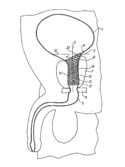
Brlef description of the drawing
The enclosed drawing is a perspective view ln cross-


74837-4

~1 20572


sectlon in a saglttal plane showing the urlnary tract and
bladder and the prostatlc stent accordlng to the lnventlon in
an lmplanted posltlon wlthln the urethral tract.
Detailed descrlptlon of the disclosed embodlment
Wlth reference to the drawlng there ls shown ln a
dlagrammatlc manner a cross-sectlon ln a saglttal plane of
the area surroundlng the urlnary tract lncludlng the bladder.
In the drawlng, there ls shown the bladder 1 havlng a
tapered neck 3. The bladder neck 3 tapers lnto the urethra
5, and the prostatlc part 11 of the urethra 5, approxlmately 3
to 4 cm thereof, ls surrounded by the prostate gland 7. In the
drawlng there ls also dlagrammatlcally shown the external
sphlncter 9, whose normal functlon ls to keep the urethra
closed untll urlnatlon when lt opens for emptylng the bladder
1. On the rear wall of the urethra 5 (more partlcularly the
upper portlon 11 thereof) there ls a small pro~ectlon, the
verumontanum 10.
Shown ln an lmplanted posltlon ln the upper part of
urethra 5 a stent 13 ln accordance wlth the lnventlon ls
placed. Sald sections 17,19,21 form an elongate body 13
constltutlng the stent proper. A center llne L through
sald elongate body 13 ls shown ln the drawing.
The embodlment of the stent 13 shown ln the drawing
ls deslgned ln accordance with the prosthesis for translumlnal
lmplantatlon dlsclosed ln US patent 4,655,771. For detalls
regardlng thls type of stent reference ls made to the
dlsclosure of sald US patent. It ls preferred that the stent


74837-4

~ l 2051~
7b
is made of a materlal possesslng sprlnglness or aglllty
comblned wlth sultable elastlcity. A preferred material is a
medlclnally acceptable metal, for example Phynox*, Elglloy*,
MP35N or tltanlum.
The proxlmal end 23 of stent 13 ls designed to
conform to the neck 3 of the urlnary bladder 1. As shown ln
the drawing the plane P of the proximal end 23 of stent 13
has a sloplng extenslon under an angle a to the normal N to
the center line L of the elongate stent body. Thls sloping
extension of proximal end 23 results in a stent
configuration closely conforming to the surroundlng neck 3 of
bladder 1 resultlng in advantages to be explalned below.
In the embodiment shown in the drawlng the dlstal
section 17 of stent 13 extends up to a positlon short of
sphlncter 9 and has a dlstally dlrected taper so as not to
interfere wlth the sphlncter functlon. Sald dlstal sectlon 17
of the stent may also extend to a positlon somewhat short of
the verumontanum 10 and ls then preferably provlded wlth a
dlstally dlrected flare for the purpose of preventlng proxlmal
mlgratlon of the stent and also to conform to the surrounding
urethral wall.
The procedure for preparlng for lmplantation and the
implantation proper wlll now be described in some detall.


* Trademark


74837-4

~1 ~(J5~'
7c
In order to select the correct size of the prostatic
stent the urologist determlnes the length of the prostatlc
urethra. The length of the prostatic urethra from the


74837-4

2120572

bladder neck to the verumontanum or to the sphincter, res-
pectively, can be determined by using a measuring cathe-
ter. The measures taken up to this point are largely con-
ventional to the skilled urologist.
After selection of the appropriate stent size due
consideration being taken of the fact that the stent must
be shorter than the measured'length of the prostatic ure-
thra to allow for the natural elongation of the stent in
response to the pressure of the enclosing urethral walls,
the prostatic stent applied to a suitable delivery instru-
ment is then inserted into the prostatic urethra via penis
and the urethral tract to the position shown in the draw-
ing. It is important to note that the sloping end 23 of
the stent 13 has the orientation shown in the drawing,
i~e. the slope being directed to be at a maximum in the
direction of the sagittal plane through the center line L
of the stent body 13.
It is important to note that the prostatic stent does
not extend into the external sphincter because such posi-
tion of the stent will cause incontinence to the patient.After proper positioning of the stent the stent is relea-
sed from the implantation instrument, and the instrument
is withdrawn and removed from the patient.
The feature of the proximal section 21 of the stent
13 being designed with a shape conforming to the neck 3 of
the urinary bladder 1 results in important advantages in
practical use of the stent. Thus, as is understood from
the drawing, the conformed shape of the proximal end 23 of
the proximal section 21 of stent 13 means that urinary
calculi or encrustation cannot accumulate on ~he stent due
to the fact that it fits snugly to the interior of the
neck 3 of bladder 1 and becl~ es covered with tissues after
implantation. Nor will there be uncovered parts on the
other side of the stent. The stent will perform its ope-
ning and supporting functions all the way to the entirebladder neck without allowing wires to protrude into the
bladder which could become calcified. Furthermore, the

q. ~


proximal flare of the proximal section 21 of the stent
prevents the stent from distal migration towards the
sphincter 9. On the other hand, in embodiments where the
distal section 17 of the stent has a distally directed
flare proximal migration of the stent into the bladder
will be prevented.
It is to be noted that the invention is not to be
limited to the exact details of constructional features or
other aspects as shown and described, as obvious modifi-
cations of equivalence will be apparent to the skilledartisan, and the invention is therefore to be limited only
by the scope of the appended claims, including the appli-
cation of the doctrine of equivalence theretoO


Representative Drawing
A single figure which represents the drawing illustrating the invention.
Administrative Status

For a clearer understanding of the status of the application/patent presented on this page, the site Disclaimer , as well as the definitions for Patent , Administrative Status , Maintenance Fee  and Payment History  should be consulted.

Administrative Status

Title Date
Forecasted Issue Date 1998-07-14
(22) Filed 1994-04-05
Examination Requested 1994-04-05
(41) Open to Public Inspection 1994-10-28
(45) Issued 1998-07-14
Deemed Expired 2010-04-06

Abandonment History

There is no abandonment history.

Payment History

Fee Type Anniversary Year Due Date Amount Paid Paid Date
Application Fee $0.00 1994-04-05
Registration of a document - section 124 $0.00 1994-09-16
Maintenance Fee - Application - New Act 2 1996-04-05 $100.00 1996-03-14
Maintenance Fee - Application - New Act 3 1997-04-07 $100.00 1997-03-14
Final Fee $300.00 1998-01-29
Maintenance Fee - Application - New Act 4 1998-04-06 $100.00 1998-03-23
Maintenance Fee - Patent - New Act 5 1999-04-05 $150.00 1999-03-09
Maintenance Fee - Patent - New Act 6 2000-04-05 $150.00 2000-03-22
Maintenance Fee - Patent - New Act 7 2001-04-05 $150.00 2001-03-23
Maintenance Fee - Patent - New Act 8 2002-04-05 $150.00 2002-03-19
Maintenance Fee - Patent - New Act 9 2003-04-07 $150.00 2003-03-19
Maintenance Fee - Patent - New Act 10 2004-04-05 $250.00 2004-03-17
Maintenance Fee - Patent - New Act 11 2005-04-05 $250.00 2005-03-16
Maintenance Fee - Patent - New Act 12 2006-04-05 $250.00 2006-03-16
Maintenance Fee - Patent - New Act 13 2007-04-05 $250.00 2007-03-16
Maintenance Fee - Patent - New Act 14 2008-04-07 $250.00 2008-03-25
Owners on Record

Note: Records showing the ownership history in alphabetical order.

Current Owners on Record
AMS MEDINVENT S.A.
Past Owners on Record
BURTON, JOHN
CLERC, CLAUDE
FURRER, ADRIAN
JEDWAB, MICHAEL
MARILLER, ALAIN
MIKULICH, MICHAEL
TIHON, CLAUDE
Past Owners that do not appear in the "Owners on Record" listing will appear in other documentation within the application.
Documents

To view selected files, please enter reCAPTCHA code :


To view images, click a link in the Document Description column. To download the documents, select one or more checkboxes in the first column and then click the "Download Selected in PDF format (Zip Archive)" or the "Download Selected as Single PDF" button.

List of published and non-published patent-specific documents on the CPD .

If you have any difficulty accessing content, you can call the Client Service Centre at 1-866-997-1936 or send them an e-mail at CIPO Client Service Centre.


Document
Description 
Date
(yyyy-mm-dd) 
Number of pages   Size of Image (KB) 
Drawings 1995-04-14 1 38
Cover Page 1995-04-14 1 58
Abstract 1995-04-14 1 27
Claims 1995-04-14 5 274
Description 1995-04-14 9 546
Description 1997-08-07 12 439
Claims 1998-06-01 6 188
Description 1998-06-01 12 439
Claims 1997-08-07 6 188
Cover Page 1998-07-10 1 43
Claims 1998-05-22 6 188
Description 1998-05-22 12 439
Representative Drawing 1998-07-10 1 10
Correspondence 1998-01-29 1 32
Prosecution Correspondence 1997-07-17 5 188
Examiner Requisition 1997-01-17 3 112
Fees 1998-03-23 1 33
Fees 1997-03-14 1 31
Fees 1996-03-14 1 49