Language selection

Search

Patent 2120787 Summary

Third-party information liability

Some of the information on this Web page has been provided by external sources. The Government of Canada is not responsible for the accuracy, reliability or currency of the information supplied by external sources. Users wishing to rely upon this information should consult directly with the source of the information. Content provided by external sources is not subject to official languages, privacy and accessibility requirements.

Claims and Abstract availability

Any discrepancies in the text and image of the Claims and Abstract are due to differing posting times. Text of the Claims and Abstract are posted:

  • At the time the application is open to public inspection;
  • At the time of issue of the patent (grant).
(12) Patent: (11) CA 2120787
(54) English Title: WALL MOUNTED PIPE CLAMP
(54) French Title: COLLIER DE FIXATION DE TUBES A MONTAGE MURAL
Status: Deemed expired
Bibliographic Data
(51) International Patent Classification (IPC):
  • B25B 5/00 (2006.01)
  • B25B 5/06 (2006.01)
(72) Inventors :
  • SCHNELL, MARK (United States of America)
(73) Owners :
  • ADJUSTABLE CLAMP CO. (United States of America)
(71) Applicants :
  • ADJUSTABLE CLAMP CO. (United States of America)
(74) Agent: OSLER, HOSKIN & HARCOURT LLP
(74) Associate agent:
(45) Issued: 2005-11-15
(22) Filed Date: 1994-04-07
(41) Open to Public Inspection: 1994-10-29
Examination requested: 2001-04-03
Availability of licence: N/A
(25) Language of filing: English

Patent Cooperation Treaty (PCT): No

(30) Application Priority Data:
Application No. Country/Territory Date
055,261 United States of America 1993-04-28

Abstracts

English Abstract


A wall-mounted pipe clamp installation and a
mounting kit therefor. The kit comprises an elongated
wall bracket having its upper and bottom edges in the foray
of downwardly and upwardly facing and opposing channels
respectively and a pair of pipe end receiving sockets
slidably mountable in the bracket. Each socket has a base
with exposed upper and lower edges spaced to fit in
bracket supported relationship in the channels and a
projecting socket formation for receiving a pipe end
therein. Each socket formation is preferably provided
with a set screw to secure therein the free pipe end of
each pipe clamp of a pipe clamp installation.


Claims

Note: Claims are shown in the official language in which they were submitted.


-4-


WHAT IS CLAIMED:

1. A kit for horizontally mounting a pair of pipe clamps
on the vertical surface of a wall or other support,
comprising, an elongated bracket mountable flatwise
and horizontally on a vertical surface and having
upper and lower edges in the form of exposed parallel
opposing channels, and a pair of pipe end receiving
sockets each of which has a base with exposed
parallel edges interfitting in bracket supported
relationship in said channels and an outwardly
projecting pipe end receiving socket formation, each
said socket being integrally formed in one piece and
wherein each of said pipe end receiving socket
formations includes a set screw to secure a pipe end
in place therein.

2. A kit as called for in claim 1 wherein each of said
sockets is adjustably slidable along said bracket.

3. A kit as called for in claim 1 wherein each said
socket base is rectangular and each said pipe end
receiving socket is integral therewith.

4. A wall mounted pipe clamp installation comprising, an
elongated wall bracket mounted flatwise and
horizontally on a wall and having upper and lower
edges in the form of parallel downwardly and upwardly
facing channels, a pair of pipe end receiving sockets
mounted on said wall bracket and each comprising a
bass with exposed parallel edges interfitting in
bracket supported relationship in said channels and
an outwardly projecting pipe end receiving socket
formation, and a pair of pipe clamps with the distal
end of each pipe secured in a said socket formation.


-5-


5. An installation as called for in claim 4 wherein each
of said sockets is integrally formed in one piece.

6. An installation as called for in claim 4 wherein each
said pipe end receiving socket formation includes a
set screw to secure each pipe end in place.

7. An installation as called for in claim 4 wherein each
of said sockets is adjustably slidable on said
bracket.

8. An installation as called for in claim 4 wherein each
said socket base is rectangular and each said pipe
end receiving socket is integral therewith.


Description

Note: Descriptions are shown in the official language in which they were submitted.


~as~ 12i ~ 007
~A~h P~O~~ ~Ip~ c
t~ sc8I~E3.h
~P~cI~IC~TIOld
Backoroua~c9 axed i~esoaci»'~ion of t1~~ gnveaation
This invention relates, generally, to a wall
mounted pipe clamp installation and to kits for making the
same.
Pipe clamps are well known, readily available
tools. They are used both professionally and by do-it-
yourself persons in order to accomplish a wide variety of
clamping operations wherein relatively large workpieces
need to be secured together for significant periods of
time. In workshops space is often at a premium both for
setting up a clamping operation and for maintaining it
while waiting for glue to set or for another operation to
be performed thereon.
According to the present invention, a wall
mounted pipe clamp installation is provided, including a
kit for making the same, which permits the use of a free
or unused wall space which is often available. Such an
installation may be used in performing various clamping
operations wherein pipe clamps are advantageously
supported in a cantilevered arrangE:ment from a wall at a
convenient working height.
'fhe obaect of the invention, generally stated,
is the px°ovision of an economical, easy to install wall
mounted pipe clamp installation and kit for making the
same, The nature of the invention will be apparent and
fully understood in view of the following detailed
description thereof taken in connection with the
accompanying drawings whereins
FTC. 1 is a perspective view showing a pipe
clamp installation embodying the present invention and
illustrating its use in performing a typical clamping
operation;


_2_
FIG. 2 is a perspective view of a second pipe
clamp installation in use for performing a different type
of clamping operation;
FIG. 3 is a perspective view of a pipe clamp
installation of the present invention without any
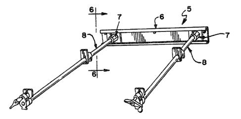
workpieces present;
FIG. 4 is an elevational view of the wall
bracket which forms one component of a kit for forming the
pipe clamp installation shown in FIG. 3;
FIG. 5 is an end elevational view taken along
line 5-5 of FIG. 4;
FIG. 6 is an end elevational view corresponding
in scale to FIGS. 4 and 5 and taken.on line 6-6 of FIG. 3;
FIG. 7 is a top plan view of the pipe end
receiving socket shown in FIG. 6; and
FIG. 8 a front elevational view of the pipe end
receiving socket shown in FIGS. 6 and 7.
In FIG. 3, a pipe clamp installation is
indicated generally at 5 comprising a wall bracket
indicated generally at 6, a pair of pipe end receiving
sockets indicated generally at 7-7 and a pair of pipe
clamps of conventional known commercial type indicated
generally at 8-8.
The wall bracket 6 is foac°med from a strip of
metal or other suitable material so as to have upper and
lower channels 10 and 11, respectively, extending along
its upper and lower edges. The bracket 6 is provided with
a plurality of apertures 12-12 which serve as holes for
screws or nails used to secure the bracket to a wall or
other vertical surface. Two or more pipe end receiving
sockets '7 are provided comprising a square or rectangular
base 13 and a projecting pipe end receiving socket
formation 14. The top and bottom exposed edges of the
base c have such thickness and vertical dimension as to
fit readily and securely in the channels 10 and 11 of the
bracket 5 as shown in FIG. 6. Preferably, the rear side
of the base 6 is partially relieved as indicated at 15 so

-w
-3-
as to provide clearance for the heads of screws or other
fasteners used to mount the wall bracket 6.
The socket formation 14 is preferably flat sided
and provided with a tapped set screw hole 16 to receive a
set screw. The socket formation 14 has a socket hole or
recess 17 (FIG. 8) dimensioned to receive the end 20
(FIG. 6) of a pipe clamp 8. ~y tightening a set screw in
the tapped opening 16, the pipe end 20 may be locked or
fastened into place against accidental removal.
In use, the pipe ends 20 of a pair of the pipe
clamps 8 are inserted into the socket formations 14 on the
socket 7 and then the set screws are firmly tightened.
The sockets 7 are then spread apart, the desired distance
depending upon the job to be accomplished in the
installation 5. In FIG. 1, the clamps 8 are shown
clamping a panel 21 to a workpiece 22. In FIG. 2, the
pipe clamps 8 are shown set up to clamp together four
boards 23 with the assistance of two additional pipe
clamps 24-24.
It will be appreciated that several of the
brackets 6 may be mounted on the same wall, either in a
vertical arrangement or in a side-by-side arrangement. ~y
lengthening the wall bracket 6 and providing a suitable
number of the sockets 7 it will be seen that pipe clamp
installations of various widths may be set up to handle
projects of substantial width.
By having the pipe clamps 8 mounted in
cantilever fashion from a wall bracket 6, the
installation 5 can be utilized to accommodate workpieces
with vertical dimensions which extend both above and below
the level of the pipe clamps 8. Further, if for any
reason it is desired to set up one job and then set it
aside fox another job, it will be seen that it is only
necessary to loosen the set screws in the socket
formations 14 and withdraw the pipe ends from the sockets.

Representative Drawing
A single figure which represents the drawing illustrating the invention.
Administrative Status

For a clearer understanding of the status of the application/patent presented on this page, the site Disclaimer , as well as the definitions for Patent , Administrative Status , Maintenance Fee  and Payment History  should be consulted.

Administrative Status

Title Date
Forecasted Issue Date 2005-11-15
(22) Filed 1994-04-07
(41) Open to Public Inspection 1994-10-29
Examination Requested 2001-04-03
(45) Issued 2005-11-15
Deemed Expired 2011-04-07

Abandonment History

There is no abandonment history.

Payment History

Fee Type Anniversary Year Due Date Amount Paid Paid Date
Application Fee $0.00 1994-04-07
Registration of a document - section 124 $0.00 1994-09-20
Maintenance Fee - Application - New Act 2 1996-04-08 $100.00 1996-04-01
Reinstatement: Failure to Pay Application Maintenance Fees $200.00 1997-04-25
Maintenance Fee - Application - New Act 3 1997-04-07 $100.00 1997-04-25
Maintenance Fee - Application - New Act 4 1998-04-07 $100.00 1998-03-31
Maintenance Fee - Application - New Act 5 1999-04-07 $150.00 1999-03-18
Maintenance Fee - Application - New Act 6 2000-04-07 $150.00 2000-03-20
Maintenance Fee - Application - New Act 7 2001-04-09 $150.00 2001-03-28
Request for Examination $400.00 2001-04-03
Maintenance Fee - Application - New Act 8 2002-04-08 $150.00 2002-03-28
Maintenance Fee - Application - New Act 9 2003-04-07 $150.00 2003-03-26
Maintenance Fee - Application - New Act 10 2004-04-07 $250.00 2004-04-07
Maintenance Fee - Application - New Act 11 2005-04-07 $250.00 2005-03-17
Final Fee $300.00 2005-08-18
Maintenance Fee - Patent - New Act 12 2006-04-07 $250.00 2006-03-09
Maintenance Fee - Patent - New Act 13 2007-04-10 $250.00 2007-03-19
Maintenance Fee - Patent - New Act 14 2008-04-07 $250.00 2008-03-17
Maintenance Fee - Patent - New Act 15 2009-04-07 $450.00 2009-03-18
Owners on Record

Note: Records showing the ownership history in alphabetical order.

Current Owners on Record
ADJUSTABLE CLAMP CO.
Past Owners on Record
SCHNELL, MARK
Past Owners that do not appear in the "Owners on Record" listing will appear in other documentation within the application.
Documents

To view selected files, please enter reCAPTCHA code :


To view images, click a link in the Document Description column. To download the documents, select one or more checkboxes in the first column and then click the "Download Selected in PDF format (Zip Archive)" or the "Download Selected as Single PDF" button.

List of published and non-published patent-specific documents on the CPD .

If you have any difficulty accessing content, you can call the Client Service Centre at 1-866-997-1936 or send them an e-mail at CIPO Client Service Centre.


Document
Description 
Date
(yyyy-mm-dd) 
Number of pages   Size of Image (KB) 
Representative Drawing 1998-08-17 1 17
Cover Page 2005-10-19 1 37
Drawings 1995-04-14 2 75
Description 1995-04-14 3 153
Cover Page 1995-04-14 1 102
Abstract 1995-04-14 1 55
Claims 1995-04-14 2 133
Representative Drawing 2004-06-18 1 10
Claims 2005-01-05 2 77
Assignment 1994-04-07 6 303
Prosecution-Amendment 2001-04-03 1 44
Fees 1997-05-22 1 27
Fees 2004-04-07 1 33
Prosecution-Amendment 2004-07-08 2 34
Prosecution-Amendment 2005-01-05 4 145
Correspondence 2005-08-18 1 33
Fees 1997-04-25 1 50
Fees 1997-04-25 1 45
Fees 1996-04-01 1 50