Note: Descriptions are shown in the official language in which they were submitted.
1264-2
WOODEN I-BEAM ASSEMBLY MACHINE
AND CONTROL SYSTEM THEREFOR
Technical Field
The present invention relates generally to improved
apparatus and methods of making a wooden I-beam from a
pair of wood flanges and web members interconnecting the
flanges and, more particularly, to control systems
allowing for operator control over the various flange and
web drive systems.
Background Art
Fabricated wooden I-beams each comprising a pair of
wooden flanges and web members having longitudinal edges
received in grooves of the flanges are becoming
increasingly popular due to the rising costs of sawn
lumber and the scarcity of good quality wood capable of
producing beams of large size. The fabricated wooden I-
beams require less wood and also reduces the costs of
transportation due to their lower weight. Wooden I-beams
of this type have been disclosed extensively in the prior
art with exemplary patents being U.S. Patent Nos.
3,490,188, 4,074,498, 4,191,000, 4,195,462, 4,249,355,
4,336,678, 4,356,045, 4,413,459, 4,456,497 and 4,458,465.
Prior known procedures for forming fabricated wooden
I-beams by gluing the members together have generally
entailed the use of various conveyor and drive assemblies
in which a series of webs are driven a long a web conveyor
line in either spaced or end-to-end abutting
relationship, with a pair of grooved f langes driven along
,~'".~,
..
opposite sides of the web conveyor. The flanges are
driven with their grooves facing the webs and are
gradually converged toward the conveyed webs so that the,
longitudinal web edges, usually pre-glued, enter the
grooves to form an interconnecting glued joint
therebetween.
In most prior art arrangements of which we are
aware, the flange drive roll assemblies engage the narrow
faces of the flanges which result in poor surface contact
and inadequate or inefficient control over traction
forces .
Another problem with prior art systems of which we
are aware is that the flanges are typically conveyed
through the machine in which flange bottom support is
provided with horizontal rolls. At higher speeds of
operation, these rolls tend to create undesirable
vibration which causes the flanges to bounce. This may
result in mis-alignment with the plane along which the
webs are conveyed.
In most prior art assembly lines of which we are
aware, one of the machine sides is fixed while the other
machine side is laterally movable to provide for lateral
adjustment for different web widths. This type of system
necessitates the use of web drive systems which are
formed with universal spline joints and therefore
necessitate the need for sliding spline drives. This
unnecessarily increases the cost and sophistication of
the machine.
Another significant problem associated with prior
art assembly lines of which we are aware is that the
various web and flange drive systems are extensively
manually adjusted prior to any particular production run
and there exists no control system associated with the
machine to allow for repeatability in performance.
Therefore, there exists difficulty in the ability to
replicate and control the manufacturing process.
;: ::.
.::'
3
It is accordingly one object of the present
invention to control the forces against the webs and
against the flanges with the web and flange drives to
obtain uniform, repeatable and adequate force
applications.
Another object is to control the process to ensure
that the outfeed is running at a substantially constant
velocity while regulating the forces and the speed at
which the webs and flanges are driven and compressed
together.
Another object is to control the web and flange
infeed and outfeed drives with hydraulically operated
motor drives that have closed loop servo controls
utilizing encoders to sense velocity and hydraulic
pressure transducers to sense torque loading.
Still a further object is to utilize simple and easy
to operate adjustment mechanisms to accommodate webs of
different width and thickness and different flange sizes.
Still a further object is to improve traction forces
driving the flanges through the system and to provide for
the smooth flow of flanges with minimum bounce and
vibration.
Disclosure of the Invention
A production line assembly machine for manufacturing
a wooden I-beam from a pair of elongated wooden flange
members and planar wooden web members, in accordance with
the present invention, comprises a pair of flange chutes
mounted to a machine base for conveying an opposing pair
of flanges along left and right hand sides of the
machine, respectively. A flange infeed drive assembly
drives the flanges along the flange chutes. A web
conveyor area is disposed between the flange chutes for
conveying the web members between the left and right
flange pairs. A web drive system drives the webs in end-
to-end relationship between the flange chutes. The
..a
:. ..
....
flange chutes converge towards the machine center line
axis to enable the web edges to be respectively inserted
into the flange grooves in joined relationship to form
the beam. A flange outfeed drive assembly then engages
the flanges of the joined beam to convey the same towards
the discharged end of the machine.
In accordance with the invention, a lateral
adjustment mechanism is connected between the flange
chutes and the machine base for simultaneously moving the
chutes in either inward or outward center justified
relation to the machine center line axis to thereby vary
the spacing between the flanges relative to the center
line and allow for use of webs of different width. The
feature of center line justified lateral adjustment
eliminates the need for complex web drives formed with
universal splined driving axes and also results in a
mechanism which is easy to adjust. Preferably, closed
loop feedback control of this horizontal positioning
control would be provided to assure machine set-up was
accurate and maintained.
In the preferred embodiment, the lateral adjustment
mechanism includes a plurality of laterally extending
lead screw assemblies mounted to the machine base at
longitudinally spaced intervals. Each lead screw
assembly preferably includes a lead screw having an
unthreaded central portion and opposite end portions
which are left and right handed threaded portions,
respectively. Bearing members are attached to the
machine base for rotatably supporting the unthreaded
central portion. A pair of lateral movement transmitting
mechanisms are provided, each including at least one
slide block and nut arrangement both connected with a
respective one flange chute and in respective sliding
engagement with the central portion and an associated one
of the threaded portions. Rotation of the lead screw
causes the chutes to jointly move laterally inward or
5
outward through the action of the left and right handed
screw portions.
The lateral adjustment mechanism preferably also
includes a drive system having a motor and connecting
drive shafts for synchronously rotating each of the lead
screws.
Each flange chutes preferably has a bottom formed
with a generally flat surface extending the length of the
machine to support the flanges in smooth sliding
engagement. This eliminates the need for supporting
bottom rolls that could create undesirable vibration and
bounce at higher operating speeds.
The flange infeed drive assembly preferably includes
a plurality of drive rolls respectively having vertical
rotational axes and located adjacent each chute to engage
the wide faces of the flanges. Plural idler rolls are
respectively associated with each drive roll and are
positioned on opposite sides of the associated chute to
contact the opposite wide face of the flange being
conveyed along the chute. By contacting the wider faces
of the flanges, greater traction forces are generated to
ensure positive and firm control over the flanges during
conveyance.
Each idler roll preferably has an axis of rotation
which is canted toward the chute by a predetermined angle
from the vertical. In the preferred embodiment, this
predetermined angle is approximately one-half to one
degree and eliminates the need for plural overboard hold
down rolls in each chute.
The infeed flange drive rolls are preferably
swingably mounted to associated chutes on a swing arm
pivotally connected to the chute. A cylinder extending
between the chute and the drive roll is used to move the
drive roll between a flange engaging position and a dis-
engaging position. This cylinder also controls pinching
forces.
.-.,
The web conveyor area includes a pair of web bottom
support rails located between the chutes. In accordance
with another feature of this invention, plural vertical
column screws are used to connect the rails to the
machine base. Rotation of the column screws results in
vertical height adjusting movement of the rails relative
to, and inbetween, the chutes.
A plurality of nut portions extend between the
rails. The column screws are respectively threadedly
received in the nut portions. A first upper bearing
mounted between the rails is used to rotatably connect
the upper portion of the screw to the machine base. A
second lower bearing rotatably connects the lower portion
of the screw to the base. This arrangement allows for
fine and synchronous control over the rail vertical
height adjustment process while enabling lateral forces
generated during the assembly process to be transmitted
to the machine base from the web train through the column
screws.
Optionally, a single motor is interconnected to each
column screw through plural drive shafts so as to provide
for synchronous screw rotation. Preferably, closed loop
feedback control of this vertical positioning control
would be provided to assure machine set-up was accurate
and maintained.
In accordance with another preferred feature of the
this invention, the infeed flange drive rolls, the web
drive rolls (top and bottom) and the flange outfeed drive
rolls are all provided with a dedicated hydraulic motor..
These drive motors are connected in predetermined
hydraulic circuits which are operated through
microprocessor control to control the speed and forces
exerted by the different drive rolls against the flanges
and the webs to ensure a substantially constant product
speed through the machine. Preferably, closed loop
feedback control of all web and flange drives would be
CA 02120846 2005-09-23
7
used to coordinate the relationship between infeed flange
drives, web feed drives, and the outfeed drives. Feedback of
drive positions and drive forces control the point of closure of
the web and web-to-flange joints and the compression forces
applied to these joints.
The control means is further operable to adjust the left
and right outfeed drive rolls based upon means for sensing an
identifier (e. g., a notch) in each flange to ensure matched left
and right outfeed drive speeds, to eliminate creep of either the
left or right hand flange.
According to a first broad aspect of an embodiment of the
present invention, there is disclosed a production line assembly
machine for manufacturing a wooden I-beam from a pair of
elongated wooden flange members each having a longitudinal
groove formed in one of the faces of the flange members, and
planar wooden web members having opposite longitudinal edges is
comprised of:
(a) a pair of flange chutes mounted to a machine base for
conveying an opposing pair of flange members along left and
right hand sides of the machine, respectively;
(b) a flange infeed drive assembly for driving said pair of
flange members along said flange chutes;
(c) a web conveyor area between the flange chutes for
conveying said web members between said left and right hand
flanges;
(d) a web drive system for driving said web members in end-
to-end relationship between said flange chutes, said flange
chutes converging towards the machine center line axis to enable
the edges of the web members to be respectively inserted into
the converging flange grooves in joined relationship to form the
beam;
CA 02120846 2005-09-23
7a
(e) a flange outfeed drive assembly engaging the flange
members of the joined beam to convey same towards the discharge
end of the machine; and
(f) a lateral adjustment mechanism connected between the
flange chutes and machine base for simultaneously moving the
flange chutes in center justified relation to the machine center
line axis; wherein the flange chutes are moved so that the
center justified relation to the machine center line axis is
chosen from the group consisting of an inward center justified
relation to the machine center line axis and an outward center
justified relation to the machine center line axis to thereby
vary the spacing between the flange members and allow for use of
web members of different width.
According to a second broad aspect of an embodiment of the
present invention, there is disclosed a production line assembly
machine for manufacturing a wooden I-beam from a pair of
elongated wooden flange members each having a longitudinal
groove formed in one of the faces of the flange member, and
planar wooden web members having opposite longitudinal edges,
comprising:
(a) a pair of flange chutes mounted to a machine base for
conveying an opposing pair of flanges along left and right hand
sides of the machine, respectively;
(b) a flange infeed drive assembly for driving said pair of
flanges along said flange chutes;
(c) a web conveyor area between the flange chutes for
conveying said web members between said left and right hand
flanges;
(d) a web drive system for driving said web members in end-
to-end relationship between said flange chutes, said flange
chutes converging towards the machine center line axis to enable
the edges of the web members to be respectively inserted into
CA 02120846 2005-09-23
7b
the converging flange grooves in joined relationship to form the
beam;
(e) a flange outfeed drive assembly engaging the flange
members of the joined beam to convey same towards the discharge
end of the machine;
whereby each flange chute has a bottom formed with a
substantially flat surface extending the length of the machine
to support the flanges in smooth sliding engagement, and
wherein said chute bottom extends continuously the length
of the machine.
According to a third broad aspect of an embodiment of
the present invention, there is disclosed a production line
assembly machine for manufacturing a wooden I-beam from a pair
of elongated wooden flange members each having a longitudinal
groove formed in one of the faces of the flange member, and
planar wooden web members having opposite longitudinal edges,
comprising:
(a) a pair of flange chutes mounted to a machine base for
conveying an opposing pair of flange members along left and
right hand sides of the machine, respectively;
(b) a flange infeed drive assembly for driving said pair of
flange members along said flange chutes, wherein said flange
infeed drive assembly includes a plurality of drive rolls
respectively having vertical rotational axes and located
adjacent each chute to engage the wide faces of said left and
right flange members;
(c) a web conveyor area between the flange chutes for
conveying said web members between said left and right hand
flange members;
(d) a web drive system for driving said webs in end-to-end
relationship between said flange chutes, said flange chutes
converging towards the machine center line axis to enable the
CA 02120846 2005-09-23
7C
edges of the web members to be respectively inserted into the
converging flange grooves in joined relationship to form the
beam;
(e) a flange outfeed drive assembly engaging the flange
members of the joined beam to convey same towards the discharge
end of the machine.
According to a fourth broad aspect of an embodiment of the
present invention, there is disclosed a production line assembly
machine for manufacturing a wooden I-beam from a pair of
elongated wooden flange members each having a longitudinal
groove formed in one of the faces of the flange member, and
planar wooden web members having opposite longitudinal edges,
comprising:
(a) a pair of flange chutes mounted to a machine base for
conveying an opposing pair of flange members along left and
right hand sides of the machine, respectively;
(b) a flange infeed drive assembly for driving said pair of
flange members along said flange chutes;
(c) a web conveyor area between the flange chutes for
conveying said web members between said left and right hand
flange members, wherein said web conveyor area includes a pair
of web bottom support rails located between said chutes, and
further including a plurality of vertical column screws
connecting said rails to said machine base, whereby rotation of
said column screws results in vertical height adjusting movement
of said rails relative to, and inbetween, said chutes;
(d) a web drive system for driving said web members in end-
to-end relationship between said flange chutes, said flange
chutes converging towards the machine center line axis to enable
the web edges to be respectively inserted into the converging
flange grooves in joined relationship to form the beam;
CA 02120846 2005-09-23
7d
(e) a flange outfeed drive assembly engaging the flange members
of the joined beam to convey same towards the discharge end of
the machine.
According to a fifth broad aspect of an embodiment of the
present invention, there is disclosed a production line assembly
machine for manufacturing a wooden I-beam from a pair of
elongated wooden flange members each having a longitudinal
groove formed in one of the faces of the flange member, and
planar wooden web members having opposite longitudinal edges,
comprising:
(a) a pair of flange chutes mounted to a machine base for
conveying an opposing pair of flanges along left and right hand
sides of the machine, respectively;
(b) a flange infeed drive assembly for driving said pair of
flanges along said flange chutes;
(c) a web conveyor area between the flange chutes for
conveying said web members between said left and right hand
flanges;
(d) a web drive system for driving said web members in end-
to-end relationship between said flange chutes, said flange
chutes converging towards the machine center line axis to enable
the edges of the web members to be respectively inserted into
the converging flange grooves in joined relationship to form the
beam;
(e) a flange outfeed drive assembly engaging the flange
members of the joined beam to convey same towards the discharge
end of the machine;
wherein said flange infeed drive assembly includes a
plurality of infeed drive rolls each driven by a dedicated
hydraulic motor mounted thereto,
CA 02120846 2005-09-23
7e
wherein said web drive system includes a plurality of web drive
rolls each driven by a dedicated hydraulic motor mounted
thereto,
wherein said web drive rolls include top web drive rolls
and bottom web drive rolls,
wherein said flange outfeed drive assembly includes a plurality
of outfeed drive rolls respectively engaging each of the left
and right flanges of the formed beam, each outfeed drive roll
being driven with a dedicated hydraulic motor mounted thereto,
further comprising control means for driving said outfeed drive
rolls at a preselected, substantially constant speed, said
control means being operable to control each said infeed flange
drive roll and said web drive rolls to ensure that said outfeed
drive rolls are maintained at said constant speed.
In accordance with a sixth broad aspect of an embodiment of
the present invention, there is disclosed a method of
manufacturing a wooden I-beam from a pair of elongated wooden
flange members each having a longitudinal groove formed in one
of the faces of the flange member, and planar wooden web members
having opposite longitudinal edges, comprising the steps of
conveying an opposing pair of said wooden flange members along
left and right hand flange chutes within a machine utilizing a
plurality of infeed flange drive rolls; conveying a plurality of
web members between said flange chutes in end-to-end
relationship with a plurality of top and bottom web drive rolls;
said left and right hand wooden flange members being gradually
converged to enable the edges of the wooden web members to be
respectively inserted into the flange grooves in joined
relationship to form the beam; conveying the joined beam towards
a discharge end of said machine with a plurality of flange
outfeed drive rolls, and controlling the speed of operation of
said flange infeed drive rolls and said web drive
CA 02120846 2005-09-23
7f
rolls so that a substantially constant output speed is achieved
with said flange outfeed drive rolls.
Brief Description of Drawings
Figure 1 is a schematic plan view of an overall production
line assembly for manufacturing wooden I-beams;
Figure 2A is an elevational view of a wooden I-beam
assembly machine to which the present invention is directed;
Figure 2B is a top plan view of the wooden I-beam assembly
machine of Figure 2A;
Figure 3 is an enlarged plan view of a flange infeed
section of the assembly machine;
Figure 4 is a detailed bottom plan view of a portion
of the infeed section to depict infeed vertical flange
drive rolls;
Figure 5 is a partial elevational sectional view of
an infeed flange drive assembly of Figure 4;
Figure 6 is a further sectional view of an infeed
vertical flange drive roll assembly;
Figure 7 is an enlarged, partly schematic and partly
sectional view similar to Figure 5;
Figure 8A is a sectional elevational view taken
along the line 8A-8A of Figure 2B to depict a lateral
adjustment mechanism according to the invention;
Figure 8B is an enlarged detailed view of a lead
screw of the lateral adjustment mechanism depicted in
Figure 8A;
Figure 9 is a sectional view, partly schematic, of
a flange groove cutter and inside edge Baser assembly in
the infeed section of the machine;
Figure '10 is an elevational sectional view of an
outside flange edge Baser assembly in the infeed section;
Figure 11A is a top plan view of the machine base
depicting the placement of the lead screw assemblies for
providing center justified lateral adjustment;
Figure 11B is an elevational view of the lead screw
assemblies of Figure 11A;
Figure 12 is a sectional view taken along the line
12-12 of Figure 11A;
Figure 13 is a sectional elevational view taken
through the line 13-13 of Figure 2B depicting only the
relative location of the left and right flange chutes and
the web bottom support rails;
Figure 14 is a view similar to Figure 13 taken
through a web feeder gate area;
Figure 15 is an exploded elevational view of a
series of column lead screw assemblies for providing
vertical or height adjustment of the web support rails;
f.r ~, ~a ~ E.~ ~
.~
... g
Figure 16 is a top plan view of the web bottom
support rails of Figure 15 as well as the web bottom run-
up and traction rolls and lugged web chain teed assembly
carried on said support rails;
Figure 17 is an elevational view, partly in
schematic form, depicting a matched pair of top and
bottom web run-up or traction rolls in the web drive
assembly of the invention;
Figure 18 is a side elevational view of a matched
pair of web top and bottom traction or run-up rolls as
depicted in Figure 17;
Figure 19 is an enlarged top plan view of an outfeed
section of the machine;
Figure 20 is an end elevational view, partly in
section, of a pair of flange outfeed vertical drive rolls
in accordance with the invention;
Figure 21 is a top plan view of the matched outfeed
drive roll assemblies of Figure 20;
Figures 22 and 23 are top and side views,
respectively corresponding to Figures 2B and 2A,
depicting the various hydraulic drive motors and pinching
cylinders used in the various drive assemblies of the
present invention;
Figure 24 is a hydraulic diagram depicting the eight
microprocessor controlled axes in the present invention;
Figure 24A is a hydraulic diagram of the pinching
cylinders associated with the various drives;
Figure 25 is a hydraulic diagram depicting the
manner in which the f lange infeed pinch cylinders are
interconnected;
Figure 2.5 is a hydraulic diagram depicting the
hydraulic connection between the flange outfeed pinch
cylinders;
Figure 27 is a hydraulic diagram depicting the
manner of connection of the web feed pinch cylinders;
~~ z
Figure 28 is a hydraulic diagram of the manner of
connection between the flange infeed and outfeed left and
right hand drives;
Figure 29 is a hydraulic diagram depicting the
5 manner of connection between the machine lateral
adjustment drive, web bottom feed lug drive and web feed
height adjustment drive axes;
Figure 30 is a hydraulic diagram depicting the
manner of hydraulic connection between the web speed-up
10 drive and the web compression drive;
Figures 31A and 31B are top and elevational
sectional views corresponding to Figures 2B and 2A to
depict the location of various photo-detectors used to
provide input signals into the microprocessor based
control system;
Figure 32 is a block diagram depicting the basic
operator sequence to load and run the I-beam assembly
machine;
Figure 33 is a hydraulic diagram which better
depicts the interface between the multiple axis
controller modules with the lead screw assemblies for
adjusting machine width;
Figure 34 is a block diagram depicting the typical
closed loop servo control used for controlling infeed and
outfeed flange drive axes #1-9; and
Figure 35 is a block diagram illustration depicting
the controller interface with the web lug feeder, and web
speed-up and compression drive rolls.
Best Mode for CarrLring out the Invention
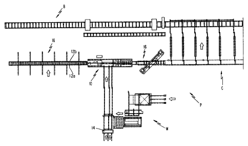
Figure 1 is an illustration of an overall production
area P utilizing an assembly line 10 which is the subject
of the present invention for making wooden I-beams 12
( see Figure 20 ) having wood flanges or chords 12a and 12b
("flange(s)" and "chord(s)" are used interchangeably
throughout this specification) and wooden web members 14,
,:,.....
11
The assembly line or machine 10 performs different
operations to secure the identical flanges 12a,12b to the
series of webs 14 to form web-to-chord joints. Each web
14 is preferably formed of plywood or oriented strand
board ("OSB" which is a form of flake board wherein
strains of wood are oriented, overlapped and secured
together by suitable glues to achieve strength properties
superior to plywood) or the like. The webs 14 may be of
varying thickness and, in the assembled wooden I-beam,
form a plurality of abutted sheets of such boards. The
sheets 14 are rectangular having a long dimension along
a longitudinal axis which is substantially parallel to
the longitudinal axes of the elongated flanges 12a,12b.
The webs 14 form butt joints with one another preferably
secured together with adhesive or glue.
Each flange 12a,12b has a generally rectangular or
square cross-section perpendicular to its longitudinal
axis. The flanges 12a,12b may be formed of commercially
available wooden structural boards or may be formed of
laminated veneer lumber ("LVL") which is readily
available in a large variety of lengths and thicknesses.
The flanges are cut from rectangular stock material and
provided with grooves either off the assembly line 10 at
a flange forming area in a known manner, or within the
assembly line as described, infra. After forming off the
assembly line, the grooved flanges (or ungrooved flanges
as described infra) are discharged onto an outfeed table
for transfer to a flang$ feed location via a lateral
conveyor ramp. The flanges are respectively grouped on
opposite sides of a roll casel6 for feeding into the
assembly machine 10 along opposite left and right hand
sides thereof .
The individual web members 14 are pre-cut to desired
length and width and undergo a beveling operation whereby
their upper and lower longitudinal edges are beveled or
tapered to respectively interfit with the flange groove
CA 02120846 2004-08-23
12
as described below. The grooves preferably have the same
cross-section as the web beveled edges or may have other
cross-sections as known in the art. The web forming
steps may occur off-line, as known in the art, in a web
forming area generally designated by reference letter W.
In that area, the web-to-web joints are also profiled.
The formed webs 14 are conveyed to the assembly machine
for positioning as a stack within a web hopper located
downstream from the flange infeed location.
10 The flanges 12a,12b are conveyed respectively along
the opposite sides of the webs 14 which is formed as a
continuous web in the assembly line 10. The flanges
12a,12b are gradually converged (in the area downstream
f rom section lines 13 - 13 in Figure 2B ) towards the
continuous web 14 so that the beveled edges enter the
grooves to form press-fitted interconnecting joints
therebetween and thereby the wooden I-beam. The beveled
edges and grooves are preferably glued prior to joining.
The wooden I-beam may optionally be passed through a
radio frequency tunnel as is well known which cures the
glued joints of the I-beam. The I-beam is discharged
onto a outfeed table provided with a f lying cutof f saw 16
cutting the beam to desired length. The cut beams are
transferred laterally from the outfeed table by means of
a cross-transfer conveyor C which provides a minimum cure
dwell time before the beams are ultimately stacked and
bundled at station B for subsequent shipment.
As mentioned above, the present invention is
directed to the assembly line or machine 10 which
contains a number of unique features providing for
positive control over the flanges throughout the machine
and which also allows the machine to be easily adjusted
to accommodate different flange sizes and web widths and
lengths in an accurate, quick and easy to set up manner
on the production floor P. The I-beam assembly machine
10 of the present invention also features a control
......
... .,
13
system in which the various web, flange, and beam power
drives are interlocked through speed and pressure control
loops which will enable the machine operator to
manufacture wooden I-beams in which the flanges 12a,12b
and webs 14 are joined together at controllable and
settable speeds and forces to ensure uniform, reliable
product integrity.
Assembly machine 10 of the present invention is
comprised of three sections (see Figure 2B); a flange
infeed section 20 at the upstream end thereof; a web
hopper feed area 22 in the center section thereof; and a
beam outfeed section 24 at the downstream end thereof.
The three sections 20-24 are all supported on a fixed,
common machine frame 26 extending the entire length of
the machine. A unique system of adjustable drive screw
assemblies 28 (see Figures SA,BB and 11A,11B) mounted to
the frame at 26 longitudinally spaced intervals along the
entire length of machine 10 are used to achieve center
line justified adjustment of the flange and beam drive
sets and supports throughout the machine, as discussed in
detail below, to control set-up spacing between the
flanges 12a,12b and allow for manufacture of wooden I-
beams of varying height. The web tap and bottom drive
sets and web supports in the web center section 22 only,
is vertically adjustable utilizing a unique series of
column screws 30 (Figures 15 and 16 ) to easily ad just for
webs of different thicknesses.
The fixed machine frame 26 which defines the support
base of the machine 10 is comprised of a pair of parallel
side frames 32a and 32b extending horizontally the full
length of the machine along lef t and right hand sides
thereof, respectively. These side frames 32a,32b are
connected together at longitudinally spaced intervals
with laterally extending horizontal braces or cross ties
34 which may be welded or bolted at opposite ends thereof
to the frames. The resulting main frame assembly 26 is
14
supported above a production floor space with vertical
posts 36.
Flanae Infeed Section
With reference now to Figure 3, the flange infeed
section 20 is comprised of a pair of left and right
horizontally extending infeed plates 38a and 38b which
are adapted to support the flanges 12a,12b entering the
machine from roll case 16 as well as the flange infeed
drive roll assemblies 40 discussed, infra. As best
14 depicted in Figure 8A, the left and right infeed plates
38a,38b are movably mounted to the support base 26 for
lateral adjustment through a pair of the adjustable lead
screw drive assemblies 28 located at opposite ends of the
infeed section.
With references to Figure 8A and 8B, each drive
screw assembly 28 includes a lead screw 41, which
comprises a smooth or unthreaded center section rotatably
supported on a cross tie 34 through a series of pillow
block bearings 44 respectively fixed to the upper end of
a support bar 46 projecting upwardly from the cross tie.
The three pillow block bearings 44 rotatably support the
smooth center section 42 of the lead screw 41 at opposite
ends and the center section thereof. A right handed
threaded portion 48a and a left handed threaded portion
48b are respectively formed outwardly adjacent the smooth
center section 42. The outermost end 50 of each right
and left threaded section 48a.48b is unthreac~P~i ant
rotatably received within additional pillow block
bearings 52 mounted to the left and right side frames
32a,32b. The outermost reduced diameter end 54
projecting from the unthreaded journal portion 50 of the
right hand thread 48a constitutes a driven screw portion
which is adapted to rotate each of th a four lead screws
in a common clockwise or clockwise direction throughout
the machine in a synchronous manner, as discussed more
.;>a 15
fully below, to adjust the lateral spacing between
flanges 12a,12b and therefore beam height.
Still with reference to Figure 8A, the inboard or
innermost lengthwise edge of each infeed plate 38a,38b
supports a bushed block 56 which is slidably mounted on
the smooth center section 42 of each lead screw 41 for
smooth lateral sliding movement therealong. A lead screw
nut 58 pro jects downwardly from the outboard or outermost
lengthwise edge of each support plate 38a,38b for
threaded engagement with the right and left threaded
portions 48a,48b of the lead screws, respectively, to
transmit lateral motion to each plate caused by the
turning lead screws.
The above-described lead screw assemblies 28, each
formed with right and left hand thread segments 48a,48b
at opposite end portions thereof, extend in the lateral
or width direction of the machine 10 and essentially
provide the sole means of supporting the left and right
infeed plates 38a,38b on the machine frame 26 as well as
the corresponding left and right outfeed plates 220a,220b
in the outfeed section 24 as will be discussed more fully
below.
With reference to Figures 11A, 11B and 12, the
driven end portion 54 of each of the four lead screws 41
is connected through a coupling 60 to a right angle gear
box 62 mounted to the left hand machine side frame 32a
with a bracket 64. The gear boxes 62 respectively
associated with each of the lead screws 41 are
interconnected to each other through a series of drive
shafts 64 and supporting pillow block bearings 66 to
transmit rotative output from a hydraulic motor 68
mounted to one of the gear boxes 62. An encoder 70
(Figure 12) is mounted to the opposite end of the lead
screw 41 directly driven by the motor. This arrangement
advantageously allows fox controlled, synchronous lateral
center justified adjustment of the machine 10.
~~~~~~a~3
'16
In the infeed section 20, the left and right infeed
plates 38a, 38b solely support the flanges 12a, 12b and the
flange drive roll assemblies 40. The upper, inboard
lengthwise edge surface of each infeed plate is machined
with a step adapted to receive a bed plate insert 72 of
hard cold-rolled steel strip which extends the full
length of the infeed section 20 to respectively define a
smooth slide surface supporting a narrow face of each
flange 12a,12b entering the machine 10 from flange feeder
16 along a flange chute 45 having an entrance defined by
a pair of converging angles 74a and.vertical plates 74b
located at the upstream end of the infeed section.' As
best depicted in Figure 6, the vertically extending wide
faces of each flange are adapted to be contacted by an
outer idler roll 76 and an inner flange drive roll 78,
each mounted to an associated one of the infeed plates
38a,38b for rotation about vertical axes 80.
Controlled rotation of the lead screw assemblies 28
in either the clockwise or counter-clockwise direction
results in simultaneous inward or outward lateral
movement of each infeed plate 38a,38b in relation to the
central longitudinal axis L of the machine 10. This
enables the spacing between the flange guide paths
defined by the bed plate insert strips 72 and the paired
sets of vertical flange idler and drive rolls 76,78 to
allow for manufacture of wooden I-beams nominally of 9
inches wide to about 24 inches wide. The feature of
providing for center line adjustment in the unique manner
set forth hereinabove advantageously eliminates the need
for drive systems and width adjustment systems which
require universal spline joints and sliding spline drives
as known in the prior art. Another advantage of center
line adjustment is the ability to utilize a single web
hopper drive that may be laterally immovably mounted
along the machine center line L to eliminate the need for
a web drive system that is laterally openable with
~~ s ~; ~"i o ~'
~.1.~.~~r'~(~~i
''1
17
universal joints. The web hopper feeder herein, as will
be seen below, is center line registered without the need.
for web feeding mechanisms which are adjustable in the.
width or lateral direction.
With reference to Figure 3, there are four flange
drive assemblies 40 mounted exclusively to each of the
left and right infeed plates 38a,38b at longitudinally
spaced locations to drive the individual flanges 12a,12b
along the infeed section 20 into the web hopper center
section 22. Figures 4-7 are illustrations of one of the
identical flange drive assemblies 40 defining each flange
chute 45. With reference to Figure 6, each flange drive
roll assembly 40 is comprised of idler roll 76 having
vertical axis of rotation 80 and which is mounted to the
top surface of each infeed plate 38a,38b through a pair
of roller bearings 82 encircling a hub 84 bolted to the
plate outwardly adjacent the bed plate insert 72 defining
the flange slide path of each chute 45.
The associated flange drive roll 78 is swingably
mounted to the associated infeed plate 38a,38b so as to
be inwardly ad jacent the inboard longitudinal edge of the
corresponding flange slide path. As best depicted in
Figures 4-7, each flange drive roll 78 has a vertical
axis of rotation 80' defined by a tapered output shaft 86
25' of a hydraulic motor 88 mounted to one end of a pivot or
swing arm 90 extending parallel to and below the
associated infeed plate 38a,38b. As best depicted in
Figures 4 and 7, the opposite end of each swing arm 90 is
pivotally connected to the associated infeed plate
38a,38b by means of upper and lower piloted flange
bearings 92 respectively received in cylindrical recesses
94 formed in top and bottom surfaces of the infeed plate
and bolted to the pivot arm through a pin and nut
arrangement 96. A hydraulic cylinder 98 having a
cylinder end 98a pivotally mounted to the lower surface
of the associated infeed plate 38a,38b with a bracket
N 5k. ~~~ )~~
.''1
18
100has a piston rod 102 pivotally connected to the swing
arm 90, through a clevis and pin arrangement 104 (Figure
4), adjacent to the hydraulic motor 88. Hydraulic
actuation of these pinch cylinders 98 operates to pivot
the associated inner vertical flange drive rolls 78 into
and out of contact with the inner wide face of the flange
12a,12b traveling on the slide path.
The feature of driving the flanges 12a,12b through
the machine with vertical flange drive roll assemblies 40
advantageously results in greater surface contact between
the roll surfaces and the wider faces of the flanges, as
opposed to prior art horizontally arranged rolls engaging
the narrower flange faces with less traction. The use of
hydraulic motors 88 with tapered shafts B6 minimizes the
need for precise clearances since each drive roll 78 can
be securely tightened to the tapered shaft simply by
tightening the nut 78a. Of course, straight shafts and
other suitable means may be used in place of tapered
shafts.
As depicted in Figure 3, a series of angles 106
bolted to the top surface of each infeed plate 38a,38b
between adjacent idler rolls 76 assist in defining the
outer extent of each flange chute 45 extending through
the infeed section 20. The opposite, inner lengthwise
extent of each flange chute 45 is defined by the vertical
drive rolls 78 and additional vertical plates 108 mounted
to the inner lengthwise edge of the infeed plate between
the drive rolls. This technique of defining the flange
chutes 45 with inner vertical plates 108 and outer angles
106 is common throughout the machine 1C as will be
apparent from Figure 2B.
In accordance with a further feature of the
invention, the idler rollers 76 are preferably rotatable
about axis 80 which is tilted or canted downwardly in the
direction of conveyance at approximately one-half to one
degree from a vertical plane which extends in the width
~:~'~~~e
..-_.
19
or lateral direction of the machine while maintaining
full face contact with the flange vertical faces. As a
result of extensive experimentation, it has been
discovered that the resulting tilted roll surface 80a of
each idler roll 76 functions to hold the flange members
12a,12b down against the bed plate 72 which eliminates
the need for top rollers or hold-down members exerting a
hold--down force against the narrower top faces of the
flanges. This simplifies machine design and
manufacturing cost.
The infeed section 20 also features a pair of flange
groove cutters 110 (Figures 2A, 2B, 3 and 9) which are
respectively mounted to the left and right infeed plates
38a,38b to form a longitudinal groove in each inward
facing, vertical wide flange face as the flanges 12a,12b
are conveyed towards the downstream end of the infeed
section. As best depicted in Figure 9, each cutter 110
has a cutter motor 112 mounted to a motor mount 114
secured to the top surface of the associated infeed plate
38a,38b through an adjustment screw mechanism 116
permitting lateral adjustment of the cutter head 117
projecting downwardly from the cutter motor. A second
adjustment screw mechanism 118 allows for vertical
adjustment of the cutter head 117 along a slide 120. The
weight of each cutter motor 112 may be supported on the
infeed plate 38a,38b with a smooth slide shaft 122 which
is mounted to extend laterally above and supported on an
associated machine frame cross tie 34 as depicted in
Figure 9. A slide block 124 secured to project below the
associated infeed plate 38a,38b is received on the slide
shaft 122 to support the weight of the cutter assembly
110. In this manner,- the cutter heads 117 are
automatically movable via the slide shafts 122 with the
associated infeed plate 38a,38b during beam height
adjustment while being capable of independent vertical
and lateral adjustment as discussed above. Cutter motor
Y,".~..
112 also supports a pair of edge Baser tools for inside
edge easing.
Figure 10 is an illustration of a cutter edge Baser
130 having an edge Baser motor 132 mounted to and below
5 an associated one of the infeed plates 38a, 38b downstream
from the associated groove cutter 110 (see Figure 3)
through an infeed plate slide 134 and an edge Baser slide
arrangement 136 which allows for lateral adjustment
(through an adjustment screw 134a) and vertical
10 adjustment (through an adjustment screw 136x), both
relative to the infeed plate, of the cutter edge Baser
head 138 projecting upwardly from the infeed plate into
contact with the outer wide flange face.
Web Hopper Feed Area (Machine Center Sectionl
15 Figure 13 is a sectional view illustration of the
left and right flange chutes 45 within the web hopper
infeed or center section 22 of the machine 10. Therein,
each chute bottom is defined by a left and right slide
bar 140a and 140b, each respectively hawing upstream ends
20 which are bolted at 141 to the downstream ends of the
infeed plates 38a,38b and particularly to downstream
projecting stepped end portions of each infeed plate as
best depicted in Figure 3, and downstream ends bolted to
upstream ends 222 of the outfeed plates as discussed more
fully below. The slide bars 140a,140b perform the same
function as the bed plate inserts 72 in the machine
infeed section 20 and thereby define a continuous slide
surface with the inserts to provide smooth, uninterrupted
support for the flanges 12a,12b without utilizing bottom
rollers within the flange chutes 45. Such rollers, as
known in the art, tend to subject the flanges to
undesirable vibration and bounce, unlike the smooth slide
surfaces provided within the flange chutes 45 of the
present invention.
'21
As mentioned hereinabove, angles 106 bolted to the
top surface of the slide bars 140a,140b define the
outermost extent of each flange chute 45 while vertical
plates 108 secured to the inward facing longitudinal edge
of each slide bar define the inwardmost extent of each
chute. Therefore, the flanges 12a,12b being driven
through the infeed section 20 via the flange infeed drive
roll assemblies 40 slide smoothly through their
respective chute 45 defined between these members 106,108
and 140a or 140b without bouncing or vibration.
The vertical plates 108 defining the inwardmost
extent of each flange chute 45 also serves to define the
web side engaging plates within the center section 22.
By virtue of their attachment to the slide bars
140a,140b, these plates 108 are obviously laterally
adjustable through the unique lead screw assemblies 28
described hereinabove to accommodate beam height
adjustments occurring as a result of using different web
widths.
The webs 14 are supported for movement within the
center section 22 through a pair of bottom slide rails
142a and 142b which extend longitudinally between the web
side engaging plates 108. These rails 142a,142b present
smooth upper edges 144 defining a horizontal web support
ramp supporting the webs in smooth sliding engagement.
Figure 14 is an illustration of a web hopper feeder
gate 145 against which a stack of webs 14 are maintained
within the web hopper to allow for controlled sequential
feeding of a bottommost web 14' in the stack utilizing a
lugged web feeder chain assembly 150 (I~'igures 15 and 16)
mounted to and between the support ra i 1 s 14 2a , 14 2b in the
manner described below. The feeder gate 145 is comprised
of a pair of identical feeder sides 152 respectively
mounted to the inward facing vertical surface of the web
hopper side plates 108. These feeder sides 152 are
formed with an upstream facing surface 154 (Figure 15)
~. ~.~ ~ iy L~ ~~
?' 2 2
against which the leading edges of the webs 14 in the
stack are positioned until they descend to the bottommost
stack position below the bottom surface 156 of each side.
Since the web bottom supporting rails 142a,142b are
vertically adjustable in the unique manner described
below, relative to the non-vertically adjustable flange
chutes 45, each feeder side 152 supports a vertical
ad justment screw 158 having a lower end 160 which can
project down from the bottom surface 156 of each feeder
side. Thus, when the web bottom support rails 142a,142b
are adjusted to a lower position, the adjustment screws
158 are correspondingly wmanually (or automatically)
adjusted so that the vertical height of the gate 145
defined between the screw bottoms 160 and the upper web
support edges 144 of the rails is slightly greater than
the thickness of one web 14 but less than twice the web
thickness to ensure singular web feeding in a controlled
manner.
Figures 15 and 16 are illustrations of the web
bottom support rail arrangement which is also used to
support a web bottom run-up roll 162 and a pair of
longitudinally spaced web bottom traction rolls 164
mounted downstream from the run-up roll. As best
depicted in Figure 16, each of the run-up and traction
rolls 162,164 is driven through a hydraulic motor 166
bolted to the left hand web bottom support rail 142a.
The web feeder gate 145 is located upstream from run-up
roll 162 and the lugged web feed chain assembly 150 is
disposed between the support rails 142a,142b upstream
from the gate 145 as described more fully below.
From the foregoing, it can be seen that the web
bottom support rails 142a,142b also support the web run-
up and traction rolls 162,164 as well as the lugged web
feed chain assembly 150 which must be capable of vertical
but not lateral adjustment to accommodate different
flange sizes. To that end, in accordance with a further
.:.: .. 2 3
unique feature of the inventions three vertical column
lead screws 170 are located at opposite ends and at the
center section of the support rails 142a,142b. As best
depicted in Figure 15, the upper end of each column screw
assembly 170 is received within a flanged top bearing 172
rotatably mounted in a stationary upright support 174
attached to one of the machine frame cross ties 34. The
intermediate threaded portion of the column screw 170
threadedly engages a screw nut 176 which is secured to
and extends between the web bottom support rails
142a,142b. The lower end of each column screw 170 is
received in a flanged bottom bearing 178, identical to
the top bearing 172, which is in turn coupled to an
output shaft 179 of a right angle gear box 180. The
right angle gear boxes 180 associated with each column
screw adjustment assembly 170 are interconnected to each
other with drive shafts 182 and connecting support hub
assemblies 184, all driven through a single hydraulic
motor 186.
The unique column screw assemblies 170 of the
invention essentially perform two functions. One
function is to provide for controlled vertical or
elevational adjustment of the web bottom support rails
142a,142b and the web run-up and traction rolls 162,164
as well as the lugged web feed chain system 150 supported
thereon. A second function is to provide an effective
means for transference of the tremendous lateral forces
generated, when the webs 14 mate with the flanges
12a,12b, from the web bottom support rail system
142a,142b to the stationary machine base frame 26 . These
latsral forces are actually backup forces having a force
vector component extending in the upstream direction
opposite the downstream direction of web conveyance.
These forces are transmitted as radial thrust loads from
the column screws through their top and bottom flange
bearings 172,178 and the screw nut 176.
2~ ~~ 3~~~~
::
24
In accordance with a further feature of the
invention, each column screw 170 is preferably about two
inches in diameter and provided with six threads per
inch. This will allow the web bottom slide rails
142a,142b to be accurately vertically positioned
(preferably with a digital readout) while allowing the
threads to absorb a large backup force load since the
column screws have a diameter which is about five times
the diameter of a screw which this thread pitch is
normally associated with.
The lugged web feed chain assembly 150 is mounted to
and between the web bottom support rails 142a,142b, as
best depicted in Figures 15 and 16, upstream from the web
feeder gate 145 and between the center and upstream
column screws 170. The lugged chain assembly 150 is
essentially comprised of a head sprocket 180 rotatable
about a laterally directed, horizontal axis 182 and
directly connected to a hydraulic motor lB4a mounted to
the left hand web bottom support rail 142a. The upstream
end of the chain feed assembly 150 is defined by a
smaller diameter tail sprocket 186 mounted to and between
the web bottom support rails 142a,142b. A lugged chmin
assembly 188 is trained around both the head drive and
tail sprockets 180,186 and carries a pair of lugs
190a,190b having a web engaging face protruding upwardly
from the upper edges 144 of the web bottom support rails
142a,142b when each lug travels in the downstream
direction of web conveyance along the upper run of the
chain feed assembly.
In the preferred embodiment, the lugs 190a,190b are
spaced from each other and controlled so that the lugged
web feed chain system 150 can accept four or eight foot
in length web members 14 without mechanical adjustment.
A stack of webs 14 is positioned in the web hopper feeder
defined by the web side engaging plates 108, the web
feeder gate 145, and the web bottom support rails
~" 25
142a,142b. If the webs 14 are eight feet in length, the
second lug 190b is positioned to be slightly upstream
from the web trailing edges. Therefore, the tail
sprocket 186 is preferably mounted so as to be located
slightly greater than eight feet from the web feeder gate
area 145. As the second lug 190b is advanced forwardly
into contact with the trailing edge of the bottommost web
14', it advances the bottommost web, through the feeder
gate 145 and then forwardly for approximately eighteen
inches until the leading edge of the advancing web 14'
engages the web run-up or speed-up roll assembly 162
which is nominally located about eighteen inches
downstream from the web feeder gate area.
If four foot long webs are being fed through the
assembly machine 10, after the first lug 190a feeds the
bottommost web 14 through the web feeder gate 145 and
into the web run-up roll assembly 162, the direction of
rotation of the chain assembly 18B is reversed to allow
the first lug to reverse direction ( i . a . , move in the
clockwise direction) for approximately 18 inches allowing
the next web 14' of the stack to drop onto web rails
142a,142b; then the chain assembly reverses into the
counter-clockwise direction to feed the next web in order
to prevent large gaps between ad jacent webs . In the case
of eight foot web lengths, however, the second lug 190b
is returned back to its home position without reversely
rotating the lugged feed chain assembly 150. Since the
head sprocket drive motor 184 has an encoder feedback, it
may be electronically controlled to allow for precise
detection of lug positioning.
As further depicted in Figures 15 and 16, it can be
seen that the web bottom support rails 142a,142b which
are adjustable in the vertical direction via rotation of
the unique column screw assemblies 170 discussed supra,
respectively contain a pair of aligned vertically
elongated slots 192 through which one of the four lead
:--:~ 2~~9 ~~
t55t;
.~J-~:
26
screw assemblies 41 extends. As discussed above, these
lead screw assemblies 41 control lateral adjustment of
the slide plates 140a,140b which support the flanges
12a,12b without affecting the vertical adjusting movement
of the web bottom support rails 142a,142b.
Figures 17 and 18 are illustrations of an upper web
speed-up drive wheel assembly 162a associated with the
web bottom speed-up roll 162, and is substantially
identical to the upper web drive wheel assembly 164a
associated respectively with each of the two web bottom
drive roll assemblies 164 all of which are positioned
within a four foot interval or other suitable interval so
as to simultaneously engage the smallest length web
a
member which may be run through the machine 10. Each of
the upper web drive roll assemblies 162a,164a is
comprised of a drive roll or wheel 194 mounted to and
extending between a pair of laterally spaced parallel
wheel arms 196. A hydraulic drive motor 198 (which may
be identical to motor 166) is bolted directly to one of
the wheel arms 196 to provide direct drive to the upper
wheel 194. The opposite corresponding ends of the wheel
arms are mounted to a pivot shaft 200 which extends
laterally the full width of the machine 10. As best
depicted in Figure 17, one end of the pivot shaft 200 is
rotatably mounted to the right hand machine side frame
32b through a pillow block bearing 202 secured to an
upright 203 (see Figure 2B) while the other end of the
pivot shaft is also rotatably mounted through a pillow
block bearing 202 to the left hand machine side frame
through another upright.
A hydraulic pinch cylinder 204 is pivotally secured
to the left hand machine side frame 32a through a
cylinder mount bracket 206 and the upwardly projecting
piston rod 208 is pivotally connected with a clevis and
pin arrangement 210 to the rearwardly projecting distal
end of a cylinder arm 212 which is attached at its
~.L.,;.1
27
opposite end to the pivot shaft 200. This cylinder 204
may be actuated to raise and lower its corresponding
upper web drive wheel 162a or 164b between engaged and
disengaged positions relative to the web line. The
pivotal nature of these overhead rolls 194 advantageously
allows the machine operator to control the degree of
pinching force exerted by the rolls against the webs 14
in cooperation with the bottom web drive run-up and
traction rolls 162,164 discussed, supra.
Beam Forminu and Outfeed Section
Figure 19 is a plan view illustration of the outfeed
section 24. Therein, it can be seen that the outfeed
section is comprised of a pair of left and right hand
horizontal outfeed plates 220a and 220b which are
respectively formed, at upstream ends thereof, with a
pair of projections 222 enabling the outfeed plates to be
connected to the downstream ends of the center section
slide plates 140a,140b to provide a continuous,
substantially uninterrupted smooth slide surface defining
each flange chute bottom. A pair of angles 224 are
respectively secured to the top surface of. the outfeed
plates 220a,220b to continue the left and right hand
flange chutes by providing a vertical surface engaging
the outer vertical face of the associated flange 12a,12b
moving through the machine 10 under the action of the
vertical flange drive roll assemblies 40 discussed,
supra.
With reference to Figures 11A and 118, it can be
seen that the downstream end of the outfeed plates
220a,220b are supported for lateral sliding adjustable
movement by one of the downstreammost located lead screw
drive assemblies 28. Downstream end portions 226 of the
outfeed plates 220a, 220b are respectively mounted to this
lead drive screw assembly 28 in the same manner as
depicted in Figure 8 'in connection with the left and
~~<.,;~t,~~;
:" .;. 2 8
right hand infeed plates 39a,38b. The upstream end of
outfeed plates 220a,220b are supported by the upstream
adjacent lead screw assembly 28.
In Figure 19, it can be seen that the angles 224
defining the outermost vertical guide edge of each left
and right flange chute 45 gradually converge inwardly in
the direction of the machine center line L so that the
flanges 12a,12b are gradually conveyed into respectively
contact with the lengthwise web edges to form the beam.
As the flanges are joined to the web lengthwise edges,
the resulting beam is engaged by a set of left and right
hand, powered vertical flange (or beam) outfeed roll
assemblies 225a and 225b, four on each side, which
cooperate to apply a laterally inwardly directed pinching
force to firmly press the flanges and webs together.
As best depicted in Figures 20 and 21, each of the
identical four right hand drive roll assemblies 225b is
comprised of a hydraulic motor 227 (which may be
identical to infeed motors 88) mounted to project
downwardly from the right hand outfeed plate 220b and
which is formed with a tapered drive shaft 229 having a
vertical axis of rotation to which the outfeed roll 231
is mounted. Each left hand vertical drive roll assembly
225a preferably utilizes the same type of motor 227 and
drive roll 231 as used in the right hand assemblies.
However, as in the case of the swing arm operated,
vertical infeed flange drive roll assemblies 40 described
hereinabove, the motor unit 227 of each left hand
assembly 225a is mounted to one end of a horizontally
extending motor mount arm 233, the other end of which is
pivotally secured to an upstream location of the left
hand outfeed plate 220a with flange piloted bearings 235
as described hereinabove. A hydraulic cylinder 237
pivotally connected at one end to the bottom surface of
the outfeed plate 220a extends laterally inwardly so that
its piston rod 239 may be pivotally connected with a
~~.~'~L
29
clevis and pin arrangement 241 to the opposite end of the
motor arm 233 proximate the motor unit 227. The drive
roll 231 also mounted to the tapered shaft of the motor
extends upwardly from the left hand outfeed plate 220a in
coplanar alignment with the corresponding drive roll on
the right hand plate 220b and is movable along a path of
swinging movement defined by the motor mount arm 233 into
and out of contact with the outer vertical face of the
left hand flange 12a.
The feature of controlling each of the left and
right hand vertical powered flange outfeed roll
assemblies 225a,225b with separate motors, as will be
discussed more fully below, advantageously allows each
left and right hand side of the beam to be independently
driven and controlled. This will enable the machine
operator to prevent the beam from "creeping" which
disadvantageously results in flange separation on one or
both sides of the beam. Furthermore, the unique ability
to swing the left hand powered rolls 225a into and out of
contact with the left hand flanges 12a of the beam
enables the machine operator to control the degree of
pinching force being applied to the beam.
The hydraulic motor 88 used in each of the left and
right hand flange speed-up drive roll assemblies is
preferably of smaller displacement than the hydraulic
motors 88 utilized in the left and right hand flange
infeed drive roll assemblies to enable the speed-up rolls
to rotate at a faster speed than the drive rolls.
Likewise, the hydraulic motors 227 are of Qreater
displacement than the hydraulic motors 88 used in the
flange infeed drive roll assemblies so that the infeed
drives normally operate faster than the outfeed drives to
ensure positive flange-to-flange contact. The foregoing
motor specifications are set forth in the hydraulic
diagram of Figure 28.
,:..;::~. 30
Likewise, the web speed-up hydraulic motors 166 and
198 are of smaller displacement than the web compression
or traction drive hydraulic motors 166,198 to create an
over-speed condition. The motor sizes are identified in
the hydraulic diagram of Figure 30.
Operating Logic and Methodology
The assembly machine 10 described in detail above
may be operated through a series of manually or
automatically adjustable settings, as will be known to
one of ordinary skill in the art, to obtain proper flange
speed-up and infeed and outfeed drive rates at
appropriate pinching pressures, as well as the necessary
web lug feed rates, and web speed-up and compression
drive rates to obtain the necessary web speed and driving
pressures as necessary to match the flange speeds.
The strength of the manufactured wooden I-beam
product is dependent upon how well it is assembled and
its certification ability is predicated on obtaining
proper glue joints, web-to-flange and web-to-web
compression, as well as proper control over the overall
dimensional characteristics and adjustments for the
flange and web members. To that end, and in accordance
with a preferred feature df the invention, machine 10 is
designed to provide a very controllable, smooth
acceleration and deceleration of the process, based upon
operator selectable and feedback types of control, to
thereby control the amount of glue acid the amount of
pressure in all of the glue joints throughout the entire
process so that a certifiable beam can be generated based
upon specific operating parameters. As will be seen
below, this can occur in accordance with the unique logic
that may be incorporated into the machine 10 so as to
create an ability to replicate and accurately and
properly control the manufacturing process.
31
Machines presently used in the wooden I-beam
manufacturing industry of which we are aware tend to
require significant mechanical adjustment and open loop
type of electrical controls with air operated pinches
settable with air pressure gauges, resulting in an
overall type of manual control which is not easily
documentable as to the forces used to assemble the
flanges 12a,12b and webs 14.
On the other hand, the basic premise of control, in
accordance with a preferred operating format of the
present invention, is that all drives are hydraulic,
including the pinching forces that produce the traction
as a result of the hydraulic cylinders 98,204,237, in
order to obtain significant and settable pressures which
will enable maximization of the driving forces attainable
from the flange and web driving rolls and wheels. The
logic of the system is premised on the objective of
obtaining a beam outfeed which is running at a constant,
programmable velocity. This constant throughput velocity
is controlled by a fixed speed outfeed, wherein
controllable forces can then be applied against the webs
14 and the flanges 12a,12b to ensure both adequate and
adjustable glue bond forces and assembly forces as
necessary to obtain a uniform, repeatable and adequate
force.
To that end, hydraulically operated motor drives are
utilized in this invention that have closed dual loop
servo controls used to control both pressure and
velocity.
Figures 22 and 23 are schematic illustrations of all
of the primary drives, described in detail above, which
are used to assemble the webs and flanges together.
Black dot circles are utilized to depict the locations of
the hydraulic motors 88,227 used to directly and
individually power each of the rolls in the flange speed-
up and infeed and outfeed drives, and in the web speed-up
.-.
32
drive and web compression drive (motors 166,198 ) , as well
as in the web feed height adjustment drive (motor 186),
machine width adjustment dri~Ue (motor 68 ) , and web lugged
feed drives (motor 184). Black rectangles depict the
pinch cylinders.
Figure 24 is a schematic illustration of the
hydraulic diagram depicting each of the eight closed loop
servo axes. For example, servo axis number 1 controls
the left hand flange infeed and speed-up vertical drive
roll motors 88 while servo axis number 2 independently
controls the identical drive roll motors 88 on the right
hand side of the machine 10. Servo axes number 3 and 4
are respectively the left and right hand flange or beam
outfeed drives (i.e., hydraulic motors 227) which are
operated to run at a constant velocity and control the
process throughout. Servo axis number 5 is used for
machine width ad justment ( i . a . , controlled by rotation of
the lead screw assemblies 28 through motor 68 ) and is
generally a set-up drive having only an encoder on it for
positioning. It is the only drive of the eight servo
drives that does not have the dual capability of sensing
pressure as well as position or velocity.
Servo axis number 6 is the web lugged feed drive
which provides a stop and start conveyor control
controlling movement of the opposing pusher lugs
190a,190b used to push the bottom web panel 14' out of
the bottom of a stack. This web lug feed drive will have
two modes of operation depending on the length of the
webs in the hopper. In the event that eight foot long
webs 14 are being used, the drive controls motor 184 to
provide a continuous forward motion that may be
intermittently interrupted between feeding of adjacent
webs. If four foot webs are being used, then in order to
lessen the web-to-web gap that would otherwise be
produced, the lug 190b is operated in a reciprocating
mode of operation wherein the lug is advanced forward for
3 3
approximately two feet until the leading end of the web
14 engages the web run-up drive rolls 162,162a.
Thereafter, the lug 190b is reciprocated back to the
start position to feed the next-in-line web 14'.
Servo ~.xis number 7 is the web speed-up (run-up)
drive which is used to close up the gap that is
inherently produced~as a result of the discrete feeding
of webs 14 out of the bottom feed starker as discussed
above. Once the gaps disappear, the web compression roll
drives begin to apply pressure to the glued web-to-web
joints. This drive is identified in Figure 24 as servo
axis number 8 and it is a four hydraulic motor, dual
pinch drive which is the more powerful of the three
drives which move the web and its primary purpose is to
provide the full force required to compress the web-to-
web joints as well as provide adequate force to assemble
the webs into the grooves in the flange faces.
Figure 24A is a hydraulic diagram depicting a pump
mounted manifold and the various flange and web pinches
which are hydraulically operated pinches as discussed
hereinabove. The pinch pressures, as explained more
fully below, are essentially controlled by operating the
various hydraulic cylinders used to control the flange
infeed speed-up and drive vertical rolls, both left and
right hand, as well as the flange outfeed drive (left
hand), as well as the web feed drive or speed-up anc] the
web feed drive for compression. These hydraulic circuits
are characterized by a pressure reducing valve and a
conventional directional control valve and flow control
which allow for the setting of the pinch forces to ensure
that an adequate force is provided to prevent slippage of
the drive and without creating an excessive force which
would tend to damage the beam. Each of the pinching
forces is readable via a set of selectable pressure
gauges. In the preferred embodiment, it is to be
understood that the serva control axes 1-8 essentially
~.~.~ d~
~~>
34
are used to continuously monitor and adjust the various
hydraulic motors associated with the different web and
flange drive systems during the production run, whereas,
in the preferred embodiment, it is presently a preferred
practice to set the pinch forces to a maximum amount at
the beginning of production without requiring a closed
loop drive to adjust these pinches forces during the
production run. It is to be understood, however, that
other embodiments of this invention may utilize
additional servo axes or closed loop controls which will
enable constant monitoring and automatic adjustment of
the pinching forces during the production run.
The hydraulic systems used to control pinch force
and motor speed are preferably supplied with hydraulic
fluid with a pressure compensated 60 horsepower 57 gallon
per minute, 1,750 psi, hydraulic pump unit with oil
cooler and return line filter, flooded suction and
otherwise of conventional industrial quality and design.
As used throughout the hydraulic diagrams herein, this
pump unit is designated with the legend "PUMP OUTPUT" or
"PRESSURE."
Figure 25 is an illustration of the hydraulic
diagram for the flange infeed pinch cylinders (each
designated with reference numeral 98). Figure 26 is a
corresponding hydraulic diagram for controlling the
flange outfeed pinch cylinders 237. Figure 27 is a
corresponding hydraulic diagxam for controlling the web
top feed pinch cylinders 204. In these systems, all of
the hydraulic valves HV-1 through HV-8 are grouped on a
single manifold 260 (Figure 24A) which is readily
available on the pump unit and there is provided a
hydraulic pressure gauge and selector system enabling the
operator to select the pressure of each of the these
drives individually and set it for the pressure needed
during any particular product run which then becomes a
non-adjustable pressure during that run. The hydraulic
35
valves HV-1 through HV-8 are preferably double solenoid
directional control valves which are operated in series
association with a mechanically adjusted relieving type
of pressure reducing valve as depicted in these drawing
figures.
Figure 28 is a hydraulic diagram depicting flange
servo drive axes #1 through number #4. Therein, the
separate hydraulic motors 88 in the left and right hand
flange speed-up drive systems ( servo axes # 1 and # 2 ) are
smaller displacement motors and therefore operated in an
over-speed condition relative to the remaining three
flange infeed drives in each left and right hand sides to
close up the gap existing between the flanges 12a,12b
before this gap reaches each of the three infeed drives.
As mentioned above, servo axes #3 and #4 are the left and
right hand f lange or beam outfeed drives which are run at
a constant velocity and are used to control the process
throughput. The hydraulic motors associated with each of
the speed-up, infeed and outfeed drives are respectively
controlled with hydraulic valves Hv-11 through HV-14.
Figure 29 is a hydraulic diagram illustrating servo
axis #5 which is used to control the lead screw
assemblies 41 for adjusting the machine lateral width.
It is merely a set-up drive and requires only an encoder
for positioning detection and ad. justment . It is the only
drive of the servo drives that does not have the dual
capability of sensing pressure as well as position or
velocity and, therefore, it does not require a pressure
transducer as is provided in each of the other servo axis
controls.
Servo axis #6, also depicted in Figure 29, utilizes
hydraulic valve HV-16 to control the hydraulic motor 184
in the lugged web chain feed drive 150. As discussed
above, this drive has two modes of operation depending
upon whether four or eight foot long webs (or other
nominal dimensions) are being used in the machine 10.
2~.'~~F,~
36
Figure 30 is a hydraulic diagram depicting web servo
drive axes #7 and #8. Servo axis N7 controls the web
speed-up drive the purpose of which is to close up the
gap that it inherently produced as a result of discrete
web feeding out of the bottom feed stacker.
Servo axis #8 is the web compression drive which is
a four hydraulic motor, dual pinch drive controlled with
hydraulic valve HV-18. It is the more powerful of the
drives since its primary responsibility is to provide the
full force required to compress the glued web-to-web
joints together while providing adequate force to
assemble the webs into the slots in the flange faces.
The I-beam assembly machine 10 of the preferred
embodiment has a microprocessor based design with a data
keyboard (not shown in detail) for entering various
operating control parameters and a function control
keyboard for controlling data entry and machine
operations and a visual display. The data keyboard may
be similar to a standard typewriter keyboard and enables
the machine operator, through the Operator Interface
Terminal, to interface with the programmable logic
controller to provide the means of setting the required
adjustments.
As mentioned above, I-beam assembly machine 10 may
be controlled via Function Keys on the Operator Interface
Terminal ("OIT"). Figure 32 is a block diagram
illustration of the basic operator sequence to load and
run the machine 10. A more detailed overview of the
available control may be as follows:
Function
Key
F1 Load an empty machine.
F2 Reload flanges into a machine stopped with previous
flanges still in machine.
F3 Start process after machine has been pre-loaded via
F1 or F2 function.
37
F4 Assemble currently loaded flanges then STOP,
F5 Toggle cycle ON/OFF (decelerate to a stop /
accelerate back to full production).
F6 Toggle between slow speed production and selected
production speed.
Special Note:
System will start in slow speed when F3 is pressed.
Press F6 when full production rate is desired.
F7 Enter operating parameters for product to be made.
F8 View current processes. speeds and forces.
F9 Change basic system tuning and interlocking.
Special note:
F9 is "Pass Word" protected to protect important
settings.
F10 Select drive to be jogged.
F11 Jog drive selected with F10.
F12 Cancel / Return to normal monitoring screens.
Push buttons on the terminal may also be provided to
jog the width adjustment drive Servo Axis #5. If the OIT
screen indicates that processor power has been cycled
off, the encoder position may not be correct. It will be
necessary for the operator to jog the width ad justment to
the "calibrate" dimension and then momentarily press the
"CALIBRATE WITH ADJ" button. An OIT screen will ask for
a confirmation and the width will be reset.
Push buttons may also be provided to jog the web
bottom lug feed drive to a proper "home" position for the
length of the web material being used. When the lug has
been properly positioned, momentarily pressing the "LUG
HOME" button will "zero" the encoder for Servo Axis #6.
The lug will then cycle from this position during each
web feed cycle.
The following sequence of events occur with respect
to each function key:
SEQUENCE OF EVENTS FOR FUNCTION KEY "F1"
:.: ~ ~r:~.
,.. 3 8
Preconditions:
Machine should be empty of flanges.. Operator
responsibility.
Web stock can, but need not be, in machine at this time.
Product parameters entered (F7) .... Operator
responsibility.
SEQUENCE:
Press "F1"
Any current operation is signaled to stop including saws .
Pump starts.
2 Second delay while pump comes up to pressure.
IF POWER TO THE PROCESSOR HAD BEEN CYCLED OFF, the OIT
will request a recalibration of the width adjustment.
Machine width and height adjustments move, if necessary,
to positions entered via F7 set-up.
Width adjustment is Servo Axis #5.
Height adjustment is via an analog feed-back signal
to the PLC and a COMPARE statement based logic.
All pinch wheel drives are disengaged.
Operator places flange stock in infeed pinch (just ahead
of saws) and presses F1 again (as instructed by OIT
screen).
Infeed pinches 98 engage.
After delay to engage pinches, saws are started.
Note: Saws are started in a sequence to reduce
peak current.
After delay for saws to accelerate, infeed drives 88
accelerate to a slow speed and run flanges into and thru
saws.
Flanges stop when photo eyes (not shown in detail) see
the leading edge of the flanges 12a, 12b arriving at the
insertion point where the webs 14 are joined with the
f langes .
The OIT will display a screen indicating that the flanges
are properly positioned to start a new cycle.
39
Press the F3 key when ready to begin the production
cycle.
Note:
The notch detector photo eyes keep the axis #3 and
#4 at zero until the flanges start to be run into
the outfeed pinches 237 via axis #3 and #9 when F3
is pressed.
SEQUENCE OF EVENTS FOR FUNCTION KEY "F2":
Preconditions:
Machine should have the trailing end of existing flanges
somewhere between the infeed pinches and the farthest
point where the web can be inserted into the notches in
the flanges.
. Operator responsibility.
Web stock can, but need not be, in machine at this time.
Product parameters entered (F7) .... Operator
responsibility.
SEQUENCE:
Press "F2"
Any current operation is signaled to stop including saws .
Pump starts.
2 Second delay while pump comes up to pressure.
IF POWER TO THE PROCESSOR HAD BEEN CYCLED OFF, the OIT
will request a recalibration of the width adjustment.
Machine width and height adjustments move, if necessary,
to positions entered via F7 set-up.
Width adjustment is Servo Axis #5
Height adjustment is via an analog feed-back signal
to the plc and a COMPARE statement based logic.
All pinch wheel drives are disengaged.
Operator places flange stock in infeed pinch (just ahead
of saws) and presses F2 again (as instructed by OIT
screen).
Infeed pinches engage.
After delay to engage pinches, saws are started.
:;
':;'..;.:
Note: Saw are started in a sequence to reduce poak
current.
After delay for saws to accelerate, infeed drives.
accelerate to a slow speed and run flanges into and thru
5 saws.
Flanges stop when the pressure transducers on the infeed
drives indicate that the drives have "stalled" when the
leading edge of the new flanges hit the trailing edges of
the previously loaded flanges.
10 The OIT will display a screen indicating that the flanges
are properly positioned to start a new cycle.
Press the F3 key when ready to begin the production
cycle.
SEQUENCE OF EVENTS FOR FUNCTION KEY "F3":
15 Preconditions:
The machine must be pre-loaded per F1 or F2 function key
cycles.
.... Operator responsibility.
The Flying saw 16 must be signaling that it is ready for
20 operation.
SEQUENCE:
Press "F3"
The pump motor will start (if not already running).
The infeed pinches will be engaged.
25 After a delay to engage the flange pinches, the saw
motors are sequentially started (unless already running).
The web feed will be run at a slow speed until a web is
present at the insertion point where a photoelectric eye
actuates.
30 The flange and web drives will then accelerate to a
special slow speed rate and the assembly process will
begin.
The outfeed flange drive pinches are signalled to close.
The speed will remain at this special slow speed until
35 the flanges actuate a photo eye at the far outfeed end of
the machine. (This special slow speed is intended to
. ~ <if '~~
.:_::..
41
allow time for the flange pinches to open when the flange
end arrives at each wheel and pushes it open slightly.)
The speed will increase to the selected production rate.
when the operator presses the F6 key.
SEQUENCE OF EVENTS FOR FUNCTION KEY "F4":
This key will decelerate the production speed to the
slow-speed rate. When the flange detector signals that
the trailing edge of the flanges 12a, 12b is near the
front edge of the webs 14, the lug feeder is signaled to
stop any new feed cycles. The webs currently in transit
to be assembled will continue. The web speed-up and
compression drive feed wheel pinches open as the web
passes under the drives.
The outfeed flange drives 225a, 225b continue until the
trailing edge of the beam is seen by a sensor passing the
final outfeed drive.
If no production is restarted within a specified period
of time the saws and then the pump are de-energized.
SEQUENCE OF EVENTS FOR FUNCTION KEY "F5".
This key simply sets the production speed to zero. All
sequences remain active during deceleration and while at
"zero" speed (pause production).
Pressing F5 again will re-accelerate production.
SEQUENCE OF EVENTS FOR FUNCTION KEY "F6".
This key simply toggles the production speed between a
slow speed rate and the selected full speed production
rate. Speed changes are ramped.
FUNCTION KEY "F7": .
This key begins a series of screens requesting operating
parameters for the specific product to be made.
Dimensions, feed rates, and assembly forces are entered.
The intention is that each new size of product will need
some test runs to determine the optimum setting for feed
rate, assembly forces, and set-up dimensions. These
35, settings then are recorded, on product set-up forms, so
..~1
42
that they can be easily and accurately repeated on any
future production runs.
FUNCTION KEY "F8":
This key allows access to a series of monitoring screens
that show speeds, forces, and discrete input and output
information useful in production monitoring and
troubleshooting.
FUNCTION KEY "F9":
This key begins a series of set-up screens requesting
operating parameters not normally adjusted with changes
in product runs. These parameters interlock and tune
basic machine operation. To prevent unauthorized
modifications, access to these parameters is protected by
a pass-word number.
FUNCTION KEYS "F10 and F11":
F10 displays a series of options to jog one or more of
the servo drives. Enter the "code" number for the
drivels) to be jogged then use F11 to jog the drives.
FUNCTION KEY "F12":
This key is used to cancel any currently displayed OIT
screen and return to the standard status monitoring mode.
WEH FEEDING OPERATION:
As previously stated, jog controls are provided for
positioning the feed lug 190a or 190b in the proper place
for the bottom feeding of the webs 14 from the stack.
The lug is jogged into position and the encoder for that
axis (Axis #6) is zero'd with a pushbutton command. The
lug (or the "opposite" lug) will automatically return to
this position at the end of each feed cycle.
There are two selectable modes of operation for the lug
feed. They are as follows:
OPTION #1 ... Forward feed
This option allows forward feeding of the lug only. The
lug pushes the bottom web forward into the speed-up pinch
wheels . The speed-up pulls the web away from the lug and
the lug continues forward until the opposite lug is at
43
the starting position. The drive stops and waits for the
trailing edge of the web to clear the web stack (i.e.,
generate a gap). The feed cycle repeats.
Option #1 is intended for full. length (8 ft.) webs.
OPTION #2 ... Forward feed / Reverse to Start
This option allows forward feeding of the lug a specified
distance and then return to the start position. The lug
is positioned (and the axis "zero'd~ ) directly behind the
trailing edge of the webs. The lug only pushes forward
enough to feed the bottom web into the speed-up pinch.
The return speed is a fixed high speed, allowing the lug
to be fully returned before the trailing edge of the web
clears the bottom of the stack and the feed cycle is
repeated.
The forward speed of the lug drive is set as a percentage
of the actual speed of the flange outfeed drive. This
keeps the amount of gap between webs, and the point at
which the speed-up drive can close the gap, a constant
relationship at any selected line speed or accel./decel.
rate.
There is a sensor located just at the forward edge of the
web stack. It senses the moment that the previous web
has been feed clear of the stack so that the next feed
cycle can begin.
A sensor signals the system to ramp down to slow speed if
the stack of webs is getting low. If more webs can not
be loaded in time, the operator must press the F5 key to
stop the process until the web feeder can be reloaded.
New lug feed cycles stop when a sensor sees a trailing
edge of the flange pass a point basically even with the
forward edge of the webs (minus the web to web gap prior
to the web speed-up).
A pair of photo eye detectors are located, in line
with each other, at a point upstream from the outfeed
pinch rolls equal to less than the minimum flange width.
The photo eyes will detect a notch formed on the end of
:''''~
the flange. The photo eyes are of a thru-beam. type.
These photo eyes may be connected to high-speed inputs on
the outfeed motion control Servo Axis #3 and #4. These
photo eyes keep the notches (butt-joints) of the flanges
12A, 12B even by applying small corrections to the feed
rate of Servo Axis #3. These detectors are identified in
Figure 31A with reference numerals 3-OOA and 300B.
Proximity type photo eye 302 detects the end of
flange position at the point where the web feeder should
stop feeding more webs. This logic is used to prevent
the webs from being fed after the last set of flanges has
been loaded.
Proximity type photo eyes are positioned proximate
notch detectors 300A, 300B to detect the arrival of the
leading edge of the flanges 12A, 12B at the point where
the webs 14 begin to be inserted into the grooves in the
flanges . These photo eyes stop the flanges at the end of
a "F1" key loading cycle,
A proximity type photo eye 304 detects whether a
flange has arrived at the end of assembly machine 10
(i.e., just before the last flange outfeed wheel). This
photo eye 309 switches the machine 10 from the special
slow speed rate to load and form the beginning of the I
beam to the standard slow speed setting. It is also used
to signal the completion of the last I-beam as it is
about to exit the machine 10. This signals all pinches
to open and all drives to decelerate to a stop.
A photo eye sensor 306 ( Figure 31 B ) detects when the
stack of webs 14 is getting low. This signals assembly
machine 10 to slow until the stack is refilled.
A proximity type photo eye 308 (also Figure 31B)
detects the trailing edge of a web 14 exiting from under
the stack. This photo eye 308 triggers the lug feed
drive 150 to feed the next web 14'.
A proximity type photo eye 310 detects webs slightly
past the web speed up pinch wheels. This photo eye
::~~.rr~
.~~;~1
depressurizes the pinch for the web speed up drive when
no web is present. This prevents the pinch from lowering
between the gaps and breaking the leading edge of the
next web.
5 A proximity type photo eye 312 detects the web under
the second set of web compression drive pinch wheels.
This photo eye 312 pressurizes the compression drive
pinch wheels to drive when the first web has been feed
under the drive wheels . The speed up drive keeps the
10 gaps closed between the webs before entering the
compression drives. This means that the compression
drive pinch will remain pressurized until the last web
exits the pinches.
A proximity type photo eye 314 detects the leading
15 edge of the web arriving at the point where the web and
flange begin to be joined. This photo eye 314 stops the
web here to pre-stage the web in preparation for start of
matched speed assembly of webs to flanges.
As previously mentioned, the Operator Interface
20 Terminal provides the main means of operator control.
The function keys are assigned specific tasks as
previously described.
Suitable microprocessor based control, capable of
being prepared by one of ordinary skill in the art as a
25 result of reviewing this specification, is provided to
implement the control methodology discussed in detail
above. To summarize, the control methodology used to
operate machine 10 is based upon maintaining the flange
outfeed drives at a preselected, constant speed inputted
30 by the operator through the OTT, with the remaining
infeed drives and web drive being programmed to operate
at a operator selected percentage of the speed selected
for outfeed flange servo axes #3 and #4. The output
speed and speed percentages controlling the other drives
35 are operator inputted through a series of setup screens
available through the OIT. When the machine has been
~"1
::::
_ .. .
properly "tuned, " the operating parameters for closing up
all of the flange and web gaps and the amount of forces
that are required to obtain glue bonds may be set,.
monitored and logged to enable any particular process to
be replicated during future production runs.
During the actual beam forming process, i.e., when
the machine is running at a certain preselected
continuous speed, the microprocessor based controller
controls the flange infeed and web drives to maintain the
desired output speed and pressure. Once the system is
operating at a preselected, full speed, the
microprocessor control allows the drives to, for
instance, speed-up to a selected percentage speed or
over-speed so that the flange and web gaps are
appropriately closed. At all other times when the gaps
are closed up to compress the glue joints together, the
microprocessor control perceives that the gaps have been
closed up through the use of the photo-eye detector
arrangement, for example. This information is fed into
the microprocessor in real time via hydraulic pressure
transducers as well which are present on all the servo
axes (with the exception of servo axes N5). Primarily by
microprocessor monitorization of the hydraulic pressure
in any particular drive, the microprocessor control can
determine whether or not the product is being moved with
a gap between it and the next discrete product or webs.
When the flanges abut one another, for example, and the
flange run-up drive attempts to overdrive, this will
generate a pressure increase which is sensed by the
appropriate hydraulic pressure transducer. Therefore,
once a settable threshold pressure has been attained for
each drive, the microprocessor control operates to switch
from a speed based control which is used for closing a
gap, to a forced based control speed for maintaining a
desired level of force.
._ ..
4T
Figure 33 is a hydraulic diagram which better
depicts the interface between the multiple axis
controller modules with the lead screw assemblies for
adjusting machine width. Therein, it can be seen that
5~ the Operator Interface Terminal provides the means of
entering the required width adjustment between the flange
drive rolls. It also provides the means of setting the
proper vertical height for the web feed. The width
adjustment is set via axis #5 which is a closed loop
control utilizing an encoder for positional feedback.
The controller provides a signal which must be amplified
before use to control the axis valve. A valve driver
card is used as the amplifier. The encoder returns a
quaderature pulse stream indicating drive movement and
direction. The controller then calculates velocity based
on pulses received per time interval.
Figure 34 is a block diagram depicting the typical
closed loop servo control used for controlling infeed and
outfeed flange drive axes #1-4. As mentioned.above, the
Operator Interface Terminal provides the means of
entering required speeds, ratios of speeds between
various drive elements discussed above, and drive forces.
The terminal also provides a means of monitoring system
operations including current sequence, velocities,
positions, forces, I/0 bit status, and electric motor
current draw. Error messages are displayed when the
system is requested to operate outside of its design
limits or interlocking settings.
In accordance with the basic operation of the
system, axes #1 and 2 are counter-rotating closed loop
servo controlled hydraulic powered drives which run at a
slightly higher speed than the outfeed drive axes #3 and
4 with speed regulation provided via the encoder feedback
to the controller. This "over-speed" condition is used
to close any gaps between flanges. When the flanges are
butted together, the over-speed drive command causes the
.a ,S;? .~"
pressure to abruptly rise at the pressure transducer.
The pressure transducer signals this condition to the
controller. The controller is programmed to then reduce
the speed command and internally switches its control
mode from speed control to force limiting control in a
manner which will now occur to one of ordinary skill.
The controller will now provide a signal to the infeed
which will provide the force required for proper assembly
of the I-beam. If a gap should occur between flanges,
the pressure falls off as the drives "free wheel" and the
drive re-selects the encoder based speed regulation until
the gap is again closed between the flanges.
With reference to Figure 34 , the controller provides
a signal which must be amplified with the valve driver
card before used to control the hydraulic valve axis.
Each encoder returns a quaderature pulse stream
indicating drive movement and direction. The controller
also calculates velocity based on pulses received per
time interval. Each pressure transducer returns a signal
equal to the hydraulic pressure demand on the axis drive.
The pressure signal is used to regulate the torque of the
axis to provide a constant and controlled lateral force
for assembly of the I-beam glue joints.
The outfeed drive (axis #3 and 4) run at a common
and constant velocity, as discussed above. These two
drives sense the torque requirement at the.outfeed rolls
via the pressure transducers but do not shift to a torque
limiting (pressure regulating) mode. The pressure
transducers for the outfeeds are used only to signal
assembly forces being applied.
Figure 35 is a block diagram illustration depicting
the controller interface with the web lug feeder, and web
speed-up and compression drive rolls. The method of
operation is discussed above. However, it is to be noted
that the web compression drive provides the primary force
for the assembly of the glued joints (web-to-web and web-
>>
49
to-flange) and that all three drives will run at a
percentage speed-up to the commanded line speed as set by
the outfeed drives when there are gaps between the webs..
This speed is controlled via the encoder feedback closed
loop. When the web being driven is run into, the
previously fed web (and/or into the flange glue joints),
the pressure transducer abruptly switches the control to
a pressure (a lateral force) mode to provide the glue and
assembly forces requested via the Operator Interface
Terminal. The drive will return to the higher encoder
controlled speed whenever gaps between the webs occur.
The drives throughout the system are therefore
involved in maintaining a selected torque or force
necessary for a particular glue type, flange width,
flange length, etc., in order to maintain the proper
degree of compression necessary in the glue joints to
properly assemble and set the glue. When the hydraulic
pressure transducer which is an electrical device (or an
analog electrical sensor) puts out a varying voltage
depending on the hydraulic pressure which is in a direct
relationship to the force with which the relevant ones of
the hydraulic motors are pushing on the product. If the
signal voltage from the pressure transducer indicates
that insufficient pushing force is being provided by any
particular drive, that drive through the microprocessor
is commanded to increase its speed or attempt to incrAase
its speed, which will increase the compression forces.
If the compression forces exceed the desired range or
value, this will be detected by the controller through
the input provided by the hydraulic pressure transducer.
The electronic controller will then decrease the signal
voltage to the appropriate hydraulic valve. Pressure
control is achieved through this type of loop controller
as opposed to a, velocity control.
Therefore, the control system of this invention
provides settable and readable forces as well as velocity
2~.~~°
"' 5 0
and does not rely on mechanical slippage of pitch rolls
in order to limit torque. The controller of the
invention controls with great precision the position at
which the product gaps are closed up, and how hard the
glue joints are pushed together. The microprocessor
controls the drives in a proportional manner, as
mentioned above, so that the forces and the relationships
of the components of the product within the assembly
process are identical as the machine is smoothly
accelerated to operating speed and decelerated at the end
of the process. In this manner, the machine produces
first and last beams which are of the same quality as
beams produced during the intermediate portions of the
process.
It will be readily seen by one of ordinary skill in
the art that the present invention fulfills all of the
objects set forth above. After reading the foregoing,
specification, one of ordinary skill will be able to
effect various changes, substitutions of equivalents and
various other aspects of the invention as broadly
disclosed herein. It is therefore intended that the
protection granted hereon be limited only by the
definition contained in the appended claims and
equivalents thereof.