Note: Descriptions are shown in the official language in which they were submitted.
Express ~la _ Label No. GB594198979US
A
~ 2120857 :~-
,, :~. -.
; IMPROV~D 8~AL ~E~R8 FOR 8~R~IC~L TROCAR8
.
This application is a continuation-in-part of
co-pending U S Patent Application Serial No
07/779,040, riled on October 18, 1991, which application
'` i8 assigned to the same assignee as this application
.
- Fleld or T~ rn~-ntlo~
This invention generally relatos to surgical
instruments; and moro particularly, the in~ention
relates to surgical trocar assembly devices for
providing communication into an anatomical cavity The -
trocar assembly devices in accordance with the present
invention include an improved seal member that is able
to maintain sealing engagement during of~-centering or
radial motion of elongate surgical instru~ents extending
therethrough 1
::
~ac~roun~ Of ~he In~ention
A trocar ass~ly is a surgiQl instrument
that is used to gain access to a body cavity A trocar
ass~bly generally comprises two major components, a
trocar tube and an obturator The trocar tubo having
2S the obturator inserted ther-through is directed through
the skin to access a body cavity through the tube in
¦ which laparoscopic or arthroscopic surgery and
endoscopic proc~dures are to b4 p-r~ormod In order to
penetrate the skin, the distal end of the trocar tube is
pla¢ed against the sXin which has been cut with a
calp l Tho obturator has a sharp point or cutting
edge at its di-tal end By applying pres~ure against
the proximal end oS the obturator, the sharp point is
~orced through the skin until it enters the body cavity
3S The trocar tube is inserted through the perforation made
END-3
~ .
~ ~, ,:`. ;, . : i.`~ ` -
-
s~ -
~ 2~208~7
2 -
.
by the obturator and the obturator is withdrawn, leaving
;~ the trocar tube as an accessway to the body cavity.
Examples of trocar assembly devices are disclosed in
U.S. Patent No. 4,535,773.
The proximal end portion of the trocar tube is
typically ad~oined by a housing that dofines a chamber
ha~ing an open distal end portion that communicates with
the interior lumen defined by the trocar tube. An
obturator and other elongate surgical instruments or
tool~ axially extend into and are withdrawn from the
t~ trocar tube through the proximal end portion of the
chamber. It i8 the present practice to provide the
; chamber with a sealing means, such as a sealing grommet
or gasket, through which the obturator or other
instruments extend. The sealing means seals against the
outer surface of the inserted instruments and thereby
prevents fluids and insufflation gas from leaving or
entering the body cavity through the trocar tube. --
It is typically necessary to manipulate a
surgical instrument extending through the trocar
assembly during a surgical procedure. In so doing, the
off-centering or non-axial orientation of the instrument
as it extends through the sealing means may prevent the
sealing means from maintaining sealing engagement with
the instrument. Accordingly, there is a need for a
trocar aasembly that includes a fiealinq means that
maintains sealing engageoent with an instrument
xtending therethrough during orf-centering Or the
instrum-nt. It i8 also d-sirable rOr the ~al$ng means
to include means to guide an instrumont xtending
th-rethrough in a manner that minimizes insert$on and
drag ~orces as the instrument is inserted and withdrawn
~rom the trocar assem~ly.
., .
'' ' ' ., ; ~ . ;' ! '
:
:
~ -` 2120~57
_ 3 _
; - -
8u~ y O~ ~h- I~-nt~on
In accordance with the principles of the
present invention, trocar assembly devices are provided
that include an improved seal m~her or gas~et that
accommodates and maintains sealing engagement with off-
centered instruments extending therethrough The seal
member is generally a bellows-type or corrugated seal
that i8 made from an elastomeric material The seal
member includes an opening formed through an inner
section thereof that is dimensioned to accommodate
instruments extending therethrough in a particular
preselected size range A corrugated portion is formed
in an outer section of the seal member in surrounding
relationship with the opening so as to enhance
flexibility of the outer section of the seal member and
thereby maintain the sealing engagement of the inner . ~.-
section of the seal with an elongate in6tru~ent - `
extend~ng therethrough in an off-centered orientation
In accordance with a preferred embodiment of
the invention, the exterior section of the seal member -
has a peripheral flange portion that is secured to the
housing of the trocar assembly In accordance with
another preferred embodiment of the invention, the outer
section includes a peripheral wall portion having an
annular groove iormed th-rein that recoives a
cooperating tongu- portion, a-~ociated with the housing,
in sealing engagement therewith
The seal mean~ in accordance with the
inv-ntion further contemplate~ the inclusion of guide
nean- to iacilitate the insertion and withdrawal of
longate instruments irom th- trocar assembly The
guide means includes ~ plurality of spaced apart
pro~ections or ribs that extend outwardly from the outer
surface of the inner section o~ the seal ~e~ber to
: - 2120857
- 4 -
reduce surface contact between the instrument and the
seal member as it i8 inserted through the opening. In
accord~nce with a preferred embodiment of the invention,
tho projections are a plurality of ~paced apart radially
extending ribs that are formed integrally with the inner
~-ction. The ribs preferably extend ~rom at least a
portion o~ the corrugated portion of the 8eal member.
In accordance w$th another preferr-d embodi~ent of the
invention, radial ribs ~180 extend from an inner surface
of the inner section of tho seal m~mber to reduce
surface contact with an elongate instrument as it is
being withdrawn through the opening of the seal member.
The ribs formed in the inner surface are preferably not -~
in axial alignment with the ribs formed in the outer
surface. The inner end portion of the ribs are spaced a
short distance from the opening of the seal member.
In accordance with another aspect of the
invention, an elastomeric seal member is provided that
includes an inner section and an outer section. The
inner section includes an opening formed therein for
permitting an elongate instrument to pass therethrough `
in sealing enqagement therewith. An annular floating
ring i~ provided to separate and isolate the inner and
outer sections so that off-center movement of an
2S instrument extending through the opening causes lateral
movement of the outer section while m~intaining the
inner section in sealing engage~ent with the instrument.
The floating ring may be for~ed ~ro~ a rigid
or semi-rigid material. Tbe ring ~ay be integrally
formed with the 40al ~ember as an annular area of
incroa~ed thic~nes-. Altornatively, th ring may
comprise an annular plastic me~ber molded into and
separating the inner and outer sections of the seal
m~ober. In accordance witb a furtber alternative
~ -, , ... . ~ ~ . .
:
21~8~7
,,`
embodiment of the invention, the ring may comprise a
first substantially rigid annular member secured to one
of the surfaces of the seal member A second rigid
annular mem~er may be secured to the other surface of
the seal member These members may also be secured to
each other
:'
s~or~t~ or~ ~
A more complete appreciation of this
invention, and many of the attendant advantage~ thereof -
will be readily apparent as the same becomes better ~ -
understood by reference to the following detailed
description, when considered in conjunction with the
accompanying drawings, in which like reference numerals
indicate the same or similar components, wherein
FIG 1 is a cross-sectional view taken through
a trocar ass~ly device that includes a seal me~ber
constructed in accordance with a preferred embodiment of
the invention;
FIG 2 is a cross-sectional view of the trocar
ass~bly shown in FIG 1 through a plane that is
oriented 90o from the plane through which FIG 1 is
taken;
FIG 3 i8 a crosc-sectional view taken along
line 3-3 in FIG 2:
FIG 4 is a perspective view of another
mbodiment o~ a troc~r as~embly dovice of the type that
includes a 8c~1 member constructed in accordance with
th- inv ntion, w$th an obturator partially ext-nded into
the trocar tubeJ
FIG 5 i8 an elevational view, partially in
cross-sectlon, of the trocar assembly device shown in
FIG 4, with the obturator handle attached to the trocar
tube and the obturator romoved, showing an alternative
.. . . .. ,.. ~. .
.~ . ., ~ . .~ ...... .
2~20857
.
.. - 6 -
i
embodiment of a 6eal member a~embly con~tructed in
~: accordance with the invention:
FIG. 6 is a cros~-sectional view of a portion
o~ the trocar assembly shown in FIG. 5 through a plane
that is oriented 90- from the plane through which the
cross-section of FIG. 5 i8 taken;
FIG. 7 is an enlarged cro~s-~ectional view of
the ~eal membor shown in FIGS. 5-6; -~:
FIG. 8 is a top plan view of the seal member
shown in FIG. 7;
FIG. 9 is an enlarged cross-sectional view of
the center portion of the seal member shown in FIG. 7;
FIG. 10 is a cross-sectional view of an --
alternative embodiment of a seal member ass~bly that
includes a seal member constructed in accordance with an :
alternative embodiment of the invention: :
FIG. 11 is a top plan view of the seal member
shown in FIG. 10;
FIG. 12 is a cross-sectional view taken along
line 12-12 in FIG. 11:
FIG. 13 is a cross-sectional view taken along
line 13-13 in FIG. 11;
FIG. 14 is a cross-sectional view of an
alternative embodiment of a seal member assembly that
includes a seal member constructed in accordance wit~ an
alternativ- embodiment of the invention;
FIG. 15 is a top plan vi-w of the seal member
shown in FIG. 14:
FIG. 16 is a cross-~ectional view taken along
line 16-16 in FIG. lS;
FIG. 17 is a cross-sectional vi~w taken along
line 17-17 in FIG. 15;
FIG. 18 is an elevational view, partially in
cro~s-section, of an alternative embodiment of a trocar
:
:
`~ 212~8~7
. ~
- assembly device, with the obturator removed, showing an ~ -
- alternative embodiment of a seal member assembly
i~ constructed in accordance with the invention;
; FIG 19 is a top plan view of the seal mP~her
S shown in FIG 18;
FIG 20 i8 a cross-sectional view taken along
line 20-20 in FIG 19;
FIG 21 i8 a top plan view of another `
alternative ~mhodiment of a seal member construction in
accordance with the invention;
FIG 22 is a cross-sectional view taken along
line 22-22 in FIG 21;
FIG 23 is a top plan view of another
alternative embodiment of a seal member constructed in
accordance with the invention;
FIG 24 is a cross-sectional view taken along ~ -
line 24-24 in FIG 23;
FIG 25 is a top plan view of another
alternative embodiment of a seal m~ker constructed in
accordance with the invention;
FIG 26 is a cross-sectional view taken along
line 26-26 in FIG 25;
FIG 27 is an enlarged cross-sectional view o.
the center portion of the inner ~ection of the seal
member as shown in FIG 26: and
FIG 28 i~ an enlarged cross-~ectional view
o~ the outer section o~ the seal member as shown in FIG
26
D~taiL~d D-~or~ption or Pr~-rr-~ k~od~
Referring to FIGS 1-3, an exemplary troc~r
assembly 10 i~ ~hown that includes ~ seal member
constructed in accordance with the invention a~
di~clo~ed in copending U S Patent Application Serial
~` ` . `'.;':`: `'.. : . : ` - ,
~ - . `:, . .
` ` 212~857
- 8 -
`' .
No. 07/779,040, which disclosure i8 incorporated herein
by reference. The particular construction of the trocar
assembly doQs not form a part of the invention. Trocar
a~sembly 10 include~ an outer trocar tube 12 and an
inner trocar tube 14. Inner troc~r tube 14 is
xtond~ble through outer trocar tube 12.
Outer trocar tube 12 define~ ~n interior lumen
16 and has an open proximal end portion 18 and an open
dlstal end portlon 20. The inner di~meter of trocar
tube 12 at its di~tal end of distal end portion 20 is
preferably in the range from about 15.0 m~ to about 50.0
mm, and most preferably in the range from about 30.0 mm
to about 40.0 mm. The proximal end portion 18 of outer
trocar tube 12 is of increased dimensions to form a
handle or housing portion 22 defining a ch~mber 24. The
opening in the proximal end of the housing is defined by
ring portion 25.
Inner trocar tube 14 defines an interior lumen
26 and has an open proximal end portion 28 and an open
distal end portion 30. The inner diameter of trocar
tube 14 at the distal end of its distal end portion 30
is preferably in the range from about 5.0 mm to about ~-
15.0 mm, and most preferably in the range from about
10.0 mm to about 12.0 mm. For reasons that will
hereinbelow become more apparent, trocar tube 14 has an
lntermedlate portion 31 that has an increased diameter
8uch that the outer surface thereof slidingly contacts
the lnner surface of outer trocar tube 12. Th- inner
diamet-r of the proximal end portion 28 of trocar tube
14 ~8 substantially equal to the lnner dlameter of
dlstal end portlon 30. The distal end portlon 30
oxtend~ dlatally beyond the dlstal end of trocar tube 12
and tapers inwardly a~ it extends towards the distal end
th-reof. T~e outer ~urface of di~tal end portlon 30
s,~ `'`}~
... ~ .~. . .. .
.:~. . - . . :
', : `.; ' ,,. . ~:
; . . ;
212~8~7
g ::
preferably ha~ square toothed helical threads 32 formed
thereon
me proximal end portion 28 of inner trocar ~`
tube 14 is provided with an annular or apertured sealing ~-
gasket 34 to seal against an implement directed
therethrough, as i8 well known in tpe art A cap member
36 is attached to the proximal end portion 28 and has an
opening 3a in axial alignment with the opening in
sealing gasket 34 Cap member 36 has side walls 40 that
extend towards the proximal edge of hou~ing portion 22
As best seen in FIG 2, a latch assembly 42 is
provided to releasably attach cap member 36 and inner
trocar tube 14 attached thereto to housing portion 22 of `
outer trocar tube 12 via ring 25 atta ded to housing
portion 22 Latch ass~ly 42 includes a lat d m~er
44 having a pair of flexible latch activator portions 46
that extend outwardly from openings through opposite
sides of cap member 36 and a latch finger portion 48
defining a retaining flange portion 50 associated with
each activator portion 46 Ring 25 of the out~r trocar
is formed with a pair of retaining portions 52 each of
which defines a ramp section 54 and a recessed or lip
section 56 As inner trocar tube 14 is extended into
outer trocar tube 12 the flange portions 50 of finger
portions 48 of latch member 44 contact a corresponding
ramp section 54 and are d-fl-cted inwardly as they ride
down ramp section 54 Wh-n tho flange portions 50 reach
the lip sections 56 they snap outwardly into locking
engag-m-nt therewith, a8 hown in FIG 2 When it is
noc-ssary to remove trocar tube 14 from troc~r tube 12,
the activator portions 46 are depress-d inwardly causing
the fl~nge portions 50 to mov inwardly boyond the inner
pro~ections of lip sections 56, thus permitting trocar
tube 14 to be removed from trscar tube 12
? ` `~ ;
:: `
- 21208~7
. .
'~ -- 1 0 -- ,
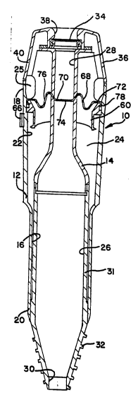
tl A generally tubular valve seat me_ber 60 is
; located in chamber 24 at the proximal end portion 18 of
outer trocar tube 12. The distal end of valve seat
member 60 is preferably angled, as best seen in FIG. 2.
A flap valve ~ember 62 of known construction is suitably
hinged at 64 and is movable betwe-n a ~-aling position
in ~oaling engagement with valve ~eat ~ ber 60, as
shown in phantom lines in FIG. 2, and an open position
removed Prom valve seat member 60, as shown in solid
lines in FIG. 2. Valve member 62 is biased into its
~, sealing position by a suitable spring means (not shown).
A lever member 66 located outside of chamber 24 is
} attached to hinge 64 to permit manual movement of valve
D' m~mher 62 between its sealing position against a sealing
lS gasket 67 attached to seat 60 into its open position -
against the spring bias. A sealing gas~et 68 is
- provided at the proximal end of valve seat m~ber 60 to
seal against the outer surface of trocar tube 14 or an
implement as it extends therethrough. Sealing gasket 68
, 20 is a bellows-type seal constructed in accordance with
-, the invention to facilitate maintaining a seal during
radial motion of instruments inserted therethrough.
Sealing gasket 68 includes a generally planar
inner section 70 and an outer section 72. An opening 74
¦ 2S is ~ormed through inner section 70 for allowing an
elongate instrument to pass therethrough in sealing ~
engagement therewith. A corrugated portion 76 i9 formed
,, in outer section 72 in surrounding relationship with
op ning 74 80 a~ to maintain the sealing engagement with
an elongato implem nt during of~-centering or radial
uotion Or the i~ploment with respect to the seal member.
The corrugated portion 76 extends above and below a
plane extending through the inner section 70. The outer
section 72 has a peripheral Plange portion 78 that is ~;
,.- . . ~.,.. j ., ,.. . . . ., . . , . , . ~ , : .
` . ' ' , '` ' . ` ': , - . .
.. . .. . . . ..
:. ~
r 2 1 2 ~ 8 ~ 7
` ~
~ 11 ~ ~
- .
suitably mounted in sealing engagement with outer trocar
tube 12 The corrugated portion 76 increases the
flexibility of the outer section 72 of seal member 68 to
enhance the sealing engagement of the seal member
Referring to FIGS 4-9, there is shown an
alternative trocar as~embly device 100 incorporating a
seal memb-r 134 constructed in accordance with the
invention The particular con6truction of the trocar
assembly device 100 does not for~ a part of the
lnvention
Trocar assembly device 100 includes a trocar
tube 112, an obturator 114, and a housing or handle 116
Trocar tube 112 defines an interior lumen having an open
distal end portion 118 and an open proximal end portion
120 Proximal end portion 120 extends into and is
mounted in a distal end portion 122 of handle 116 --
Handle 116 has an open proximal end portion 124 that
defines an opening 126 Opening 126 is provided with a
seal member assembly 128 that includes a seal member 134
constructed in accordance with the present invention and
described in detail herein-below
Obturator 114 is slidably and removably
extendable within trocar tube 112 and is inserted into
handle 116 and trocar tube 112 through seal member
2S as-embly 128 and opening 126 An obturator handle 132
is provided at the proximal end of the obturator and a
sharpened point or blade ~not shown) i8 ~ormed at the
dist~l ond thereor A~ is wall known in th- art, seal
momber a~-mbly 128 cooperate- with obturator 114, or a
~urgical instrumont extending through trocar tube 112,
to ~e~lingly ongage the outer surfac thereo~ and
thereby praclude the passage ef ~luids through handle
116. :~:
.. .. ........ ~ . ,, . . , .. -
.. . ., .. - .~ . ,
. . ~. ~,
.
:. ... ~,
,.~ . ... . .. .
; ' . - .. ,. ;..... . , : ~ ~
~ . . .
. -- 2120857
,
- 12 -
A flap valve ascembly 136 is suitably
supported in end portion 124. Flap valve assembly 136
defines a passageway 138 having a hinged flap valve 140
at the distal end thereof and an ela-tomeric seal member
134 at the proximal end thereof. A rigid or flexible
guide/retalner 142 is preforably secured within end
portion 124 to guide an obturator or imple~ont through
seal momber 134 into passageway 138 and to retain the
seal member.
Referring to FIGS. 5-9, the elastomeric seal
member 134, constructed in accordance with the
invention, includes a generally planar inner section 144 ~ `
and an outer section 146. An opening 148 is formed
through inner section 144 and is dimensioned to permit
an obturator or implement to pass therethrough in
sealing engagement therewith. A corrugated portion 150
is formed in outer section 146 in surrounding
relationship with opening 148. Corrugated portion 150
extends proximally from a plane passing through inner
section 144. The inner section 144 may be formed with a
greater thickness than corrugated portion 150. outer
section 146 is formed with a distally extending
peripheral wall or flange portion 152 having an inwardly
facing annular qroove or recess 154 formed therein.
Flange portion 152 is generally in axial alignment with
corrugated portion 150. A tongue portion 156 associated
with the flap valve assembly 136 is received in sealed
relation~hip with groove 154.
In accordance with an alternativ embodiment
of the invention, a plurality of spaced apart
pro~-ctions or ribs 158 may be provided to extend
outwardly from the proximally facing surface of the seal
member and radially with respect to opening 148.
Pro~ections 158 may be integrally formed in inner
-~ .
~, . .
~, . ~ . .
: ~
~,
- 13 -
. . .
, section 144 and a portion of corrugated portion 150 In
accordance with another embodiment of the invention, a
plurality of similar radially extending ribs 160 extend
outwardly from the distally facing surface of the seal
member and radially with re~pect to the opening 148
-, Ribs 160 are preferably not in axial aliqnment with ribs
3'i 158 and only extend from the inner section 144
r Referring to FIG 9, the ribs 158 and 160 have inner end
portions that are spaced a short distance from openinq
148 and beveled outwardly and away fro~ the inner
portion 144 of seal member 134 to guide an instrument
through opening 148 The ribs 158 and 160 are oriented
to form about a 45 degree angle with an ;~mediately
adjacent rib
In operation, as an elong~te obturator or
j instrument is directed through opening 148 in seal
member 134 in an off-centered relationship thereto, the
corrugated portion 150 enhances the flexibility of the
outer section 146 of seal member 134 to maintain sealing
engaqement between the inner section 144 of the seal
member and the implement
The projections or ribs 158 serve to reduce
surface contact betweon the outer surface of the seal
member and the instrument and thereby facilitate the
insertion of tho in~trument through opening 148 into
hou-ing 116 The pro~ections or ribs 160 ~erve to
reduce surface contact between the inner surface of the
¦ e~l m-mber and th- in~trument and th-reby facilitate
the removal of th- in-trument from the housing 116
through op-ning 148
Referring to FIGS 10-13, th-re i~ shown
another embodiment of a seal me~ber 234 constructed in
accordance with the present invention Seal member 234
is shown positioned in an exemplary trocar assembly 200
' ' , ` `
21208~7
- 14 -
having a housing 216 Houcing 216 has a proximal end
portion 224 that is provided with a flap valve assembly
; 236, a portion of which i8 shown in FIG 10
Seal member 234 includes a circular inner
section 244 and a generally oval outer section 246 An
opening 248 is formed through inner section 244 to
permit an obturator or implement to pass th-rethrough in
-aling engagem-nt th-rewith A corrugat-d portion 2~0
is ~ormed in outer section 246 in surrounding
relationship with opening 248 Corrugated portion 250
extends proximally of a plane passing through inner
section 244 Outer section 246 is formed with a
proximally extending peripheral wall or lip 252 that is
generally perpendicular to inner section 246 The outer
edge of wall 252 is formed as a bead portion 254 that is
received in sealing engagement between a guide/retainer ~--
242 and the inner surface of end portion 224
The seal m~er 234 may be pro~ided with
radially extending ribs or projections (not shown)
similar to ribs 158 or 160 discussed above with respect
to seal member 134 The operation of seal member 234 is - ~ -~
similar to that discussed above with respect to seal
member 134
Referring to FIGS 14-17, there is shown
anothor embodiment of a soal member 334 constructed in
accordance with the present invention Seal member 334
is similar in construction to seal m~mber 234 with the
addition of an annular floating ring tbat separates and
i~olat-- tbe inner s-ction from tbe outer section to
~acilitat- movement o~ tbe outer section while
maintaining tbe inner section in sealing engagement witb
an instrument Seal member 334 is shown positioned in
an exemplary trocar assembly 300 bavinq a housing 316
Hou~ing 316 has a proximal end portion 324 tbat is
- . . ~.
. . . ~ . .. ~, .
. .. ...:.
,
.
.. ;
. ,
` - 21208~7
.; .
s - 15 -
. .
provided with a flap valve assembly 336, a portion of
which is shown in FIG 14
Seal momber 334 includes a circular inner
section 344 and a generally oval outer section 346 An
opening 348 is rormed through inn-r section 344 to
~' permit an obturator or instrument t,o pass therethrough
t, in s-allng engagement therewith A corrugated portion
3SO is ~orm-d in outer soction 346 in surrounding
i relationship with opening 348 Corrugated portion 350
extenda proximally from a plane passing through inner
aection 344 Outer section 346 is formed with a
; proximally extending peripheral wall or lip 352 that is
gonerally perpendicular to inner section 346 The
i proximal edge of wall 352 is formed as a bead position
354 that is received in sealing engagement between a
` guide/retainer 342 and the inner surface of end portion
324
The inner section 344 may be provided with
radially extending ribs or projections (not shown)
similar to ribs 158 or 160 discussed above with respect
i to seal member 134
An annular floating ring portion 362 separates
inner section 344 from outer section 346 Floating ring
portion 362 extends outwardly from either the proximally
and/or the distally facing surfacea of seal member 334
! Floating ring portion 362 i~ preferably molded
integrally witb the seal memb-r ao as to rorm a semi-
rigid ring or collar Alternativ-ly, rloating ring
portlon 362 may be formed Or a rigid or ae~i-rigid
material, such as plaatic, metal or the like, that is
either molded into the seal memb-r or suitably attached
thereto
The operation of seal member 334 is similar to
that di~cussed above with respect to seal member 134
. ' ~:.` . . . '. , .
` `- ` , '''` , ~ ' ` :' `
~-: ..:
..
,,
~,
.- ` 2120857
.~ :
~he floating ring portion 362 allows the inner section
344 to seal against an instrument and the outer section
346 to be compliant and move laterally with off-center
lor sideways) forces on the instrument In so doing,
the lnner ~ection 344 is isolated and tha sideways
~ovement o~ the instrument does not disrupt the seal,
but infitead deflects the outer section 346 that is
external to the ring portion 362
Re~erring to FIGS 18-20, there is shown yet
another embodlment of a seal member 434 constructed in
accordance with the present invention wherein the --
corrugated portion 450 includes at least two
corrugations formed therein Seal member 434 is shown
positioned in an exemplary trocar ass~mbly 400 having a
housing 416 Housing 416 has a proximal end portion 424
that is provided with a flap valve ass~hly 436 ~ -
Seal member 434 includes a circular inner ~`
section 444 and a generally circular outer section 446
An opening 448 is formed through inner section 446 to
permit an obturator or implement to pas~ therethrough in
sealing engagement therewith A corrugated portion 450
is formed in outer section 446 in surrounding
relationship with opening 448 Corrugated portion 450
includes an inner corrugation 464 and an outer
corrugation 466 Inner corrugation 464 extends distally
o~ the plane that passes through inner ~ection 444 and
outer corrugation 466 extends proximally of such plane
Outer section 446 is formed with a proximally extending
annular flange portion 452 having a groova or recess 454
formed therein Flange portion 452 i8 received in an
annular recess 468 formed in flap valv~ bly 436 A
rigid or flexible guid-/retainer member 442 is provided
to guide an obturator or implement through seal me~ber
434 into passageway 438 Guide/retainer member 442
~r,~.. . . : . ' ' '' '
, ~ .
- .
. ~ -
21208~7
- 17 -
includes a distally extending flange portion 470 that is
received in recess 454 to retain seal me~ber 434 in
sealing engagement with flap valve asse~bly 436
A plurality of spaced apart projections or 5 ribs 458 m~y be provided to extand outwardly from the
proximally ~acing surrace of the seal me~ber and
radially with respect to opening 448 Proj-ctions 458
are integrally form d in innor section 144 A plurality
of similar radially extending ribs 460 may be provided
to extend outwardly from the distally facing surface of
the seal member Rib6 460 may, or may not, be in axial
alignment with ribs 458 The inner and outer ~nd
portions of rib6 458 and 460 are beveled as shown in
FIG 20 -~
The operation of seal m~ber 434 i8 similar to
that discussed above with respect to seal ~her 134
Referring to FIGS 21-22, there is shown a
further embodiment of a seal member 534 constructed in
accordance with the invention Seal m~b~r 534 is
similar in construction to seal member 434 and includes
a floating annular ring portion 562 that separate= the
inner section 544 and the outer section 546 The common
elements of seal members 434 and 534 are identified by
reference numorals having the same last two digits and
reference is made to th- above di-cussion of such
elements
Float~ng ring portion 562 i~ shown extending
proximally ~rom tho outer surface of ~eal member 534 and
i- molded integrally th-rewith However, the floating
ring portion 362 may be alternatively formed as
discu-~ed above with respect to seal member 334 ~s
shown in FIG 22, the outer portion Or inner section 544
may be formed to have an increased thickness
. . ... :.. .... ... ~
.: ~ -
., ; ~ . . .;. .. ; ~ .. ~ ..
` . . . :- - , . . :
. . . . -
. ~:: , ` :
.: : :~ .: . '
:
` -- 21208~7
;`. `
" .. . . .
.
: Referrinq to FIGS. 23-24, there is shown a
still further embodiment of a seal member 634
constructed in accordance with the invention. Seal
member 634 i8 Bimilar in construction to 8e~1 member 434
except that the corrugated portion includQs a single
corrug~tion. The common lements o~ seal ~embers 434
;; and 634 are identified by reference numerals having the
same last two digits and reference i8 ~ade to the above
discussion of such elements.
Referring to FIGS. 25-28, there i8 shown yet
~r another embodiment of a seal member 734 constructed in
accordance with the invention. Seal member 734 is
similar in construction to seal member 634 except that
; the inner section does not include the proxi~lly or
distally facing radial ribs and is provided with
radially extending pleats formed therein. The common
~; elements of seal m~ers 634 and 734 are identified by
, reference numerals having the ~ame la~t two digits and
J reference is made to the above discussion of such
'l 20 elements. .
¦ Inner section 744 is formed with pleats 770 ~ `
~ that extend radially from a center hub portion 772 that -~
i surrounds opening 748 and a floating ring portion 762 ~ `
; that separates inner section 744 from outer section 746.
In accordance with a preferred embodiment the pleats 770
have an included angle of about 52 degrees. The pleats
have a height that is subatantially equal to tho
thickness of the center hub portion 772 and the floating
ring portion 762.
The 8eal ~e~b-rs disclosed herein aro
preferably made ~rom an elastomeric material sucb as
silicon, latex, rubber, polyurothane, Xraton- (a
thermoplastic elastomeric A-B-A, styrene-i~oprene-
`.:
.'.,
8 ~ ~
`;
. -- 19 --
.,
styrene, block copolymer manufactured by Shell Chemical
Company) or the like.
.'~ From the foregoing it will be observed that ~ :
~; numerous modifications and corrections can be effected
without departing from the true spirit and scope of the
; novel concepts of the present invention. It will be
understood that no limitation with respect to the
,~ ~pecific embodiments illu~trated herein i~ intended or
should be inferred. It is, of course, intended to cover
by the appended claims all such modifications as fall
vlthln the cope of the claim~.
.,:' . `~ ' ` , ~