Note: Descriptions are shown in the official language in which they were submitted.
~ 212~.9~0
Multi-Pur~ose Wine Bottle Sto~per Device
Backqround of the Invention
This invention relates to a device for removing a stopper
from a bottle, and more particularly, for removing either a
cork or a mushroom-shaped stopper from a wine bottle.
It is now commonplace to use a form of plastic stopper
for wine bottles, particularly sparkling wine or champagne
bottles. These plastic stoppers have the advantage of being
very inexpensive, but they do present problems that are
avoided with traditional bottle corks. Thus, when removing
traditional corks, a cork screw is turned into the cork for
pulling and this not only provides a pulling means but also a
means for controlling the cork from flying when released from
the bottle. It is not possible to use a cork screw with a
plastic stopper and, therefore, these stoppers are formed with
a bulbous head as a means for grasping the stopper for
pulling. Because this is not a very efficient means for
pulling, it is commonplace to form the stopper with a
relatively loose fit in the bottle and provide a wire cage
over the bulbous head to hold the stopper from accidentally
releasing due to pressure in the bottle. This pressure may be
as high as 40 psi. Also, when the plastic stopper is released
it frequently becomes a dangerous projectile with the release
of gas pressure in the bottle and has caused serious eye
injuries. Because the plastic stopper is a dangerous
projectile, some wine makers for safety reasons actually use
much more expensive mushroom-shaped stoppers formed from cork.
A cork stopper inflicts much less damage as a projectile than
does a plastic stopper.
There is still a need for a very simple and inexpensive
device which is very easy to use and which is capable of
removing a plastic bottle stopper without allowing the stopper
to become a projectile. To be commercially viable, the device
must also be very easy to use, while being formed from a bare
minimum of plastic parts.
Numerous devices have heretofore been proposed for
removing stoppers from bottles. A particularly significant
' ` ' , : ~, . .
~ 2120960
design is that shown in U.S. Patent 4,756,214 which issued
July 12, 1988. The device of this patent goes a long way to
meeting the above criteria ln terms of safety but it remains a
relatively complicated device including a slidable collar to
permit engagement with the mouth of the bottle.
An example of the use of a wire cage to prevent
accidental release of a stopper is shown in U.S. Patent
4,708,033. Because a stopper will sometimes pop out by itself
when the wire cage is removed, it is important that the
stopper pulling device be designed such that the wire cage can
be loosened after the pulling device has been placed on the
bottle.
Of course, the traditional cork is also widely used for
wine bottles and it would be most convenient if there could be
a single stopper removing device which would be capable of
removing either a traditional wine bottle cork or the
mushroom-shaped plastic stoppers.
It is a primary object of this invention to provide a
stopper pulling device which is capable of pulling either a
traditional cork or a mushroom-shaped plastic stopper from a
bottle.
It is a further object of the present invention to
provide a dual purpose stopper pulling device particularly for --
wine bottles which will not only be convenient and safe to
use, but also be simple and very inexpensive to manufacture
thereby making it readily accessible to all wine consumers.
Summar~y of the Invention
The present invention relates to a device for removing
either a cork or a mushroom-style stopper from a bottle. It
includes: (a) a support frame having a bottom ring member
adapted to engage the neck of a wine bottle, a top cap member
with a threaded hole extending therethrough and at least two
circumferentially spaced longitudinal support members
extending between the top cap and bottom ring, (b) a threaded
shaft having an upper end and a lower end mounted in said top
cap threaded hole, this shaft having a handle mounted on the
upper end thereof, (c) a stopper gripping and pulling member
-' 2120960
for a mushroom-shaped stopper comprising a bridge member
connected to the lower end of said threaded shaft such that
the threaded shaft is free to rotate relative to the bridge
member while being fixed against relative axial movement,
guideways in said bridge member for receiving said support
frame longitudinal support members thereby preventing rotation
of said bridge member, a pair of opposed stopper gripping arms
extending downwardly from said bridge member, said gripping
arms having at the lower ends thereof inwardly extending
gripper dogs adapted to slide downwardly over the top of a
mushroom-shaped stopper in a bottle and grip the stopper for
pulling and these gripper arms being further adapted to swing
outwardly from said bridge member to release a pulled stopper,
and (d) a cork pulling member comprising a stem portion with a
handle at one end and cork screw portion at the other end,
said cork screw stem extending through an axial hole in said
threaded shaft with the cork screw handle projecting above
said threaded shaft handle, said cork screw member being
adapted to be screwed into a cork in a bottle by turning the
cork screw handle and being adapted to pull the cork from the
bottle by turning the handle of the threaded shaft whereby the
thread shaft handle engages the cork screw handle thereby
lifting the cork screw and cork.
According to a preferred feature, a disc member is
attached to the lower end of the threaded shaft and this disc
member has an axially upwardly extending collar which is
received in a hole in the bridge member, thereby permitting
rotation of the shaft relative to the bridge member.
Preferably, the disc member is permanently fixed to the lower
end of the threaded shaft, while the handle is removably
attached to the top end. In this way, the threaded shaft can
be passed through the hole in the bridge member before the
handle is connected and resilient tabs can be provided
projecting from the threaded shaft to prevent axial movement
of the bridge along the shaft.
The cork pulling member extends downwardly through holes
in the threaded shaft, the handle thereof and the bottom disc.
- . . . .
A ~12 ~9 fi(~
Preferably, the cork pulling member includes at the upper end
of the stem a shoulder portion adapted to press against the
threaded shaft handle duri.ng the cork pulling operation.
The bridge member is preferably provided with lines of
weakness forming self-hinges permitting the gripper arms to
swing outwardly and release a pulled stopper.
It will also be appreciated that the device may be
produced without the cork pulling member and thus sold only as
a device for pulling mushroom-shaped stoppers.
All parts of the device of this invention can be
conveniently made from a variety of injection mouldable
plastic materials, but a strong plastic such as DERLIN~ is
preferred.
Brief Descri~tion of the Drawinqs
In the drawings which illustrate the present invention:
Figs. 1, 2, 2a and 3 are side elevational views of
embodiments of the devlce of the invention;
Fig. 4 is a plan view of a gripping unit;
Fig. 5 is a side elevational view of a gripping unit;
Fig. 6 is a bottom plan view of the handle for the
threaded shaft;
Fig. 7 is a top plan view of a frame portion;
Fig. 8 is one side elevation of the frame portion; -
Fig. 9 is a second side elevation of the frame portion;
Fig. 10 is a bottom plan view of a threaded shaft
assembly;
Fig. 11 is a side elevational view of the threaded shaft
assembly;
Fig. 12 is a top plan view of the threaded shaft
assembly;
Fig. 13 is a top plan view of a corkscrew; and
Fig. 14 is a side elevational view of the corkscrew.
Descri~tion of Preferred Embodiments
Typical examples of the stoppers that can be removed with
the device of this invention are shown in Figs. 1-3. Thus,
the stopper 60 shown in Figs. 1, 2 and 3 is a traditional
cylindrical natur~l cork stopper that can be removed from a
.~.............. , ~ , ' , . .
2120~60
bottle only by means of a corkscrew which is turned into the
cork. Flg. 2a shows a typical mushroom-shapecl stopper of the
type typically found in champagne and sparkling wine bottles.
These stoppers are typically made of plastic materials with a
bulbous top portion 30, a cylindrical stopper portion 31 and a
shoulder 32 formed between the top portion 30 and the stopper
31. Of course, these plastic stoppers cannot be removed by a
traditional corkscrew. The apparatus of the present invention
pulls both of the above types of bottle stoppers with ease.
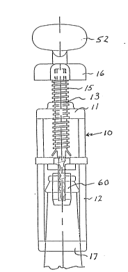
There are four main components to the device of the
invention, these being (1) a support frame, (2) a threaded
shaft with handle, (3) a stopper grippiny and pulling member
and (4) a cork screw and puller. The support frame 10
includes a bottom ring member 17 adapted to slide down onto
and engage a wine bottle neck 40. The frame also includes a
top cap member 11 with a threaded hole 13 extending
therethrough. The ring 17 and cap 11 are joined by means of
at least two longitudinal support members or rods 12. The
structure of this support frame can best be seen from Figures
7, 8 and 9.
A threaded hollow shaft 15 extends downwardly through the
threaded hole 13 in top cap 11. A handle 16 is affixed to the
top end of shaft 15 while the lower end of the shaft is rota- -
tably connected to the stopper gripping and pulling member 20.
The stopper gripping and pulling member 20 (referred to
hereinafter as the gripper) includes a top or bridge member 21
with gripper arms 22 extending downwardly therefrom. The
gripper arms 22 have inwardly extending gripping dogs 23 and
the bottom ends of the gripping arms have concave faces 24.
The top or bridge portion 21 has a central hole 26 for
mounting to the bottom end of threaded shaft 15. This
mounting is achieved by means of a mounting disc 41 as shown
in Figures 10-12. This disc 41 inGludes an upwardly extending
annular shoulder portion 42 which Eits into hole 26 in bridge
portion 21 of gripper 20 and serves as a pivot. The disc 41
and shoulder portion 42 are preferably permanently connected
to the threaded shaft 15 and this assembly is joined to the
:
,~ 212~960
gripper 20 by passing the upper end of the threaded shaft
through hole 26 before handle 16 .is connected to the top end
of threaded shaft lS. The handle 16 preferably includes an
annular shoulder 46 with an axlal hole 47 which fits over the
top end 45 of the threaded shaft 15. As the threaded shaft 15
is passed through the hole 26, projecting resilient tabs or
stops 44 formed on shaft 15 pass through the hole 26. In this
manner, the threaded shaft is free to turn relative to the
gripper 20 by means of the collar 18, while the stops 44
prevent axial movement between the shaft 15 and gripper 20.
The gripper 20 also includes in the bridge portion 21
guideways 27 which receive the rods 12 of the frame assembly.
Thus, the gripper slides upwardly and downwardly within the
frame assembly and is prevented by rotation by engagement
between the guideways 27 and the rods 12.
The bridge portion 21 of the gripper 20 is also
preferably provided with grooves or lines of weakness 25 which
form self hinges of the portions attached to the gripper arms
22, the purpose of which will be explained hereinafter.
The cork screw portion for removing traditional corks is
shown by the numeral 50 and it has a cylindrical stem portion ~ ;~
51 with a handle 52 at the top end and a cork screw thread 53
at the bottom end. It also preferably includes a shoulder
member 54 directly below the handle 52 for engaging the top
face of threaded shaft handle 16. The stem 51 of cork screw
50 extends through axial holes in the handle 16, threaded
shaft 15, bridge portion 21, mounting disc 41 and shoulder
portion 42.
The manner in which the device of this invention may be
used for removing a mushroom-shaped plastic stopper is shown
in Figure 2a. Thus, the handle 16 is rotated to move the
gripper 20 to an upper position within the frame 10 and the
frame ls then placed over the end of a wine bottle and allowed
to slide downwardly on the neck until the bottom ring 10 of
the frame firmly engages the neck 40. The handle 16 is then
turned causing the gripper 20 to move downwardly until the
gripper teeth 23 have snapped below the shoulder portion 32 of
.. , .. ~ . ...
. . ;~ -: -
': ' .. .' : . ;.
~: :
,.
. . .
:' :
2 1 C~ 6 0
the stopper 30.
The handle 16 is then rotated causing the yripper 20 to
move upwardly and pulling ~he stopper 30 from the bottle. The
stopper eventually releases from the bottle with a pop, but is
prevented from flying because it is firmly held within the
gripper arms 22 and the rods 12. Thus, it can ~ove upwardly
only the short distance until it abuts against the disc member
41.
The used stopper 30 is easily removed from the gripper
simply by placing one's thumbs in the concave faces 24 of
gripper arms 22 and spreading the arms apart so that the
stopper falls out.
The use of the device of the invention for removing
traditional corks from wine bottles is shown in Figures 1, 2
and 3. It can be seen that the cork screw portion 50 simply
slides up and down within the hollow threaded shaft 15 so that
when the device is being used to remove a mushroom-shaped
plastic stopper as described above, the cork screw portion 50
is slid up out of the way of the action of the gripper 20 as
illustrated in Figure 2a. When the device is to be used to
remove a cork 60 from a bottle 40, the frame is placed over
the end of a wine bottle 40 and allowed to slide downwardly on
the neck until the bottom ring 10 of the frame firmly engages
the neck. The handle 16 is turned to move the disc 41 down
25 close to the top of cork 60 and at this point the cork screw ~-
handle 52 is turned causing the threaded portion 53 to screw
into the cork 60 as shown in Figure 1. Now the handle 16 is
turned causing the threaded shaft 15 to rotate with respect to
the frame and forcing the handle 16 to thereby move in an
upward direction relative to the bottle 40. This applies an
axial upward force on the shoulder 54 of the cork screw 50
thereby pulling the cork 60 in an upward direction as shown in
Figure 2. When the cork 60 has released from the bottle, the
device can be removed from the bottle as shown in Figure 3.
At this point, the cork screw handle 52 can be turned in a
reverse direction to remove the threaded portion 53 from the
. cork 60.
.:
~'
::
21~09~0
The stopper pulling device of this invention has several
important advantages over the prior art. Most importantly, it
is extremely easy to use with the result that it will be used
and not be relegated to being another useless gadget.
Secondly, it is very simple and easy to manufacture, with the
result that it can be sold at a price which can easily be
afforded by anyone who can afford a bottle of wine. Finally,
it is the only stopper removing device that is needed because
it is equally useful for removing either traditional bottle
corks or the mushroom-shaped plastic stoppers.
The present invention may be embodied in other specific
forms without departing from its spirit or essential
attributes. Accordingly, reference should be made to the
following claims rather than the foregoing specification, as
indicating the scope of the invention.