Language selection

Search

Patent 2120977 Summary

Third-party information liability

Some of the information on this Web page has been provided by external sources. The Government of Canada is not responsible for the accuracy, reliability or currency of the information supplied by external sources. Users wishing to rely upon this information should consult directly with the source of the information. Content provided by external sources is not subject to official languages, privacy and accessibility requirements.

Claims and Abstract availability

Any discrepancies in the text and image of the Claims and Abstract are due to differing posting times. Text of the Claims and Abstract are posted:

  • At the time the application is open to public inspection;
  • At the time of issue of the patent (grant).
(12) Patent Application: (11) CA 2120977
(54) English Title: IMPELLER WITH ALTERNATING PRIMARY AND SECONDARY VANES OF DIFFERENT GEOMETRIES
(54) French Title: TURBINE AVEC AUBAGES PRIMAIRE ET SECONDAIRE DE GEOMETRIES DIFFERENTES
Status: Dead
Bibliographic Data
Abstracts

English Abstract


The present invention relates to the design of impellers for
radial, centrifugal or mixed flow liquid and gas pumps and
turbines. The impeller features a number of primary and
secondary vanes (or blades). The primary vanes extend from the
eye of the impeller to the tip diameter or periphery of the
impeller. The secondary vanes extend from a higher radius
outside the eye of the impeller to the tip diameter or
periphery of the impeller. The primary and secondary vanes
alternate. The role of the secondary vanes is to control the
expansion and the slip between the primary vanes particularly
towards the periphery of the impeller.


Claims

Note: Claims are shown in the official language in which they were submitted.


CLAIMS
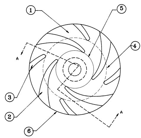
1- An impeller (1) for liquid , gas ,slurries and solid
handling pumps as represented in Fig(1) featuring a number of
primary vanes (2) and secondary vanes (3), wherein the primary
vanes extend from the eye of the impeller (5) to the tip
diameter or periphery of the impeller (6), while the secondary
vanes extend from a radius (4) outside the eye of the impeller
to the tip diameter or periphery of the impeller; or are of a
different geometry, curvature or chord than the primary vanes
and whereas the primary and secondary vanes alternate, with
the secondary vanes playing a role of dividing the flow
between the primary vanes to control the expansion and the
slip between the primary vanes particularly towards the
periphery of the impeller.
2- The principle of the impeller can be applied to the
closed,semi-closed, open,semi-open, reverse vane impellers
with single or double suction, for radial, mixed or
centrifugal pumps and turbines.


Description

Note: Descriptions are shown in the official language in which they were submitted.


2.0 DESCRIPTION OF THE CONCEPT 2 / 2 ~ ~ 7 7
Slip is a recognized phenomenon in impellers of turbomachines.
A slip factor is usualLy defined as the ratio as
y = Ct,t. / C~t
where C~t, is the actual peripheral velocity at the tip
diameter of the impeller
Cut is the design peripheral velocity (obtained from the tip
speed and the relative velocity due to the vane tip angle~
The classical theory of slip was initially developed by
Stodala who established a relationship between the slip factor
Y and the number of vanes as
Y = 1 - PI * sin ~tltZ
4~
where PI=3.1415
Bt = vane tip angle
Z = Number of vanes
Stodala's theory has been refined in the last few decades by
various pump designers to take in account the vane profile,
the relationship between casing and impeller. However ~ost
theories concord that s~ip is minimized by increasing the
number of the vanes up to a certain limit where flow could be
5~ blocked by an excessive number of vanes. Thus typically many
water pumps have 6 to 8 vanes for their impellers.

~o~ss~
~C ~S~z 2 1 2 0 9 7 7
_ B E.ABULNAGA ~

In the case of slurry pumps there are certain criteria of
~CE oF o acceptable particle size passage way and non clogging that
restricts the number of vanes. Thus many small slurry pumps
with a diameter of less than 14t' (350 mm) may have 2,3, or 4
S vanes. This tends to increase slip and decrease efficiency.
The inventor in an effort to design efficient impellers for
for slurries examined the flow through an ~mpeller. In the
case of a conventional impeller the distance between the vanes
1~ is found to be smaller at the eye of the impeller (2*PI*R -
Z~t3~Z ~where t is the local thickness of the vane3 than at
the periphery. As the flow moves through the impeller it
experiences an expansion due to the increased spacing between
vanes. If such an expansion is too acute some breakdown of the
flow may occur causlng eddies and even reversal of the flow.
Thus every pump has a reg~on of best efficiency in which it is
recommended for use.
In an effort to reach a compromise between sufficient number
of vanes to minimlze slip without obstructing flow at the eye
as to reduce particle size passage ways, the inventor decided
to maintain a limited number of vanes as in conventionaL
impellers that the inventor called primary or principal vanes
but to introduce a second set of secondary vanes between the
primary vanes outside the eye of the impeller to extend to the
tip diameter or periphery of the impeller. The primary and
secondary vanes alternate. The role of the secondary vanes is
to control the expansion and the slip between the primary
vanes partlcularly towards the periphery of the impeller.
Thus referring to fig (13 which shows an embodiment of the
invention. Starting at the eye (53 one notices a number of
vanes ~2~ which extend from the eye of the lmpeller to the
periphery of the impeller. These vanes are the type of vanes
found in conventlonal pump impellers. They are equldistant and
of identical geometry. they are referred to, in the present
invention as primary vanes. As notlced ln fig ~13 the distance
between the primary vanes increases with the radlus allowlng
expansion of the flow.
At a certain dlameter ~4~ a set of secondary vanes ~33 are
introduced. Their role ls to divlde the flow between the
primary vanes. They reduce the expanslon angle and create
additlonal channels. It is a fundamental princlple of fluid
4~ dynamics that if the expanslon angle is too large ~ larger
than 15 degrees) that some pressure losses and additional flow
reversal may occur. Thus the secondary vanes help to prevent
an acute expansion angle particularly in solid handllng pumps
by splltting lt lnto two smaller expansion angles (fig 2~.
The selection of the starting radlus for the secondary
vanes is a matter of design. They could ~e started close to

2120977


the eye or well far from it. The principle is to avoid
blocking the flow at the eye. In solid handling pumps it is
advised to start the secondary vanes at a radius to al~ow
sufficient particle passage way.


The principle of the impeller with alternating vanes of
different geometries may be applied to open, semi-open, semi-
closed , closed ,single suction, double suction - Fig (21
shows an cross-sectional representation of an open, double
suctlon impeller. Such an impeller was manufactured - Photos
are included in the annex attached hereunder. In this
particular design the primary vanes on the front shroud are
out of phase with the vanes of the back shroud but they can be
equally in phase back to back.
Fig (3) shows another embodiment of the invention by applying
the principle to closed impel1er with shrouds on both sides of
the vanes.

Representative Drawing
A single figure which represents the drawing illustrating the invention.
Administrative Status

For a clearer understanding of the status of the application/patent presented on this page, the site Disclaimer , as well as the definitions for Patent , Administrative Status , Maintenance Fee  and Payment History  should be consulted.

Administrative Status

Title Date
Forecasted Issue Date Unavailable
(22) Filed 1994-04-11
(41) Open to Public Inspection 1995-10-12
Dead Application 2001-04-11

Abandonment History

Abandonment Date Reason Reinstatement Date
1998-04-14 FAILURE TO PAY APPLICATION MAINTENANCE FEE 1998-04-20
2000-04-11 FAILURE TO PAY APPLICATION MAINTENANCE FEE

Payment History

Fee Type Anniversary Year Due Date Amount Paid Paid Date
Application Fee $0.00 1994-04-11
Maintenance Fee - Application - New Act 2 1996-04-11 $50.00 1996-03-05
Maintenance Fee - Application - New Act 3 1997-04-11 $50.00 1997-03-13
Reinstatement: Failure to Pay Application Maintenance Fees $200.00 1998-04-20
Maintenance Fee - Application - New Act 4 1998-04-14 $50.00 1998-04-20
Maintenance Fee - Application - New Act 5 1999-04-12 $75.00 1999-02-22
Owners on Record

Note: Records showing the ownership history in alphabetical order.

Current Owners on Record
ABULNAGA, BAHA ELSAYED
Past Owners on Record
None
Past Owners that do not appear in the "Owners on Record" listing will appear in other documentation within the application.
Documents

To view selected files, please enter reCAPTCHA code :


To view images, click a link in the Document Description column. To download the documents, select one or more checkboxes in the first column and then click the "Download Selected in PDF format (Zip Archive)" or the "Download Selected as Single PDF" button.

List of published and non-published patent-specific documents on the CPD .

If you have any difficulty accessing content, you can call the Client Service Centre at 1-866-997-1936 or send them an e-mail at CIPO Client Service Centre.


Document
Description 
Date
(yyyy-mm-dd) 
Number of pages   Size of Image (KB) 
Cover Page 1995-11-23 1 15
Abstract 1995-10-12 1 25
Claims 1995-10-12 1 36
Description 1995-10-12 3 133
Drawings 1995-10-12 3 146
Representative Drawing 1999-07-13 1 13
Correspondence 1998-06-15 2 65
Assignment 1994-04-11 5 233
Prosecution-Amendment 1998-04-20 3 157
Fees 1998-06-03 2 3
Fees 1999-02-22 2 92
Fees 1998-04-20 2 67
Fees 1996-03-05 1 22
Fees 1997-03-13 1 26